JP3663473B2 - Assembled transporter - Google Patents
Assembled transporter Download PDFInfo
- Publication number
- JP3663473B2 JP3663473B2 JP01197695A JP1197695A JP3663473B2 JP 3663473 B2 JP3663473 B2 JP 3663473B2 JP 01197695 A JP01197695 A JP 01197695A JP 1197695 A JP1197695 A JP 1197695A JP 3663473 B2 JP3663473 B2 JP 3663473B2
- Authority
- JP
- Japan
- Prior art keywords
- shelf
- pipe
- column
- support
- hook
- Prior art date
- Legal status (The legal status is an assumption and is not a legal conclusion. Google has not performed a legal analysis and makes no representation as to the accuracy of the status listed.)
- Expired - Lifetime
Links
Images

Landscapes
- Handcart (AREA)
Description
【0001】
【産業上の利用分野】
この発明は、組立式運搬車に関する。
【0002】
【従来の技術】
従来、組立式運搬車として、キャスタ付き基台に前後一対の支柱支持用パイプが左右に複数対並んで固定された台車と、前後一対の支柱支持用パイプに差し込まれる前後一対の中空状支柱および前後支柱間に渡し止められた複数の横桟を備えた棚形成用部材と、前後両端に各支柱の上端中空部に差し込まれる前後複数対の支柱補強用パイプが固定された補強用枠部材とよりなるものが知られている(実開昭64−45573号公報参照)。
【0003】
【発明が解決しようとする課題】
上記従来の組立式運搬車では、組立および分解が可能であるという長所を有するが、台車より取り外した棚形成用部材および補強用枠部材がそれぞれかなりの格納スペースを必要とし、特に運搬車が複数台ある場合には、格納に必要な床面積を少なくすることはできなかった。
【0004】
この発明の目的は、組立が容易で、運搬車を使用しないときや運搬車だけを移動させるさいの格納スペースが少なくて済み、しかも複数の運搬車を格納するのに必要な床面積を少なくすることができる組立式運搬車を提供することにある。
【0005】
【課題を解決するための手段】
本発明による組立式運搬車は、平面より見て左右方向に長い略方形の基台を有する台車と、基台の四隅に設けられ且つ支柱受止め部を有する所要長さの支柱支持パイプと、下端部が支柱支持パイプに着脱自在に差し込まれ且つ上下方向に所定間隔おきにフック部掛止め用孔が設けられた支柱と、フック部掛止め用孔に引っ掛けられるフック部を四隅に有する複数の棚とを備え、台車を積み重ねた際に、上位の台車におけるパイプの下端部と下位の台車におけるパイプの上端部とが嵌め合わされ、支柱は、左右方向に対向する前後各1対のパイプの間隔と同一または僅かに短い長さとなされ且つ両端には突起が設けられており、前記左右方向に対向する前後各1対のパイプの対向壁には、その上端部から下方向へ伸び且つ2本の支柱の各端にある突起および全棚の各隅にあるフック部を上下方向に並べて挿入し得る長さのスリットが設けられているものである。
【0006】
また、本発明では、上記棚の前縁部の下部互いに当接し合う前後2つの弾性材からなる値札挟止用部材が設けられ、両部材間に値札が下方から差し込み可能となされているものである。
さらに、本発明では、各棚が、フック部および挟止用部材が設けられた棚受け枠と、棚受け枠に水平状態にも前方に傾斜した状態にも受けられる取り外し可能な棚板とからなるものである。
【0007】
【作用】
本発明の組立式運搬車によると、これを組み立てるさいには、各支柱支持パイプにそれぞれ支柱を差し込んだ後、支柱の所定高さのフック部掛止め用孔に棚のフック部を差し込んで、棚を支柱に取り付ける。
【0008】
運搬車を使用しないときや運搬車だけを移動させるさいには、台車から支柱および棚を取り外した後、各支柱支持パイプのスリットに棚の四隅のフック部をそれぞれ挿入すると共に対向するスリットにそれぞれ2本ずつ支柱の突起を挿入することにより、当該台車上に棚および支柱を積み重ねた状態で固定することができる。
【0009】
また、運搬車が複数台あるときには、棚および支柱が積まれた台車を積み重ねていくが、この際には、上に載せる台車の支柱支持パイプ下端部を下にある台車の支柱支持パイプ上端部に嵌め合わせることで、上位の台車と下位の台車との間に支柱支持パイプの高さ分だけのスペースが確保され、このスペースに棚および支柱が納められた状態となされる。
【0010】
更に、本発明では、上記棚の前縁部の下部に、互いに当接し合う2つの弾性材からなる値札挟止用部材を設け、両部材間に値札を差し込むだけで、棚に値札を付けることができる。
【0011】
【実施例】
本発明の実施例を、以下図面を参照して説明する。
【0012】
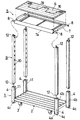
図1〜図7において、運搬車は、平面より見て左右方向に長い略方形の基台(2)を有する台車(1)と、基台(2)の四隅に設けられ且つ支柱受止め部(4a)を有する所要長さの有底状の支柱支持パイプ(4)と、下端部が支柱支持パイプ(4)に着脱自在に差し込まれ且つ上下方向に所定間隔おきにフック部掛止め用孔(10)が設けられた支柱(9)と、フック部掛止め用孔(10)に引っ掛けられるフック部(8)を四隅に有する複数の棚(5)とを備え、台車(1)を積み重ねた際に、上位の台車(1)におけるパイプ(4)の下端部と下位の台車(1)におけるパイプ(4)の上端部とが嵌め合わされ、支柱(9)は、左右方向に対向する前後各1対のパイプ(4)の間隔より僅かに短い長さとなされ且つ両端には突起(12)が軸支されており、前記左右方向に対向する前後各1対のパイプ(4)の対向壁には、その上端部から下方向へ伸び且つ2本の支柱(9)の各端にある突起(12)および全棚(5)の各隅にあるフック部(8)を上下方向に並べて挿入し得る長さのスリット(11)が設けられているものである。
【0013】
台車(1) は四隅近くにキャスタ(3) が取り付けられている。台車(1) の支柱支持パイプ(4) の外側壁には凹部(4b)が全長にわたって設けられ、該凹部(4b)の下端部には止め片(4c)が下方突出状態に軸着されている。
【0014】
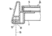
棚(5) は、長方形の棚板(6) と、これを受ける棚受け枠(7) とよりなる。棚受け枠(7) を構成する枠部材のうち、前側枠部材(7a)の下部には、図7に示すように、互いに当接し合う2つのゴム製の値札挟止用部材(13)が設けられ、両部材間に値札(15)を差し込むことにより、該値札(15)が垂下状態に挟み止められる。
【0015】
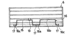
図1、図5および図6に示すように、棚板(6) の後縁寄り位置には、2つの凸形部(16b) と両凸形部(16b) 間の凹形部(16a) および両端部(16c) からなる1本の屈曲した支持棒(16)が設けられている。この支持棒(16)は、その凹形部(16a) および両端部(16c) がそれぞれ止部(17)により棚板(6) の下面に揺動自在に取付けられ、両凸形部(16b) が棚受け枠(7) の後縁部下面に一体的に設けられた保持具(18)のV形溝部(18a) 内に嵌め入れられるか又は一方の凸形部(16b) が棚板(6) の下面に設けられた対応する掛止部(19)に掛け止められるようになされている。
【0016】
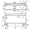
支持棒(16)の両凸形部(16b) を棚受け枠(7) における保持具(18)のV形溝部(18a) 内に嵌め入れた場合には、図2および図6に示すように、棚板(6) が前方へ傾斜した状態となされる。また、この棚板(6) が傾斜した状態において、前側の2本の支柱(9) 間には、必要に応じて、陳列品の保持用ベルト(21)が渡し止められる。
【0017】
一方、各支持棒(16)の1つの凸形部(16b) を掛止部(19)に掛け止めた場合には、棚板(6) が棚受け枠(7) 内に水平に受け止められる状態となされる。
【0018】
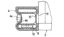
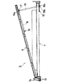
各支柱(9) は、図4に示すように、支柱支持用パイプ(4) の内側面形状に合う外側面形状を持った形態となされ、該パイプ(4) に着脱自在に差し込まれ、支柱受止め部(4a)によりパイプ(4) 内に受け止められる。
【0019】
また、支柱(9) の側壁には、所定間隔おきに多数のフック部掛止め用孔(10)が設けられている。これら多数のフック部掛止め用孔(10)のうち、所望する高さ位置にある対向するフック部掛止め用孔(10)に棚(5) のフック部(8) を引っ掛けることにより、その高さで棚(5) を取り付けることができる。
【0020】
上記運搬車を組み立てる際には、図2に示すように、各支柱支持パイプ(4) にそれぞれ支柱(9) を差し込んだ後、支柱(9) の所定高さのフック部掛止め用孔(10)に棚(5) のフック部(8) を引っ掛けて、棚(5) を支柱(9) に取り付ける。
【0021】
そして、棚板(6) の下面における支持棒(16)の両凸形部(16b) を棚受け枠(7) における保持具(18)のV形溝部(18a) 内に嵌め入れて棚(5) に傾斜をつけるか、或いは一方の凸形部(16b) を棚板(6) の下面に設けられた掛止部(19)に掛け止めて棚(5) を水平にする。棚(5) が上記傾斜状態の場合には、当該棚上の商品が見え易くなるため、商品の売れ行きが向上する。
【0022】
また、図4のように、上記棚(5) の前側枠部材(7a)に設けられた値札挟止用部材(13)間に、値札(15)を差し込むことにより、該値札(15)を垂下状態に付けることができる。
【0023】
一方、上記運搬車を使用しないときや運搬車だけを移動させるさいには、台車(1) から支柱(9) および棚(5) を取り外した後、各支柱支持パイプ(4) のスリット(11)に棚(5) の四隅のフック部(8) をそれぞれ挿入すると共に対向するスリット(11)にそれぞれ2本ずつ支柱(9) の突起(12)を挿入することにより、当該台車(1) 上に棚(5) および支柱(9) を積み重ねた状態で固定することができる。
【0024】
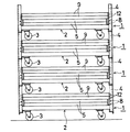
また、運搬車が複数台あるときには、図3に示すように、棚(5) および支柱(9) が積まれた上記台車(1) を積み重ねていくが、この際には、上に載せる台車(1) の各支柱支持パイプ(4) の下端部に設けられた止め片(4c)をそれぞれ下位の台車(1) の支柱支持パイプ(9) 上端部における対応する凹部(4b)にそれぞれ嵌め合わせることで、上位の台車(1) と下位の台車(1) との間に支柱支持パイプ(4) の高さ分だけのスペースが確保され、このスペースに棚(5) および支柱(9) が納められた状態となる。
【0025】
なお、上記実施例において、棚(5) の構成は種々変更できる。例えば、図7に示すように、棚受け枠(7) の前側枠部材(7a)に一定の傾斜部(S) を設け、棚板(6) を支持棒(16)を用いて傾斜させた場合に、棚板(6) の前縁部分が上記傾斜部(S) に当接するようにすることもできる。この場合、棚板(6) はより安定的に傾斜されることとなる。
【0026】
また、棚(5) のフック部(8) は、棚受け枠(7) とは別の部材としてもよい。更に、支柱(9) に設けられる多数のフック部掛止め用孔(10)は、例えば1つおきに違う形状としてもよい。このようにすれば、棚受け枠(7) を支柱(9) に水平に取り付ける作業がやりやすくなる。
【0027】
【発明の効果】
本発明の組立式運搬車によると、これを組み立てる際には、各パイプにそれぞれ支柱を差し込んだ後、支柱の所定高さのフック部掛止め用孔に棚のフック部を引っ掛けて、棚を支柱に取り付ければよいので、組立が容易である。
【0028】
また、運搬車を使用しないときや運搬車だけを移動させるさいには、台車から支柱および棚を取り外した後、各支柱支持パイプのスリットに、棚の四隅のフック部をそれぞれ挿入すると共に対向するスリットにそれぞれ2本ずつ支柱の突起を挿入することにより、当該台車上に棚および支柱を積み重ねた状態で固定することができる。そのため、棚および支柱は、台車上に安定的に積み重ねられた状態となり、しかもこれら部材を保管するためのスペースを別途に確保する必要がない。
【0029】
さらに、運搬車が複数台あるときには、上に載せる台車のパイプ下端部を下にある台車のパイプ上端部に嵌め合わせることにより、台車を安定な状態で積み重ねることができ、かつ上位の台車と下位の台車との間に棚および支柱が上述のように安定的に納められるので、複数の運搬車を格納するのに必要な床面積を少なくすることができる。
【0030】
また、積み重ねた上記の各台車を外して、必要な場所へ移動させる際にも、運搬車を組立てるのに必要な棚および支柱が台車上に滑り落ちることなく、載置された状態で一緒に持って行くことができるため、棚および支柱の管理もきわめて容易となる。
【0031】
更に、本発明では、上記棚の前縁部の下部に、互いに当接し合う2つの弾性材からなる値札挟止用部材を設け、両部材間に値札を差し込むだけで、棚に値札を付けることができる。そのため、棚上に陳列された商品の値段を明確且つ簡単に表示することが可能となる。
【図面の簡単な説明】
【図1】本発明による組立式運搬車の分解斜視図である。
【図2】同側面図である。
【図3】分解した運搬車を積み重ねた状態を示す側面図である。
【図4】図2におけるVI−VI線断面図である。
【図5】本発明の組立式運搬車における棚板の底面図である。
【図6】図2におけるVI−VI線断面図である。
【図7】図2におけるVII −VII 線断面図である。
【図8】本発明における棚受け枠の他の実施例を示す横断面図である。
【符号の説明】
(1) 台車
(2) 基台
(4) 支柱支持用パイプ
(5) 棚
(8) フック部
(9) 支柱
(10) フック部掛止め用孔
(11) スリット
(12) 突起
(13) 値札挟止用部材
(15) 値札[0001]
[Industrial application fields]
The present invention relates to an assembly-type transport vehicle.
[0002]
[Prior art]
Conventionally, as an assembly-type transport vehicle, a cart in which a plurality of pairs of front and rear support columns are fixed to the left and right on a caster base, a pair of front and rear hollow support columns inserted into the pair of front and rear support tubes, and A shelf forming member having a plurality of horizontal rails secured between the front and rear columns, and a reinforcing frame member to which a plurality of front and rear columns of column reinforcement pipes inserted into the upper end hollow portion of each column are fixed at both front and rear ends. (See Japanese Utility Model Publication No. 64-45573).
[0003]
[Problems to be solved by the invention]
The conventional assembly-type transport vehicle has the advantage that it can be assembled and disassembled. However, the shelf forming member and the reinforcing frame member removed from the cart each require considerable storage space, and in particular, there are a plurality of transport vehicles. When there were tables, the floor space required for storage could not be reduced.
[0004]
An object of the present invention is to assemble easily, reduce the storage space when not using a transport vehicle or move only the transport vehicle, and reduce the floor area required to store a plurality of transport vehicles. It is an object of the present invention to provide an assembly-type transport vehicle that can be used.
[0005]
[Means for Solving the Problems]
The assembly-type transport vehicle according to the present invention includes a carriage having a substantially rectangular base that is long in the left-right direction when viewed from the plane, and a pillar support pipe having a required length provided at four corners of the base and having pillar support portions. A plurality of pillars having lower end portions that are detachably inserted into the column support pipes and provided with hook portion hooking holes at predetermined intervals in the vertical direction and hook portions that are hooked into the hook portion hooking holes at four corners. When the carts are stacked, the lower ends of the pipes in the upper cart and the upper ends of the pipes in the lower cart are fitted together, and the columns are spaced between the pair of pipes facing each other in the left-right direction. same or in short made the length and ends only and projections are provided in pairs toward walls of each pair of pipe before and after facing the lateral direction, and two extending from its upper end downward and each Tan'nia of the strut In which the length of the slits may be inserted side by side a hook portion on each corner of the projections and Zentana in the vertical direction is provided.
[0006]
Further, in the present invention, there is provided a price tag clamping member made of two elastic materials before and after the lower part of the front edge portion of the shelf, and the price tag can be inserted between the two members from below. is there.
Further, according to the present invention, each shelf includes a shelf receiving frame provided with a hook portion and a pinching member, and a removable shelf plate that can be received both in a horizontal state and in a tilted state on the shelf receiving frame. It will be .
[0007]
[Action]
According to the assembly-type transport vehicle of the present invention, when assembling this, after inserting the support column into each support column support pipe, inserting the hook portion of the shelf into the hook portion hooking hole of a predetermined height of the support column, Attach the shelf to the column.
[0008]
When not using the transport vehicle or moving only the transport vehicle, after removing the columns and shelves from the carriage, insert the hooks at the four corners of the shelves into the slits of each column support pipe, respectively, By inserting the protrusions of the pillars two by two, the shelf and the pillars can be fixed in a stacked state on the cart.
[0009]
In addition, when there are a plurality of transport vehicles, the carts loaded with shelves and columns are stacked. At this time, the column support pipe lower end of the vehicle to be placed on the upper end of the column support pipe of the cart below By fitting together, a space corresponding to the height of the column support pipe is secured between the upper and lower carts, and the shelf and the columns are stored in this space.
[0010]
Furthermore, in the present invention, a price tag clamping member made of two elastic materials that abut each other is provided at the lower part of the front edge of the shelf, and the price tag is attached to the shelf simply by inserting the price tag between the two members. Can do.
[0011]
【Example】
Embodiments of the present invention will be described below with reference to the drawings.
[0012]
1 to 7, the transport vehicle includes a carriage (1) having a substantially rectangular base (2) that is long in the left-right direction when viewed from the plane, and four column corners of the base (2). (4a) A bottomed column support pipe (4) having a required length and a lower end portion that is detachably inserted into the column support pipe (4), and hook holes for latching at predetermined intervals in the vertical direction. (10) and a plurality of shelves (5) having hook portions (8) hooked at hook hook holes (10) at four corners (5), and the cart (1) is stacked. when the, the upper end portion of the pipe (4) in the pipe lower end and the lower carriage (4) (1) in the upper carriage (1) is fitted, struts (9), front and rear opposite to the lateral direction the slightly shorter made the length and across from the interval between each pair of pipes (4) is pivotally supported projections (12), versus direction of said each pair before and after facing the lateral direction the pipe (4) On the wall, above it Length that extends downward from the end and can be inserted with the protrusions (12) at each end of the two struts (9) and hooks (8) at each corner of the entire shelf (5) aligned vertically The slit (11) is provided.
[0013]
The dolly (1) has casters (3) attached near its four corners. A recess (4b) is provided over the entire length of the outer wall of the column support pipe (4) of the carriage (1), and a stopper piece (4c) is pivotally attached to the lower end of the recess (4b) so as to protrude downward. Yes.
[0014]
The shelf (5) is composed of a rectangular shelf board (6) and a shelf receiving frame (7) for receiving it. Among the frame members constituting the shelf receiving frame (7), at the lower part of the front frame member (7a), as shown in FIG. By providing the price tag (15) between both members, the price tag (15) is held in a suspended state.
[0015]
As shown in FIG. 1, FIG. 5 and FIG. 6, at the position near the rear edge of the shelf board (6), the concave part (16a) between the two convex parts (16b) and the two convex parts (16b). One bent support rod (16) having both end portions (16c) is provided. The support rod (16) has a concave portion (16a) and both end portions (16c) attached to the lower surface of the shelf plate (6) by a stop portion (17) so as to be swingable. ) Is fitted into the V-shaped groove (18a) of the holder (18) integrally provided on the lower surface of the rear edge of the shelf receiving frame (7), or one convex portion (16b) is provided on the shelf plate. It is configured to be latched by a corresponding latching portion (19) provided on the lower surface of (6).
[0016]
When the biconvex portion (16b) of the support rod (16) is fitted into the V-shaped groove (18a) of the holder (18) in the shelf receiving frame (7), as shown in FIGS. In addition, the shelf (6) is inclined forward. In addition, in the state where the shelf board (6) is inclined, the holding belt (21) for the display item is blocked between the two front support columns (9) as necessary.
[0017]
On the other hand, when one convex part (16b) of each support bar (16) is latched to the latching part (19), the shelf board (6) is received horizontally in the shelf support frame (7). State.
[0018]
As shown in FIG. 4, each support column (9) has an outer surface shape that matches the inner surface shape of the support column pipe (4) and is detachably inserted into the pipe (4). It is received in the pipe (4) by the receiving part (4a).
[0019]
In addition, a large number of hook portion latching holes (10) are provided at predetermined intervals on the side wall of the column (9). By hooking the hook part (8) of the shelf (5) into the hook part hooking hole (10) facing each other at the desired height position among the many hook part hooking holes (10), Shelf (5) can be mounted at height.
[0020]
When assembling the transport vehicle, as shown in FIG. 2, after inserting the struts (9) into the strut support pipes (4), the hooks for retaining the hooks (9) of the predetermined height of the struts (9) ( Hook the hook (8) of the shelf (5) on 10) and attach the shelf (5) to the column (9).
[0021]
Then, the biconvex portion (16b) of the support rod (16) on the lower surface of the shelf plate (6) is fitted into the V-shaped groove portion (18a) of the holder (18) in the shelf receiving frame (7) and the shelf ( 5) Inclination is made, or one convex part (16b) is hung on the latching part (19) provided on the lower surface of the shelf board (6) to level the shelf (5). When the shelf (5) is tilted, the products on the shelf can be easily seen, so that the sales of the products are improved.
[0022]
Further, as shown in FIG. 4, by inserting the price tag (15) between the price tag clamping members (13) provided on the front frame member (7a) of the shelf (5), the price tag (15) is inserted. Can be attached in a suspended state.
[0023]
On the other hand, when the transport vehicle is not used or when only the transport vehicle is moved, after removing the column (9) and the shelf (5) from the carriage (1), the slits (11) of each column support pipe (4) are removed. ), Insert the hooks (8) at the four corners of the shelf (5), and insert the projections (12) of the support posts (9) into the opposing slits (11). The shelf (5) and support post (9) can be fixed in a stacked state.
[0024]
In addition, when there are a plurality of transport vehicles, as shown in FIG. 3, the cart (1) loaded with the shelves (5) and the support posts (9) is stacked. Fit the stopper (4c) provided at the lower end of each column support pipe (4) of (1) into the corresponding recess (4b) at the upper end of the column support pipe (9) of the lower carriage (1). By combining them, a space corresponding to the height of the column support pipe (4) is secured between the upper cart (1) and the lower cart (1), and the shelf (5) and column (9) are secured in this space. Will be in a state of being paid.
[0025]
In the above embodiment, the configuration of the shelf (5) can be variously changed. For example, as shown in FIG. 7, a fixed inclined portion (S) is provided on the front frame member (7a) of the shelf receiving frame (7), and the shelf plate (6) is inclined using the support rod (16). In this case, the front edge portion of the shelf board (6) can be brought into contact with the inclined portion (S). In this case, the shelf board (6) is inclined more stably.
[0026]
The hook portion (8) of the shelf (5) may be a member different from the shelf receiving frame (7). Furthermore, the number of hook portion latching holes (10) provided in the support (9) may be different, for example, every other one. In this way, the work of attaching the shelf receiving frame (7) to the support (9) horizontally can be easily performed.
[0027]
【The invention's effect】
According to the assembly-type transport vehicle of the present invention, when assembling this, after inserting the support column into each pipe, the hook part of the shelf is hooked in the hook part latching hole of the predetermined height of the support column, and the shelf is Since it only needs to be attached to the column, assembly is easy.
[0028]
Also, when not using the transport vehicle or moving only the transport vehicle, after removing the columns and shelves from the carriage, insert the hooks at the four corners of the shelves into the slits of each column support pipe and face each other. By inserting two protrusions of the column into the slit, the shelf and the column can be fixed in a stacked state on the cart. Therefore, the shelf and the support column are stably stacked on the carriage, and it is not necessary to separately secure a space for storing these members.
[0029]
Furthermore, when there are multiple transport vehicles, the lower end of the pipe of the carriage to be placed on the upper end of the pipe of the lower truck can be fitted in a stable state. Since the shelves and the support columns are stably stored between the two carts as described above, the floor area required for storing a plurality of transport vehicles can be reduced.
[0030]
Also, when removing each of the above-mentioned carts and moving them to the required location, the shelves and columns required to assemble the transport vehicle will not slide down on the cart and must be held together. Management of shelves and columns is also very easy.
[0031]
Furthermore, in the present invention, a price tag clamping member made of two elastic materials that abut each other is provided at the lower part of the front edge of the shelf, and the price tag is attached to the shelf simply by inserting the price tag between the two members. Can do. Therefore, it becomes possible to display the price of the commodity displayed on the shelf clearly and easily.
[Brief description of the drawings]
FIG. 1 is an exploded perspective view of an assembly-type transport vehicle according to the present invention.
FIG. 2 is a side view of the same.
FIG. 3 is a side view showing a state in which disassembled transport vehicles are stacked.
4 is a cross-sectional view taken along line VI-VI in FIG.
FIG. 5 is a bottom view of a shelf board in the assembly-type transport vehicle of the present invention.
6 is a cross-sectional view taken along line VI-VI in FIG.
7 is a cross-sectional view taken along line VII-VII in FIG.
FIG. 8 is a cross-sectional view showing another embodiment of the shelf receiving frame in the present invention.
[Explanation of symbols]
(1) Dolly
(2) Base
(4) Support pipe
(5) Shelf
(8) Hook part
(9) Prop
(10) Hook hook hole
(11) Slit
(12) Projection
(13) Price tag clamping member
(15) Price tag
Claims (3)
Priority Applications (1)
| Application Number | Priority Date | Filing Date | Title |
|---|---|---|---|
| JP01197695A JP3663473B2 (en) | 1995-01-27 | 1995-01-27 | Assembled transporter |
Applications Claiming Priority (1)
| Application Number | Priority Date | Filing Date | Title |
|---|---|---|---|
| JP01197695A JP3663473B2 (en) | 1995-01-27 | 1995-01-27 | Assembled transporter |
Publications (2)
| Publication Number | Publication Date |
|---|---|
| JPH08198114A JPH08198114A (en) | 1996-08-06 |
| JP3663473B2 true JP3663473B2 (en) | 2005-06-22 |
Family
ID=11792643
Family Applications (1)
| Application Number | Title | Priority Date | Filing Date |
|---|---|---|---|
| JP01197695A Expired - Lifetime JP3663473B2 (en) | 1995-01-27 | 1995-01-27 | Assembled transporter |
Country Status (1)
| Country | Link |
|---|---|
| JP (1) | JP3663473B2 (en) |
Cited By (2)
| Publication number | Priority date | Publication date | Assignee | Title |
|---|---|---|---|---|
| KR20220021671A (en) * | 2020-08-14 | 2022-02-22 | 하동웅 | Display rack |
| KR20230106772A (en) * | 2022-01-06 | 2023-07-14 | 하동웅 | Display rack |
Families Citing this family (2)
| Publication number | Priority date | Publication date | Assignee | Title |
|---|---|---|---|---|
| JP3309649B2 (en) * | 1995-06-30 | 2002-07-29 | 株式会社ダイフク | Goods carrier |
| JP2000127976A (en) * | 1998-10-22 | 2000-05-09 | Honko Seisakusho:Kk | Trolley with display shelves |
-
1995
- 1995-01-27 JP JP01197695A patent/JP3663473B2/en not_active Expired - Lifetime
Cited By (4)
| Publication number | Priority date | Publication date | Assignee | Title |
|---|---|---|---|---|
| KR20220021671A (en) * | 2020-08-14 | 2022-02-22 | 하동웅 | Display rack |
| KR102413085B1 (en) * | 2020-08-14 | 2022-06-24 | 하동웅 | Display rack |
| KR20230106772A (en) * | 2022-01-06 | 2023-07-14 | 하동웅 | Display rack |
| KR102754205B1 (en) * | 2022-01-06 | 2025-01-15 | 하동웅 | Display rack |
Also Published As
| Publication number | Publication date |
|---|---|
| JPH08198114A (en) | 1996-08-06 |
Similar Documents
| Publication | Publication Date | Title |
|---|---|---|
| US5215199A (en) | Rack for supporting items such as bottles | |
| US4588096A (en) | Knock-down tray rack | |
| US8739986B2 (en) | Retail cart | |
| CA1067535A (en) | Store merchandising apparatus | |
| US6173846B1 (en) | Safety stop for pallet rack | |
| US7320472B2 (en) | Cart for stocking inventory and methods for making same | |
| US2971657A (en) | Merchandise display assembly | |
| US4632412A (en) | Combination hand truck and display stand | |
| US4938368A (en) | Merchandise display and dispenser rack | |
| CA2342373A1 (en) | Multi peg adapter device | |
| US6354612B1 (en) | Shopping cart having selectively positionable tray basket | |
| US3896936A (en) | Wine bottle rack | |
| JP3663473B2 (en) | Assembled transporter | |
| JP3535570B2 (en) | Gardening trolley | |
| JPH0711473U (en) | Prefabricated carrier | |
| JP2014153963A (en) | Counter device | |
| JPH08244622A (en) | Stock cart | |
| JP3312957B2 (en) | Horizontally connected transport equipment for plate-like objects such as glass plates | |
| JP2004026428A (en) | Assembly type arrangement rack | |
| JP3064404U (en) | Bag holder | |
| KR102849037B1 (en) | Pipe Rack Multipurpose Shelf Structure | |
| JP2724667B2 (en) | Stock cart | |
| JP3109103U (en) | Hanger pipe receiving bracket and hanger pipe receiving bracket unit. | |
| JP2724666B2 (en) | Stock cart | |
| JP3711805B2 (en) | Carriage for transportation |
Legal Events
| Date | Code | Title | Description |
|---|---|---|---|
| A977 | Report on retrieval |
Free format text: JAPANESE INTERMEDIATE CODE: A971007 Effective date: 20040601 |
|
| A131 | Notification of reasons for refusal |
Free format text: JAPANESE INTERMEDIATE CODE: A131 Effective date: 20040817 |
|
| A521 | Written amendment |
Free format text: JAPANESE INTERMEDIATE CODE: A523 Effective date: 20041015 |
|
| TRDD | Decision of grant or rejection written | ||
| A01 | Written decision to grant a patent or to grant a registration (utility model) |
Free format text: JAPANESE INTERMEDIATE CODE: A01 Effective date: 20050215 |
|
| A61 | First payment of annual fees (during grant procedure) |
Free format text: JAPANESE INTERMEDIATE CODE: A61 Effective date: 20050314 |
|
| R150 | Certificate of patent (=grant) or registration of utility model |
Free format text: JAPANESE INTERMEDIATE CODE: R150 |
|
| FPAY | Renewal fee payment (prs date is renewal date of database) |
Free format text: PAYMENT UNTIL: 20090408 Year of fee payment: 4 |
|
| FPAY | Renewal fee payment (prs date is renewal date of database) |
Free format text: PAYMENT UNTIL: 20100408 Year of fee payment: 5 |
|
| S531 | Written request for registration of change of domicile |
Free format text: JAPANESE INTERMEDIATE CODE: R313531 |
|
| FPAY | Renewal fee payment (prs date is renewal date of database) |
Free format text: PAYMENT UNTIL: 20100408 Year of fee payment: 5 |
|
| R350 | Written notification of registration of transfer |
Free format text: JAPANESE INTERMEDIATE CODE: R350 |
|
| FPAY | Renewal fee payment (prs date is renewal date of database) |
Free format text: PAYMENT UNTIL: 20110408 Year of fee payment: 6 |
|
| FPAY | Renewal fee payment (prs date is renewal date of database) |
Free format text: PAYMENT UNTIL: 20120408 Year of fee payment: 7 |
|
| FPAY | Renewal fee payment (prs date is renewal date of database) |
Free format text: PAYMENT UNTIL: 20130408 Year of fee payment: 8 |
|
| FPAY | Renewal fee payment (prs date is renewal date of database) |
Free format text: PAYMENT UNTIL: 20140408 Year of fee payment: 9 |
|
| R250 | Receipt of annual fees |
Free format text: JAPANESE INTERMEDIATE CODE: R250 |
|
| EXPY | Cancellation because of completion of term |