JP3663893B2 - Data relay system - Google Patents
Data relay system Download PDFInfo
- Publication number
- JP3663893B2 JP3663893B2 JP6114698A JP6114698A JP3663893B2 JP 3663893 B2 JP3663893 B2 JP 3663893B2 JP 6114698 A JP6114698 A JP 6114698A JP 6114698 A JP6114698 A JP 6114698A JP 3663893 B2 JP3663893 B2 JP 3663893B2
- Authority
- JP
- Japan
- Prior art keywords
- data
- relay
- stream
- multiplexed
- data stream
- Prior art date
- Legal status (The legal status is an assumption and is not a legal conclusion. Google has not performed a legal analysis and makes no representation as to the accuracy of the status listed.)
- Expired - Fee Related
Links
Images










Landscapes
- Data Exchanges In Wide-Area Networks (AREA)
- Small-Scale Networks (AREA)
- Telephonic Communication Services (AREA)
Description
【0001】
【発明の属する技術分野】
本発明は、マルチメディア通信システムにおける、データ中継装置、データ中継方法及びデータ中継多重化フォーマットに関する。
【0002】
【従来の技術】
TCP/IPをベースとするインターネットが急速に普及している。WWW(World Wide Web)という全世界的な情報通信システムがインターネットの普及にさらに拍車をかけている。
【0003】
このような背景において、インターネットに通信端末を接続し、音データをリアルタイムに送受信し、電話同様の通話を提供するインターネット電話といわれる通信システムが出始めており、通話をインターネット上に統合しようという動きが活発になってきている。特に、一般の電話機からインターネット内のアクセスポイントにアクセスし、そのアクセスポイントから電話をかけたい相手に近いアクセスポイントまでをインターネットで、相手側のアクセスポイントからは公衆電話網で電話をかけるタイプのインターネット電話が注目を浴びている。インターネット電話については、“インターネット利用の格安電話 東京ー大阪間3分55円も登場”(日経コミュニケーション 97/2/3)、“インターネット電話とテレビ電話”(PCWAVE 97/3 pp.81)にまとめられている。
【0004】
【発明が解決しようとする課題】
上記文献に記載の従来の通信システムでは、1台の音データ中継装置(GW:Gate Way)に複数の回線が収容されている場合、各回線毎に音ストリームを生成して中継処理を行っている。音情報をインターネット上に流す場合、音情報の他に、これら通信システムが独自に、あるいは標準化団体が規定したヘッダ、通信プロトコルの各レイヤが付加していくヘッダ情報等、を付加してパケット化する。音情報自体は、数十msとごく短い時間を単位としてパケット化する。このため、付加情報の方が音情報よりも数倍大きくなってしまう。ある相手先GWとの間で複数の音ストリームを中継する場合、各ストリームの付加情報の内、共通の情報が多いにもかかわらず、必要以上の帯域を取っていることになる。
【0005】
例えば、インターネットで広く用いられている通信プロトコルUDP/IPと業界標準化団体IETF(The Internet Engeneering Task Force)で規定されたリアルタイム通信プロトコルRTP(Real−Time Protocol)をベースとしたパケットを見ると、音情報は30ms分(符号化方式をG.723.1の5.3kbpsとすると)の20B、RTPヘッダが12B、UDPヘッダが8B、IPヘッダが20Bであるため、ヘッダ情報40Bは音情報の2倍のデータ長になってしまう。これに各アプリケーションが付加するヘッダ情報があれば、ヘッダが占める帯域が増加する。
【0006】
本発明の目的は、多数回線を収容するGWについて、通信先GWが同じ複数のストリームについて、多重化できるストリームについて、多重化処理を行うかどうかを通信相手のGWとネゴシエーションして、通信相手が多重化処理をサポートしているかどうかを確認するデータ中継方法及びデータ中継装置を提供することに有る。
また、本発明の他の目的は、上記データ中継装置を用い、該データ中継装置の動作状況を運用管理するためのコントロール装置を提供することにある。
【0007】
【課題を解決するための手段】
上記課題を解決するために、本発明のデータ中継装置は、多重化したストリームのパケットフォーマットに、少なくとも該パケットが多重化ストリームであるかどうかを示す識別子を有し、さらに同一通信相手との間に新たにストリームが発生した際に多重化処理を行うかどうかをネゴシエーションする手段とを備えることを特徴とする。
また、このデータ中継システムは、前記データ中継装置を運用管理するためのコントロール装置を有し、該コントロール装置は前記各データ中継装置が正常稼動しているかを監視する手段と、前記各データ中継装置の中継ログ(電話をかけてきた利用者の電話番号、電話をかけたい相手の電話番号、通話開始時刻、通話終了時刻等)、中継パケットロスや中継パケット通信遅延の状況を定期的に収集する手段と、さらには前記各データ中継装置の稼動スケジューリング情報を通知する手段とを備えることを特徴とする。
【0008】
【発明の実施の形態】
まず、本発明の実施形態について、図1ないし図9および図12ないし図19を参照して説明する。
図1は、本発明の実施形態に関わる音データ中継システムの構成例で、インターネット101と公衆電話網102との接続点に音データ中継装置(以下、GW)103が、インターネット101にコントロール装置104が、公衆電話網に電話機105あるいは通信端末106が接続されている。
図2に、GW103及びコントロール装置104の内部構成を示す。図2において、GW103は、通信プログラム等が格納されているメモリ201と、メモリ201のプログラムに基づく処理を行なうCPU202と、蓄積装置203と、インターネット101や公衆電話網102で通信を行なうための通信網インターフェース制御部204と、発信側の電話機105から受信したアナログ音データをディジタルデータヘ、通話中継相手のGW103から受信したディジタルデータをアナログ音データヘ変換するディジタルアナログ変換部205と、キーボードやマウス、ペン等の入力装置206と、ディスプレイやスピーカ等の出力装置207と、以上の各部を接続する内部バス208とにより構成される。
前記蓄積装置203には、少なくとも各GWが担当するエリアの電話番号とGWのアドレスが組で登録されている。CPU202は、メモリ201の通信プログラムを実行することで、図3に示す各制御部、300の機能を実現する。コントロール装置104は、前記GWを構成する機能のうち、ディジタルアナログ変換部205以外を有する。
【0009】
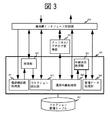
図3に示す、GW103の通信制御部300は、電話機接続処理部301、検索部302、コネクション設定部303、通話中継処理部304、中継状況処理部305、管理データ処理部306、コネクション管理テーブル307により構成される。
通信制御部300において、電話機接続処理部301は、公衆電話網102から電話機105がアクセスしてきた場合は通話相手の電話番号を取得し、前記電話機105から通話終了通知を受信した場合は通話中継処理を終了してコネクションを切断する。検索部302は、通話中継要求を受信した場合、上記接続要求に含まれる相手電話機105の電話番号から前記蓄積装置203内に格納されている通話相手の端末を収容するGWのアドレス情報を検索する。コネクション設定部303は、通話中継相手のGWとの間のコネクションを設定し、通話中継相手のGW103から通話終了通知を受信した場合は通話中継処理を終了してコネクションを切断する。通話中継処理部304は、前記ディジタルアナログ変換部205においてディジタル化された音データを通話中継相手のGW103へ中継する。中継状況処理部305は、IPパケット通信遅延やパケットロス等の中継品質を監視し、定期的に再計算する。管理データ処理部306は、前記コントロール装置104からのスケジュール情報や通信中継パラメータ等の管理データを受付ける。コネクション管理テーブル307は、中継中の音データストリームの中継先GW103のアドレス、該音データストリームは多重化対象かどうか、どの回線が使用されているか、どの回線が使用できないか等を格納するテーブルである。
【0010】
図4は、前記通話中継処理部304の内部構成を示す図で、通話中継処理部304は、前記ディジタルアナログ変換部205より受け取るディジタルデータを一時格納する入力バッファ402と、入力バッファ402内に格納されているデータの内で行き先が同じデータを多重化する多重化処理部403と、多重化処理を実行するタイミングを保持する多重化タイミング取得部404と、多重化タイミング取得部404が参照する現在時刻情報を入手する時刻入手部405と、多重化したストリームあるいは各ストリームデータを通信網インタフェース制御部204を介してインターネット101へ送信する送信処理部406と、通信網インタフェース制御部204を経由してインターネット101からデータを受信する受信処理部407と、受信したデータが多重化ストリームの場合に各ストリームへ分解する分解処理部408と、分解処理部408において各ストリームへ分けられたデータをディジタルアナログ変換部205へ出力する前に一時格納する出力バッファ409により構成される。
ディジタルアナログ変換部205においては、アナログデータをディジタルデータへ変換して圧縮処理を行う符号化処理部401と、圧縮ディジタルデータを伸長してアナログデータへ変換する復号化処理部410とを有する。
【0011】
図5は、前記中継状況処理部305の内部構成を示す図で、中継状況処理部305は、現在時刻を入手する時刻入手部501と、前記受信処理部407により受信したIPパケットが前記分解処理部408にて各ストリームへ分解された後、各ストリームデータのロスを検出するパケットロス検出部502と、該ストリームデータが遅延しているかどうかを判定するパケット遅延判定部503と、パケットロス検出部502およびパケット遅延判定部503より音データ中継状況を取得し、前記コントロール装置104に中継状況を通知するデータを加工し、生成する中継状況通知処理部504により構成される。
【0012】
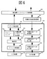
図6に示す、コントロール装置104の通信管理部600は、イベント取得部601、解析部602、中継品質パラメータ生成部603、スケジューリング604、データ転送部605、中継状況データ収集部606、中継状況データ加工部607、中継状況データ出力部608により構成される。通信制御部600において、イベント取得部601は、該コントロール装置104を使用する運用管理者が前記入力装置206を用いて何らかのイベントを入力した場合、該イベントを取得する。解析部602は、イベント取得部601により取得したユーザ入力イベントを解析し、内容によって各々処理する処理部へ振り分ける。例えば、入力されたイベントがあるGW103の稼動スケジュール変更要求コマンドであった場合、スケジューリング処理を行うスケジューリング処理部604へ、該稼動スケジュール変更要求コマンドを渡す。中継品質パラメータ生成部603は、入力されたイベントが前記解析部602により解析された結果、あるGW103への中継品質に関するコマンドである場合、要求に対する中継品質を表わすパラメータを生成する。スケジューリング処理部604は、入力されたイベントが前記解析部602により解析された結果、あるGW103へのスケジューリングに関するコマンドである場合、要求に対するスケジュール設定、変更等の該GW103へのコマンドを生成する。データ転送部605は、中継品質パラメータ生成部603あるいはスケジューリング処理部604から、各GW103への何らかのデータ転送要求を受けた場合、該データを該GW103へ送信する。中継状況データ収集部606は、各GW103より定期的に送信されてくる中継状況データを受付ける。中継状況データ加工部607は、中継状況データ収集部606により集められた各GW103のIPパケット中継状況データを出力装置207に出力する形式にするために解析し、加工する。中継状況データ出力部608は、前記中継状況データ加工部607により解析し、加工されたデータを出力装置207への出力処理を行う。例えば、出力装置としてディスプレイを用いている場合、ディスプレイへの表示処理を行う。
【0013】
GW103が送受信するIPパケットに格納する中継音データのパケットフォーマットの例を、図12ないし図18に示す。
図12において、1201は本パケットがネットワーク上を流れる際のハードウェアが付加するヘッダ情報であり、例えばEthernetに接続している場合は、Ethernetのヘッダが付加される。1202はIPレイヤが付加するヘッダ、1203はUDPレイヤが付加するヘッダ、1204は当該中継音パケットが多重化した音データを格納していることを示す識別子、1205は多重化した各音データの識別子、1206は多重化した各音データの音データのサイズ、1207は多重化した各音データである。多重化しない場合は、1201から1203までのヘッダ情報が1207の音データに対して別個に付加されることになる。
図13は、図12の中継音パケットフォーマットの代替フォーマットの例である。1301は多重化されている各音データの符号化方式を示す識別子である。
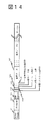
図14は、図12あるいは図13の中継音パケットフォーマットの代替フォーマットの例である。1401は該中継音パケットに多重化されているストリーム数を示す。
図15は、図12ないし図14の中継音パケットフォーマットの代替フォーマットの一例である。1501は該中継音パケットのパケットサイズを示す。なお該パケットサイズには、1201ないし1203までのヘッダのサイズは含まなくてもよい。
図16は、図12ないし図15の中継音パケットフォーマットの代替フォーマットの一例である。1601は該中継音パケットに多重化されている各音ストリームにおけるシーケンス番号を示す。
図17は、図12ないし図16の中継音パケットフォーマットの代替フォーマットの一例である。1701は該中継音パケットに多重化されている各音ストリームにおける音データの発生タイムスタンプを示す。
【0014】
図18は、図12ないし図16の中継音パケットフォーマットの代替フォーマットの一例である。本中継音パケットフォーマットは、標準化団体IETFにおいて規定されているリアルタイムプロトコルRTPをベースにしたものである。1801はRTPのバージョン情報、1802は該RTPパケット内パディングデータの有無、1803は該RTPパケットのヘッダ部分が拡張されているかどうか示すエリア、1804はマルチキャスト環境での参加ホスト数、1805はマーカビット、1806は該RTPパケットに格納されているデータのペイロードタイプを示し、多重化パケットの場合は多重化ストリームを格納していることを示すペイロードタイプを示す。1801ないし1806は標準RTPフォーマットである。1807ないし1812までは多重化されている内の各音ストリームに関するエリアであり、多重化ストリーム数分1807ないし1812までが繰り返される。1807は各音ストリームのペイロードタイプ(主に符号化方式を示す)を示すものであり、例えば音データや映像データの場合、符号化方式を示す。1808は各音ストリームにおけるシーケンス番号、1809は各音ストリームにおけるタイムスタンプ、1810は各音ストリームの発信者識別子、1811は各音ストリームにおける音データのデータサイズ、1812は各音ストリームにおける音データである。1801の前にUDP、IP、ネットワーク各ヘッダが付く。
【0015】
図19は、コネクション管理テーブル307のフォーマットの一例で、使用回線番号1901は前記GWが収容する回線のシーケンス番号、1902は現在この回線が使用されているかどうかを示し、1903はこの回線が現在使用可能かどうかを示し、1904はこの回線の通話中継における通信遅延時間の許容時間を、1905はこの回線のディジタル音データ送信用のポート番号を、1906は中継相手から中継されてくるディジタル音データ受信用のポート番号を、1907は送信しているディジタル音データストリームの識別子を、1908は中継先のGWのIPアドレスを、1909は該ディジタル音データストリームが多重化対象ストリームであるかどうかを示し、1910は該ディジタル音データストリームの識別子を、1911は該ディジタル音データストリームのIPパケットロス率を、1912は該ディジタル音データストリームのIPパケットの平均通信遅延時間を、1913は該ディジタル音データの符号化方式を示す。前記ロス率1911や平均遅延時間1912は、前記中継状況処理部305にて定期的に再計算し、前記コントロール装置へ中継品質状況データとして通知する。
【0016】
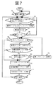
図7、図8に、GW103の通話中継処理部304の処理の流れの一例を示す。図7は、インターネット101への発信側処理の流れを示し、図8は、インターネット101からの着信側処理の流れを示す。
図7において、GW103は、前記蓄積装置203に格納されているGW通話中継プログラムが起動される等で通話中継処理が開始されると(ステップ701)、複数の前記ディジタルアナログ変換処理部205の内の各符号化処理部401から符号化データを取得したら、取得データが複数ストリームあるのかどうかを検出し(ステップ702、yes)、取得した1つ以上のデータを前記入力バッファ402へ一時格納する(ステップ703)。現在時刻を入手し(ステップ704)、多重化タイミングになった場合(ステップ705、yes)、前記入力バッファ402内に取得したデータが存在するかどうかを検出し(ステップ706、yes)、データがある場合は一つデータを取り出す(ステップ707)。
取り出したデータが前記コネクション管理テーブル307より中継先のGW103への最初のストリームの場合(ステップ708、yes)、中継先GW103のアドレス情報や、送信する音データに関するヘッダを付加してパケットを生成する(ステップ711)。ステップ711で生成したパケットを前記送信処理部406へ渡し(ステップ712)、通信プロトコルTCP(UDP)/IPを用いてインターネット101へ送信する(ステップ713)。一方、ステップ708において、既に同じ中継先GW103へのストリームが存在する場合、既に多重パケット化パケットへの多重化処理をしたデータのうちで同じ中継先GW103へのストリームに対応するデータが存在するかどうかを検出し、該当するデータが存在する場合(ステップ709、yes)、該当するパケットへ多重化する(ステップ710)し、ステップ706以降の処理を実行する。GW通話中継プログラム終了等のなんらかの終了通知を受けた場合(ステップ714、yes)、一連の処理を終了する。
【0017】
図8において、GW103は、通話中継処理が開始されると(ステップ801)、インターネット101からのパケット通信遅延の判定基準値を初期化し(ステップ802)、インターネット101からのパケット到着を監視して、パケットの受信を待つ。パケットを受信した場合(ステップ803、yes)、受信パケットが多重化パケットかどうかを判定し、多重化パケットの場合(ステップ804、yes)、前記分解処理部408において各ストリームに分解し(ステップ805)、1ストリームになったデータを前記出力バッファ409へ一時格納する(ステップ806)。現在時刻を入手し(ステップ807)、前記復号化処理部410への出力タイミングになるまで格納しておき、出力タイミングになった場合は(ステップ808、yes)、復号化処理部410へデータを出力し、復号化してディジタルデータをアナログデータへ変換する(ステップ809)。
前記中継状況処理部305にて、受信パケットに格納されている情報、例えばシーケンス番号やタイムスタンプからパケットロスがあったかどうかを検出する(ステップ810)。さらに、該パケットが遅延しているかどうかをステップ802にて設定した判定基準と比較することにより、遅延の有無を判定する(ステップ811)。ステップ807にて入手した現在時刻より、前記コントロール装置104への中継状況データ通知タイミングになった場合(ステップ812、yes)、ステップ810およびステップ811にて検出したパケットロス、パケット遅延状況の通知データを生成して前記コネクション管理テーブル307へデータを更新し(ステップ813)、前記コントロール装置104へ送信する(ステップ814)。
【0018】
図9は、コントロール装置104の通信処理部600の処理の流れの一例を示す図で、コントロール装置104は、前記蓄積装置203に格納されている音中継コントロールプログラムが起動される等で中継運用管理が開始されると(ステップ901)、各GW103それぞれに中継用初期パラメータを設定し、送信する(ステップ902)。該中継用パラメータは、例えば、メンテナンスのため2:00am..に中継処理を一時停止する等のスケジューリングに関するものであったり、IP音パケットの通信遅延の許容範囲や、あるGW103の中継品質が悪化しているため、該GW103がサポートする回線数を減少させる等の中継品質に関するもの、その他該音中継システムを運用する上で必要なデータを示す。該コントロール装置104を管理する運用管理者より、前記入力装置206を通して、何らかのイベント入力があったかどうかを検出し、イベントが入力された場合(ステップ903、yes)、該イベントを取得する(ステップ904)。
ステップ904にて取得したイベントの内容を解析し(ステップ905)、イベントに含まれている該当GW103に対して、イベント内容による制御データを生成し、TCP/IPで必要なヘッダ情報を付加してパケット化する(ステップ906)。ステップ906にて生成された制御情報データを、前記データ転送部605にて該当GW103に対し送信する(ステップ907)。また、各GW103より、中継状況通知を受信したかどうかを監視し、中継状況通知を受信した場合(ステップ908、yes)、各GW103対応に該中継状況通知から中継状況データを収集し、解析する(ステップ909)。ステップ909にて解析された中継状況データは、該コントロール装置を104を運用する運用管理者が必要とする情報へ加工し(ステップ910)、加工したデータを、該コントロール装置104が有する出力装置207で出力可能な形式へ変換し、例えばディスプレイ表示の場合は、加工した中継状況データを表示プログラムが扱えるように処理し(ステップ911)、該出力装置207へ出力する(ステップ912)。
【0019】
本実施形態の音データ中継システムによれば、前記コントロール装置が各GWの中継品質状況を監視し、回線やGWダウン等トラブル発生時や、各GWへの稼動スケジューリング等を管理することが可能となる。
【0020】
次に、本発明の他の実施形態を図10、図11を参照して説明する。
【0021】
本実施形態の音データ中継装置は、中継先が同じ音データ中継装置のストリームが発生した場合、中継先の音データ中継装置と該ストリームを多重化するかどうかをネゴシエーションする処理を上記実施形態のGW103に追加したものである。本方式を実現するシステムの全体構成や、GW、コントロール装置の処理などは、上記実施形態(図1ないし図9、図12ないし図19)と同じである。
【0022】
図10は、本実施形態のGW103のコネクション設定部303の内部構成を示す図で、前記電話機接続処理部301にて電話機105から中継要求を受けつけた場合、前記検索部302にて中継先GW103を検索した結果得られた該当GW103のアドレス情報を入手して、該GW103に対してインターネット101を介して接続要求の発信処理を行う接続要求発信処理部1001と、中継着信側GW103において、前記発信側GW103からの接続要求を受付ける接続要求着信処理部1002と、自GW103に接続している電話機105あるいは中継相手のGW103からの接続終了通知を受付け、コネクションの切断処理を行う接続終了着信処理部1003と、前記接続要求発信処理部1001あるいは前記接続要求着信処理部1002において受け付けた新規コネクションを設定する際に、該コネクションは多重化処理を行うかどうかの判定を行い、中継先GW103との間でネゴシエーションを行う多重化判定部1004とを有する。
【0023】
図11は、本実施形態のGW103のコネクション設定部303の発信側の処理の流れの一例を示す図で、ステップ701で通話中継処理が開始された後に、ある電話機105より電話がかかってきて、新規中継ストリーム要求が発生した場合(ステップ1101、yes)、前記多重化判定部1004において中継先GW103との間で、該ストリームは多重化処理を行うかどうかをネゴシエーションする(ステップ1102)。ステップ709で中継先が同じGW103へのデータが存在する場合(ステップ708、yes)、当該ストリームは多重化処理対象ストリームかどうかを判定し、多重化処理対象ストリームの場合(ステップ1103、yes)、以降の一連の多重化処理を行う。
【0024】
なお、多重化処理のネゴシエーション方式には、あらかじめ定めておくコマンドをやり取りする方式以外にも、音情報の圧縮方式のネゴシエーション時に合わせて行ったり、また各IPパケットのヘッダ部分のバージョン情報を含める等で行っても良い。
本実施形態の音データ中継装置によれば、各中継ストリームを多重化するか否かをあらかじめ中継先GW103とネゴシエーションするため、多重化処理をサポートしてない音データ中継装置との間でも電話呼の中継を行うことが可能となる。
【0025】
次に、本発明のさらに他の実施形態を図20ないし図23を参照して説明する。
本実施形態の音データ中継装置は、多重化データを送受信する場合、該多重化データに含まれるいづれかの音ストリームに割り当てられているUDPポートを使用して送受信する処理を、上記実施形態のGW103に追加したものである。本方式を実現するシステムの全体構成や、GW、コントロール装置の処理、パケットフォーマットなどは、上記実施形態と同じである。
図20は、本実施形態のGW103の通話中継処理部304の内部構成を示す図で、多重対象の複数の音データを格納できるサイズを持つ、自GW103が収容する回線数分あるいはさらに多重化データ用に該音データ中継システムに設置されているGW103の設置数分の送信バッファ2001と、前記受信処理部407において受信した多重データあるいは単一の音データを一時格納する受信バッファ2002とをさらに有する。
【0026】
図21は、本実施形態のGW103の発信側の処理の流れの一例を示す。
図21において、ステップ701で通話中継処理が開始された後、自GW103が収容する回線数分の送信バッファを初期化する(ステップ2101)。各回線に対応する送信バッファのサイズは、ネットワーク上でセグメント化されない値とする。該送信バッファにバッファリング(多重)される音データ数は、各音データの符号化方式により1ストリーム時のパケット単位サイズが異なるため、不定である。ステップ709にて、取得した音データについて、中継先GW103が同じ音データが存在すると判定された場合、該取得音データのヘッダ情報を付加し(ステップ2102)、該音データの中継先GW103に対する前記送信バッファ2001へキューイングする(ステップ2103)。ステップ2102で各音データに付加するヘッダ情報は、例えばパケットフォーマットを図18で示したRTP拡張フォーマットを取る場合、ペイロードタイプ1807に該音データの音符号化方式、例えばG.723.1を用いている場合は「12」を、シーケンス番号1808に該音データ送信を開始してからのパケットシーケンス番号を、タイムスタンプ1809に該音データ送信を開始してからの音データのサンプル数を、SSRC1810に該音データの送信者識別子を、サイズ1811に該音データのデータサイズを設定する。この場合、ステップ711で付加するヘッダ情報は、RTPで規定されているヘッダ情報のうちで、バージョン情報1801と、パディングの有無1802と、拡張の有無1803と、貢献者数1804と、マーカビット1805、多重の有無1806の6つの情報を示す。
ステップ2103で多重対象データをキューイングする送信バッファ2001は、既に送信バッファへのキューイング処理が終了している、同じ中継先へのデータがキューイングされている送信バッファを使用し、処理済の音データに続けてキューイングする。多重データの送信に用いるUDPポートは、該多重対象データをキューイングした送信バッファに対応している中継ストリームに割り当てられているものを使用する。あるいは、多重データがキューイングされている送信バッファの最後にキューイングされた多重対象データに割り当てられているものを使用しても良い。
なお、UDPポートの扱いに関して、送信及び受信それぞれに使用するUDPポートを常に同じに値に設定すれば、単一ストリーム、多重化ストリームに関わらず、送信、受信それぞれ一つずつのUDPポートを使用することもできる。この際、送信ポート、受信ポートは別ではなく同じでも構わない。
【0027】
図22に、本実施形態のGW103の多重化データの送受信に使用するUDPポートの設定方法の変形例の発信側の処理の流れの一例を示す。本処理は、多重化データ用のUDPポートを、該音データ中継システム内に設置されているGW103の設置数分持ち、多重化データが発生した場合、単一のストリームとして送受信に使用していたUDPポートから、該多重化用のUDPポートに変更するものである。
図22において、ステップ701で通話中継処理が開始された後、自GW103が収容する回線数と該音データ中継システム内に設置されているGW103の設置数分の送信バッファ2001を初期化し、送信バッファ2001数分のUDPポートを確保する(ステップ2201)。この際、各多重化データ送受信用のポートと当該ポートを使用する中継先の音データ中継装置のIPアドレスとを対応づけて組として保持する。
ステップ709にて、取得したデータと同じ中継先GW103のデータが存在すると判定した場合、ステップ2102において取得データに対して該取得データに対応するヘッダ情報を付加した後、ステップ709にて判定された中継先GW103が同じデータを中継先GW103に対応する多重化用の送信バッファ2001へ移行し、該取得データを同じ多重化用の送信バッファ2001へキューイングする(ステップ2202)。この際、取得データが、多重対象ストリームの3本目以降のストリームである場合、既に2本目のストリームまでの多重化用送信バッファ2001への移行は処理されているため、取得データのみのキューイング処理を行う。
【0028】
本実施形態の音データ中継装置によれば、図21の送信方法の場合は、多重化用のリソース(ポート、バッファ)を特に必要とせず、各ストリームを個別に送信する場合と同じリソースで多重ストリームを中継することが可能である。図22の送信方法の場合は、多重化ストリームと単一ストリームのUDPポートが分けられているため、例えば、多重化ストリームに割り当てられているポート番号を使用することにより、多重化ストリームへの優先制御や帯域制御を容易に行うことが可能である。
【0029】
以上説明した各実施形態においては、音データについて述べたが、これに限らず、ディジタル化された各種マルチメディアデータたとえば、動画データ、または、音と動画とを含むデータに、同様に適用できることは明らかである。
上述の各実施形態を実現するプログラムは、フロッピーディスク、CD−ROMなどの記憶媒体に格納して配付することが可能である。
【0030】
【発明の効果】
本発明によれば、多数の回線を収容するGWについて、あるGW間にストリーム中継要求が発生した場合、該ストリームの多重化処理を行うかどうかをネゴシエーションすることにより、多重化機能を持たないGWとの単独ストリームの相互接続が可能となる。
【図面の簡単な説明】
【図1】本発明の実施形態に係る音データ中継装置の全体構成図である。
【図2】GWおよびコントロール装置の構成図である。
【図3】GWの通信制御部の構成図である。
【図4】GWの通話中継処理部の構成図である。
【図5】GWの中継状況処理部の構成図である。
【図6】コントロール装置の通信制御部の構成図である。
【図7】GWの通話中継処理部のインターネットへの発信側処理の流れ図である。
【図8】GWの通話中継処理部のインターネットからの受信側処理の流れ図である。
【図9】コントロール装置の中継状況管理処理の流れ図である。
【図10】他の実施形態のGWのコネクション設定部の構成図である。
【図11】他の実施形態のGWのコネクション設定部および通話中継処理部のインターネットへの送信側処理の流れ図である。
【図12】本発明の実施形態に用いる中継音パケットフォーマット例である。
【図13】本発明の実施形態に用いる中継音パケットフォーマット例である。
【図14】本発明の実施形態に用いる中継音パケットフォーマット例である。
【図15】本発明の実施形態に用いる中継音パケットフォーマット例である。
【図16】本発明の実施形態に用いる中継音パケットフォーマット例である。
【図17】本発明の実施形態の中継音パケットフォーマット例である。
【図18】本発明の実施形態の中継音パケットフォーマット例である。
【図19】本発明の実施形態に用いるコネクション管理テーブルフォーマットの一例である。
【図20】本発明の実施形態に用いる通話中継処理部の構成図である。
【図21】他の実施形態のGWの通話中継処理部のインターネットへの送信側処理の一例である。
【図22】他の実施形態に用いるGWの通話中継処理部のインターネットへの送信側処理の一例である。
【符号の説明】
101・・・インターネット、102・・・公衆電話網、103・・・GW、104・・・コントロール装置、300・・・通信制御部、303・・・コネクション設定部、304・・・通話中継処理部、600・・・通信管理部。[0001]
BACKGROUND OF THE INVENTION
The present invention relates to a data relay device, a data relay method, and a data relay multiplexing format in a multimedia communication system.
[0002]
[Prior art]
The Internet based on TCP / IP is rapidly spreading. A worldwide information communication system called WWW (World Wide Web) has further spurred the spread of the Internet.
[0003]
In such a background, a communication system called an Internet phone that connects a communication terminal to the Internet, transmits and receives sound data in real time, and provides a call similar to a telephone has started to appear, and there is a movement to integrate the call on the Internet. It is becoming active. In particular, you can access an access point in the Internet from a general telephone, and use the Internet from the access point to the access point close to the other party you want to call, and from the other access point to the public telephone network. Telephone is drawing attention. As for Internet phone calls, it is summarized in “Cheap phone calls using the Internet between Tokyo and Osaka for 3 minutes 55 yen” (Nikkei Communication 97/2/3) and “Internet phone and videophone” (PCWAVE 97/3 pp. 81). It has been.
[0004]
[Problems to be solved by the invention]
In the conventional communication system described in the above document, when a plurality of lines are accommodated in one sound data relay apparatus (GW: Gate Way), a sound stream is generated for each line and relay processing is performed. Yes. When sound information is transmitted over the Internet, in addition to sound information, these communication systems add packets, such as headers specified by standardization organizations, header information added by each layer of the communication protocol, etc. To do. The sound information itself is packetized in units of a very short time of several tens of ms. For this reason, the additional information is several times larger than the sound information. When a plurality of sound streams are relayed to a certain destination GW, a band more than necessary is taken although there is much common information among the additional information of each stream.
[0005]
For example, a packet based on the real-time communication protocol RTP (Real-Time Protocol) defined by the communication protocol UDP / IP widely used in the Internet and the industry standardization organization IETF (The Internet Engineering Task Force) Since the information is 20B for 30 ms (encoding scheme is 5.3 kbps of G.723.1), the RTP header is 12B, the UDP header is 8B, and the IP header is 20B, the header information 40B is 2 of the sound information. Double the data length. If there is header information added by each application, the bandwidth occupied by the header increases.
[0006]
An object of the present invention is to negotiate with a communication partner GW whether or not to perform multiplexing processing on a stream that can be multiplexed for a plurality of streams having the same communication destination GW for a GW that accommodates a large number of lines. An object of the present invention is to provide a data relay method and a data relay apparatus for confirming whether or not multiplexing processing is supported.
Another object of the present invention is to provide a control device for managing the operation status of the data relay device using the data relay device.
[0007]
[Means for Solving the Problems]
In order to solve the above-mentioned problem, the data relay apparatus of the present invention has at least an identifier indicating whether or not the packet is a multiplexed stream in the packet format of the multiplexed stream, and further, between the same communication partner. And a means for negotiating whether or not to perform multiplexing processing when a new stream is generated.
The data relay system further includes a control device for operating and managing the data relay device, the control device monitoring whether each data relay device is operating normally, and each data relay device. Periodically collect the status of relay log loss and relay packet communication delay (such as the telephone number of the user who made the call, the telephone number of the other party who wants to call, the call start time, the call end time, etc.) And means for notifying operation scheduling information of each data relay apparatus.
[0008]
DETAILED DESCRIPTION OF THE INVENTION
First, an embodiment of the present invention will be described with reference to FIGS. 1 to 9 and FIGS. 12 to 19.
FIG. 1 is a configuration example of a sound data relay system according to an embodiment of the present invention. A sound data relay device (hereinafter referred to as GW) 103 is connected to a connection point between the Internet 101 and the
FIG. 2 shows the internal configuration of the GW 103 and the control device 104. In FIG. 2, a GW 103 includes a
In the
[0009]
The
In the
[0010]
FIG. 4 is a diagram showing an internal configuration of the call
The digital-
[0011]
FIG. 5 is a diagram illustrating an internal configuration of the relay
[0012]
6, the communication management unit 600 of the control device 104 includes an
[0013]
Examples of the packet format of the relay sound data stored in the IP packet transmitted / received by the
In FIG. 12,
FIG. 13 is an example of an alternative format of the relay tone packet format of FIG.
FIG. 14 is an example of an alternative format of the relay sound packet format of FIG. 12 or FIG. Reference numeral 1401 denotes the number of streams multiplexed in the relay sound packet.
FIG. 15 is an example of an alternative format of the relay tone packet format of FIGS.
FIG. 16 shows an example of an alternative format of the relay tone packet format of FIGS.
FIG. 17 is an example of an alternative format of the relay tone packet format of FIGS. Reference numeral 1701 denotes a sound data generation time stamp in each sound stream multiplexed in the relay sound packet.
[0014]
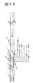
FIG. 18 is an example of an alternative format of the relay tone packet format of FIGS. This relay tone packet format is based on the real-time protocol RTP defined in the standardization organization IETF. 1801 is RTP version information, 1802 is the presence / absence of padding data in the RTP packet, 1803 is an area indicating whether the header portion of the RTP packet is expanded, 1804 is the number of participating hosts in the multicast environment, 1805 is a marker bit,
[0015]
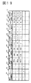
FIG. 19 shows an example of the format of the connection management table 307. The used
[0016]
7 and 8 show an example of the processing flow of the call
In FIG. 7, when the
If the extracted data is the first stream from the connection management table 307 to the relay destination GW 103 (
[0017]
In FIG. 8, when call relay processing is started (step 801), the
The relay
[0018]
FIG. 9 is a diagram showing an example of the processing flow of the communication processing unit 600 of the control device 104. The control device 104 performs relay operation management when the sound relay control program stored in the
The content of the event acquired in step 904 is analyzed (step 905), control data based on the event content is generated for the
[0019]
According to the sound data relay system of the present embodiment, the control device can monitor the relay quality status of each GW, and manage troubles such as a line or GW down, operation scheduling to each GW, and the like. Become.
[0020]
Next, another embodiment of the present invention will be described with reference to FIGS.
[0021]
The sound data relay device according to the present embodiment performs a process of negotiating whether or not to multiplex the stream with the sound data relay device of the relay destination when the stream of the sound data relay device with the same relay destination is generated. This is added to the
[0022]
FIG. 10 is a diagram showing an internal configuration of the
[0023]
FIG. 11 is a diagram illustrating an example of a processing flow on the calling side of the
[0024]
In addition to the method of exchanging predetermined commands, the negotiation method of multiplexing processing is performed in accordance with the negotiation of the sound information compression method, and includes the version information of the header portion of each IP packet. You may go in.
According to the sound data relay apparatus of this embodiment, since it is negotiated with the
[0025]
Next, still another embodiment of the present invention will be described with reference to FIGS.
When transmitting / receiving multiplexed data, the sound data relay apparatus according to the present embodiment performs a process of transmitting / receiving using a UDP port assigned to any sound stream included in the multiplexed data. It is added to. The overall configuration of the system that implements this method, the processing of the GW, the control device, the packet format, and the like are the same as in the above embodiment.
FIG. 20 is a diagram illustrating an internal configuration of the call
[0026]
FIG. 21 shows an example of the processing flow on the transmission side of the
In FIG. 21, after the call relay process is started in
The
Regarding the handling of UDP ports, if the same UDP port is used for both transmission and reception, the same UDP port is used for each transmission and reception regardless of whether the stream is a single stream or a multiplexed stream. You can also At this time, the transmission port and the reception port are not different and may be the same.
[0027]
FIG. 22 shows an example of the processing flow on the transmission side in a modified example of the method for setting the UDP port used for transmission / reception of multiplexed data of the
In FIG. 22, after the call relay processing is started in
If it is determined in
[0028]
According to the sound data relay apparatus of the present embodiment, in the case of the transmission method of FIG. 21, no multiplexing resources (ports, buffers) are particularly required, and multiplexing is performed with the same resources as when each stream is individually transmitted. It is possible to relay the stream. In the case of the transmission method of FIG. 22, since the multiplexed stream and the UDP port of the single stream are separated, for example, priority is given to the multiplexed stream by using the port number assigned to the multiplexed stream. Control and bandwidth control can be easily performed.
[0029]
In each of the embodiments described above, sound data has been described. However, the present invention is not limited to this, and various digital data such as moving image data or data including sound and moving images can be similarly applied. it is obvious.
A program that realizes each of the above-described embodiments can be stored and distributed in a storage medium such as a floppy disk or a CD-ROM.
[0030]
【The invention's effect】
According to the present invention, for a GW that accommodates a large number of lines, when a stream relay request occurs between certain GWs, a GW that does not have a multiplexing function is negotiated by deciding whether or not to perform multiplexing processing of the stream. Can be connected in a single stream.
[Brief description of the drawings]
FIG. 1 is an overall configuration diagram of a sound data relay device according to an embodiment of the present invention.
FIG. 2 is a configuration diagram of a GW and a control device.
FIG. 3 is a configuration diagram of a communication control unit of a GW.
FIG. 4 is a configuration diagram of a call relay processing unit of a GW.
FIG. 5 is a configuration diagram of a relay status processing unit of a GW.
FIG. 6 is a configuration diagram of a communication control unit of the control device.
FIG. 7 is a flowchart of processing on the outgoing call side to the Internet by the call relay processing unit of the GW.
FIG. 8 is a flowchart of processing on the reception side from the Internet of the call relay processing unit of the GW.
FIG. 9 is a flowchart of relay status management processing of the control device.
FIG. 10 is a configuration diagram of a connection setting unit of a GW according to another embodiment.
FIG. 11 is a flowchart of processing on the transmission side to the Internet of a connection setting unit and a call relay processing unit of a GW according to another embodiment.
FIG. 12 is an example of a relay sound packet format used in the embodiment of the present invention.
FIG. 13 is an example of a relay sound packet format used in the embodiment of the present invention.
FIG. 14 is an example of a relay sound packet format used in the embodiment of the present invention.
FIG. 15 is an example of a relay sound packet format used in the embodiment of the present invention.
FIG. 16 is an example of a relay sound packet format used in the embodiment of the present invention.
FIG. 17 is an example of a relay sound packet format according to the embodiment of the present invention.
FIG. 18 is an example of a relay tone packet format according to the embodiment of the present invention.
FIG. 19 is an example of a connection management table format used in the embodiment of the present invention.
FIG. 20 is a configuration diagram of a call relay processing unit used in the embodiment of the present invention.
FIG. 21 is an example of a transmission side process to the Internet of a call relay processing unit of a GW according to another embodiment.
FIG. 22 is an example of a process on the transmission side to the Internet of a call relay processing unit of a GW used in another embodiment.
[Explanation of symbols]
DESCRIPTION OF SYMBOLS 101 ... Internet, 102 ... Public telephone network, 103 ... GW, 104 ... Control apparatus, 300 ... Communication control part, 303 ... Connection setting part, 304 ... Call relay process Part, 600... Communication management part.
Claims (4)
前記第1のデータ中継装置は、
前記第1の公衆電話網に接続された前記通信端末から、前記第2の公衆電話網に接続された前記通信端末へのデータ通信要求を受信した際に、前記第2の公衆電話網と前記インターネットとを接続する前記第2のデータ中継装置を特定する手段と、
前記第2のデータ中継装置が、多重化されたデータストリームをサポートしているか否かに基づき、新たなデータ通信要求が発生した場合に、当該新たなデータ通信要求に基づく新たなデータストリームの多重化処理を行うか否かについて、前記第2のデータ中継装置とネゴシエーションする手段と、
当該第1のデータ中継装置から、特定した前記第2のデータ中継装置へ、他のデータストリームを中継中であるか否かを調べる手段と、
前記他のデータストリームを中継中であり、前記ネゴシエーションの結果、多重化処理を行うと判断した場合に、中継中である前記他のデータストリームと、前記新たなデータ通信要求に基づく前記新たなデータストリームとの多重化処理を行う手段と、
前記第2のデータ中継装置へ、前記多重化処理を行ったデータストリームを中継する手段と、
中継中の前記他のデータストリームに前記新たな通信要求に基づく多重化処理を行わないと判断した場合には、前記第2のデータ中継装置へ、前記新たな通信要求に基づく新たなデータストリームの中継を開始する手段と、を備える
ことを特徴とするデータ中継システム。A plurality of communication terminals in which first and second public telephone networks are connected to the Internet via first and second data relay devices, respectively, and are connected to the first and second public telephone networks, respectively. Is a relay system for performing data communication via the Internet,
The first data relay device
When receiving a data communication request from the communication terminal connected to the first public telephone network to the communication terminal connected to the second public telephone network, the second public telephone network and the Means for specifying the second data relay device connected to the Internet ;
When a new data communication request is generated based on whether or not the second data relay apparatus supports the multiplexed data stream , the new data stream is multiplexed based on the new data communication request. Means for negotiating with the second data relay device whether or not
Means for checking whether another data stream is being relayed from the first data relay device to the identified second data relay device;
When the other data stream is being relayed and, as a result of the negotiation, it is determined that multiplexing processing is to be performed, the other data stream being relayed and the new data based on the new data communication request Means for multiplexing with a stream ;
Means for relaying the multiplexed data stream to the second data relay device;
If it is determined that the other data stream being relayed is not subjected to the multiplexing process based on the new communication request, the second data relay apparatus receives a new data stream based on the new communication request. Means for initiating relay, and a data relay system.
前記第1,第2のデータ中継装置は、
前記新たなデータ通信要求の多重化処理を行うと判断した場合、前記多重化されるデータストリームの中継処理に使用するUDPポートとして、該多重化されるデータストリームに含まれる各データストリームのいずれかに割り当てられているUDPポートを選択する手段と、
前記選択したUDPポートを使用して、該多重化されたデータストリームの中継処理を行う手段と、を有する
ことを特徴とするデータ中継システム。The data relay system according to claim 1,
The first and second data relay devices are
If it is determined that the new data communication request is to be multiplexed, any of the data streams included in the multiplexed data stream is used as a UDP port used for relay processing of the multiplexed data stream. Means for selecting a UDP port assigned to
And a means for relaying the multiplexed data stream using the selected UDP port.
前記第1,第2のデータ中継装置は、
前記新たなデータ通信要求の多重化処理を行うと判断した場合、前記多重化されたデータストリーム用のUDPポートを取得する手段と、
前記中継中の単一のデータストリームに使用していたUDPポートから、取得した前記多重化されたデータストリーム用のUDPポートへ変更する手段と、
前記変更された多重化されたデータストリーム用のUDPポートを使用して、前記多重化されたデータストリームの中継処理を行う手段と、を有する
ことを特徴とするデータ中継システム。The data relay system according to claim 1,
The first and second data relay devices are
Means for acquiring a UDP port for the multiplexed data stream when it is determined to perform multiplexing processing of the new data communication request;
Means for changing from a UDP port used for the single data stream being relayed to a UDP port for the acquired multiplexed data stream;
Means for relaying the multiplexed data stream using the modified UDP port for the multiplexed data stream.
前記第1、第2のデータ中継装置は、他のデータ中継装置との、前記多重化されたデータストリーム、または前記単一のデータストリーム、いずれの中継処理での送受信にも一つのUDPポートを使用する
ことを特徴とするデータ中継システム。The data relay system according to claim 1,
Each of the first and second data relay apparatuses has one UDP port for transmission / reception in any relay process of the multiplexed data stream or the single data stream with another data relay apparatus. A data relay system characterized by being used.
Priority Applications (2)
| Application Number | Priority Date | Filing Date | Title |
|---|---|---|---|
| JP6114698A JP3663893B2 (en) | 1998-03-12 | 1998-03-12 | Data relay system |
| US09/252,283 US6618368B1 (en) | 1998-02-19 | 1999-02-18 | Data gateway and method for relaying data |
Applications Claiming Priority (1)
| Application Number | Priority Date | Filing Date | Title |
|---|---|---|---|
| JP6114698A JP3663893B2 (en) | 1998-03-12 | 1998-03-12 | Data relay system |
Publications (2)
| Publication Number | Publication Date |
|---|---|
| JPH11261648A JPH11261648A (en) | 1999-09-24 |
| JP3663893B2 true JP3663893B2 (en) | 2005-06-22 |
Family
ID=13162687
Family Applications (1)
| Application Number | Title | Priority Date | Filing Date |
|---|---|---|---|
| JP6114698A Expired - Fee Related JP3663893B2 (en) | 1998-02-19 | 1998-03-12 | Data relay system |
Country Status (1)
| Country | Link |
|---|---|
| JP (1) | JP3663893B2 (en) |
Families Citing this family (7)
| Publication number | Priority date | Publication date | Assignee | Title |
|---|---|---|---|---|
| JP3636637B2 (en) | 2000-05-30 | 2005-04-06 | 三菱電機株式会社 | Route optimization method |
| JP3853765B2 (en) | 2002-11-08 | 2006-12-06 | Necインフロンティア株式会社 | Packet compression method, packet restoration method, packet compression method, and packet restoration method |
| JP2005151174A (en) * | 2003-11-14 | 2005-06-09 | Sharp Corp | Communication monitoring device and data terminal device |
| ATE428253T1 (en) * | 2006-01-27 | 2009-04-15 | Siemens Ag | METHOD FOR ASSIGNING AT LEAST ONE USER DATA CONNECTION TO AT LEAST ONE MULTIPLEX CONNECTION |
| JP6241709B2 (en) * | 2013-04-17 | 2017-12-06 | 防衛装備庁長官 | Multiplex transmission system |
| JP2018019116A (en) * | 2016-07-25 | 2018-02-01 | サクサ株式会社 | VoIP (Voice over Internet Protocol) device |
| CN110798415B (en) * | 2018-08-03 | 2022-02-18 | 中兴通讯股份有限公司 | Service transmission method, equipment and computer storage medium |
-
1998
- 1998-03-12 JP JP6114698A patent/JP3663893B2/en not_active Expired - Fee Related
Also Published As
| Publication number | Publication date |
|---|---|
| JPH11261648A (en) | 1999-09-24 |
Similar Documents
| Publication | Publication Date | Title |
|---|---|---|
| US6618368B1 (en) | Data gateway and method for relaying data | |
| EP1334590B1 (en) | Devices and methods for processing TCP and RTP traffic data | |
| JP4068780B2 (en) | COMMUNICATION STATUS NOTIFICATION DEVICE, COMMUNICATION STATUS DISPLAY DEVICE, COMMUNICATION STATUS NOTIFICATION METHOD, AND MEDIUM CONTAINING COMMUNICATION STATUS NOTIFICATION PROGRAM IN VoIP COMMUNICATION SYSTEM | |
| US7397819B2 (en) | Packet compression system, packet restoration system, packet compression method, and packet restoration method | |
| US8160058B2 (en) | Method and apparatus for signaling VoIP call based on class of service in VoIP service system | |
| US7548539B2 (en) | Method and apparatus for Voice-over-IP call recording | |
| US7656861B2 (en) | Method and apparatus for interleaving text and media in a real-time transport session | |
| EP1495612B1 (en) | Method and apparatus for efficient transmission of voip traffic | |
| JP2004186892A (en) | Packet transmitting system and packet reception system | |
| JP2005505171A (en) | Packet processing apparatus and method | |
| JP2001186193A (en) | IP communication interface device, circuit switch, and IP communication network system | |
| US20100020682A1 (en) | Communication device, communication method, and recording medium | |
| JP4167985B2 (en) | Method and apparatus for compressing packet headers | |
| EP1751951B1 (en) | Transmission of video over ip | |
| JP3663893B2 (en) | Data relay system | |
| US10630656B2 (en) | System and method of encrypted media encapsulation | |
| CN1777152B (en) | Data transmission between a media gateway and server | |
| US20060072495A1 (en) | Increasing the throughput of voice over internet protocol data on wireless local area networks | |
| JP2005073211A (en) | Quality report server and system | |
| JP4275265B2 (en) | Call control server and voice data communication method | |
| JP4212380B2 (en) | Data packet transmitter | |
| JP2005123985A (en) | Communication apparatus and communication method | |
| US20070121594A1 (en) | Method and apparatus for performing active packet bundling in a Voice over-IP communications system based on source location in talk spurts | |
| JP2001024707A (en) | Multimedia packet communication terminal and multimedia packet communication network | |
| JPH11234338A (en) | Data relay method and relay device |
Legal Events
| Date | Code | Title | Description |
|---|---|---|---|
| A977 | Report on retrieval |
Free format text: JAPANESE INTERMEDIATE CODE: A971007 Effective date: 20040602 |
|
| A131 | Notification of reasons for refusal |
Free format text: JAPANESE INTERMEDIATE CODE: A131 Effective date: 20040608 |
|
| A521 | Written amendment |
Free format text: JAPANESE INTERMEDIATE CODE: A523 Effective date: 20040809 |
|
| A131 | Notification of reasons for refusal |
Free format text: JAPANESE INTERMEDIATE CODE: A131 Effective date: 20041116 |
|
| A521 | Written amendment |
Free format text: JAPANESE INTERMEDIATE CODE: A523 Effective date: 20050114 |
|
| TRDD | Decision of grant or rejection written | ||
| A01 | Written decision to grant a patent or to grant a registration (utility model) |
Free format text: JAPANESE INTERMEDIATE CODE: A01 Effective date: 20050308 |
|
| A61 | First payment of annual fees (during grant procedure) |
Free format text: JAPANESE INTERMEDIATE CODE: A61 Effective date: 20050321 |
|
| FPAY | Renewal fee payment (event date is renewal date of database) |
Free format text: PAYMENT UNTIL: 20090408 Year of fee payment: 4 |
|
| FPAY | Renewal fee payment (event date is renewal date of database) |
Free format text: PAYMENT UNTIL: 20090408 Year of fee payment: 4 |
|
| FPAY | Renewal fee payment (event date is renewal date of database) |
Free format text: PAYMENT UNTIL: 20100408 Year of fee payment: 5 |
|
| FPAY | Renewal fee payment (event date is renewal date of database) |
Free format text: PAYMENT UNTIL: 20110408 Year of fee payment: 6 |
|
| FPAY | Renewal fee payment (event date is renewal date of database) |
Free format text: PAYMENT UNTIL: 20120408 Year of fee payment: 7 |
|
| FPAY | Renewal fee payment (event date is renewal date of database) |
Free format text: PAYMENT UNTIL: 20120408 Year of fee payment: 7 |
|
| FPAY | Renewal fee payment (event date is renewal date of database) |
Free format text: PAYMENT UNTIL: 20130408 Year of fee payment: 8 |
|
| FPAY | Renewal fee payment (event date is renewal date of database) |
Free format text: PAYMENT UNTIL: 20140408 Year of fee payment: 9 |
|
| R250 | Receipt of annual fees |
Free format text: JAPANESE INTERMEDIATE CODE: R250 |
|
| LAPS | Cancellation because of no payment of annual fees |