JP3670141B2 - Light leakage prevention structure for switch illumination light - Google Patents
Light leakage prevention structure for switch illumination light Download PDFInfo
- Publication number
- JP3670141B2 JP3670141B2 JP28004098A JP28004098A JP3670141B2 JP 3670141 B2 JP3670141 B2 JP 3670141B2 JP 28004098 A JP28004098 A JP 28004098A JP 28004098 A JP28004098 A JP 28004098A JP 3670141 B2 JP3670141 B2 JP 3670141B2
- Authority
- JP
- Japan
- Prior art keywords
- light
- switch
- knob
- switch operation
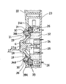
- elastic foam
- Prior art date
- Legal status (The legal status is an assumption and is not a legal conclusion. Google has not performed a legal analysis and makes no representation as to the accuracy of the status listed.)
- Expired - Fee Related
Links
- 238000005286 illumination Methods 0.000 title claims description 28
- 230000002265 prevention Effects 0.000 title claims description 9
- 239000006260 foam Substances 0.000 claims description 27
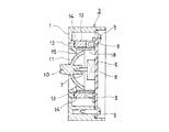
- 230000002093 peripheral effect Effects 0.000 description 6
- 239000004925 Acrylic resin Substances 0.000 description 3
- 229920000178 Acrylic resin Polymers 0.000 description 3
- 239000000463 material Substances 0.000 description 2
- 239000011347 resin Substances 0.000 description 2
- 229920005989 resin Polymers 0.000 description 2
- 239000000853 adhesive Substances 0.000 description 1
- 230000001070 adhesive effect Effects 0.000 description 1
- 239000002390 adhesive tape Substances 0.000 description 1
- 230000000694 effects Effects 0.000 description 1
- 230000005489 elastic deformation Effects 0.000 description 1
- 230000002708 enhancing effect Effects 0.000 description 1
- HQQADJVZYDDRJT-UHFFFAOYSA-N ethene;prop-1-ene Chemical group C=C.CC=C HQQADJVZYDDRJT-UHFFFAOYSA-N 0.000 description 1
- 238000001746 injection moulding Methods 0.000 description 1
- 238000000465 moulding Methods 0.000 description 1
- 230000000630 rising effect Effects 0.000 description 1
- 239000000779 smoke Substances 0.000 description 1
Images



Classifications
-
- H—ELECTRICITY
- H01—ELECTRIC ELEMENTS
- H01H—ELECTRIC SWITCHES; RELAYS; SELECTORS; EMERGENCY PROTECTIVE DEVICES
- H01H2219/00—Legends
- H01H2219/054—Optical elements
- H01H2219/062—Light conductor
- H01H2219/0622—Light conductor only an illuminated ring around keys
Landscapes
- Switches With Compound Operations (AREA)
- Switch Cases, Indication, And Locking (AREA)
- Push-Button Switches (AREA)
Description
【0001】
【発明の属する技術分野】
本発明は、例えば自動車に設備される操作スイッチの周辺部を発光表示させる発光表示部を設けてなるスイッチの照明光漏れ防止構造であって、特にその照明光の漏れ防止構造を簡素化して経済性を高めると共に、その操作スイッチ周辺部からの漏光を有効に防止させることができる構造となしたスイッチ照明光の光漏れ防止構造に関する。
【0002】
【従来の技術】
図3は、自動車の運転席前方に設備されるマルチディスプレイ装置(車両情報表示器)であって、このマルチディスプレイ装置のハウジング1の起立面中央部には表示器2が、その右側部にはジョイスティック型スイッチ構造体3が設けられており、またハウジング1の水平面には、各操作スイッチの操作ノブ4が配列されている。
【0003】
上記ジョイスティック型スイッチ構造体3の内部構成は図4、図5で示すように、ハウジング1の裏側からそのハウジング1に対して取付ねじ5によって取付けられるプリント基板6を有し、このプリント基板6には上下左右及び前後方向の三次元方向へ操作し得る操作軸7を有するジョイスティック型スイッチ本体8と、後述する照明部を透過照明するための複数の光源9が配設支持されている。ジョイスティック型スイッチ本体8の内部構成は周知構造であるので、そのスイッチ本体8の内部構成についての説明は省略する。
【0004】
10は上記操作軸7に取付けられる断面略半球形状のスカート部11を有するスイッチ操作ノブであり、このスイッチ操作ノブ10及びジョイスティック型スイッチ本体8の周囲には、上記光源9からの光を受光する受光面12Aを有する環状のライトガイド12が位置される。このライトガイド12の端面(発光面12B)には、発光照明部13を有する環状の照明レンズ14が当接されるものであり、その照明レンズ14はハウジング1に設けられているスイッチ操作孔15の周囲に形成されている照明レンズ嵌合部16内に嵌入されて、上記の各発光照明部13は、ハウジング1に設けられている照明レンズ嵌合部16に穿設されている各表示孔17から透視される構成となっている。さらに上記ライトガイド12の内周面及びランプ9の内側には環状の遮光部材18が嵌合されていてスイッチ操作孔15からの漏光が防止されるように構成されている。
【0005】
このような構成の従来のジョイスティック型スイッチ構造体3にあっては、スイッチ操作孔15の周辺部にスイッチ操作ノブ10の操作方向を表示するための表示孔17を設け、ランプ9を点灯したとき、該光源9から発する光を、ライトガイド12及び照明レンズ14を介して、発光照明部13で発光表示させることができる。また上記光源9及びライトガイド12の内側に位置される遮光部材18により、そのランプ及びライトガイド12の光がスイッチ操作孔15から漏れることがなく、これにより表示品質が高められるように構成されている。
【0006】
【発明が解決しようとする課題】
ところが、このような従来のジョイスティック型スイッチ構造体にあっては、光源9の点灯時において、そのランプ光のそのスイッチ操作孔15からの漏れ防止するための手段として、インジェクション成形により環状に樹脂成形された高価な遮光部材18をスイッチ操作部ノブ10と光源9及びライトガイド12との間に配置しなければならず、これが原因で発光照明部を有するジョイスティック型スイッチが高価となり経済性に欠けるものであった。また従来のジョイスティック型スイッチ3にあっては、別部材に形成されているライトガイド12、照明レンズ14及び遮光部材18のそれぞれの部材を組合せ使用していることから、使用部品点数が嵩みこれが原因で組立作業性及び生産性が悪くなるという問題点もあった。
【0007】
本発明はかかる従来の問題点に着目してなされたもので、スイッチ操作孔からの漏光を防止するために使用する遮光部材を、安価にしてしかもスイッチ構造の組付作業性にも優れる弾性発泡体を使用するようにして、照明手段を有するスイッチ装置における光漏れ構造の経済性を高めることを第1の目的とする。
【0008】
また、本発明では、スイッチ周辺を発光表示させるための発光表示機構を構成する構成部品点数を削減して漏光防止構造を具備するスイッチ構造の組立作業性を高めることを第2の目的とする。
【0009】
【課題を解決するための手段】
上記第1および第2の目的を達成するための発明は、請求項1に記載した、ハウジングケースの底面に配設されるプリント基板に実装されたスイッチ本体と、断面略半球状のスカート部と摘み部とを有し、その摘み部を前記ハウジングケースのスイッチ操作孔から外部に突出させたスイッチ操作ノブと、該スイッチ操作ノブのスカート部の外表面と所定の間隔を保持した内表面を有し、かつ一端面を前記スイッチ操作孔の周辺を発光表示する発光面とし他端面を受光面とした環状のガイドライトと、該環状のガイドライトの受光面に近接して配設された光源と、からなるジョイスティック型スイッチにおいて、前記スイッチ操作ノブのスカート部の外表面と前記環状のライトガイドの内表面との間の隙間を遮蔽する環状の遮光弾性発泡体を、前記スイッチ本体を取り囲むように該遮光弾性発泡体が保有する弾性復元力でその遮光弾性発泡体の一端面を前記プリント基板に、他端面を前記スイッチ操作ノブのスカート部辺縁及び前記ライトガイドへ弾圧的に圧接保持せしめて、該隙間を通ってスイッチ構造体外部へ出射する前記光源からの直射光の漏れを防止することを特徴とするスイッチ照明光の光漏れ防止構造である。
【0011】
【発明の実施の形態】
以下に本発明を図1に示す第1の実施形態に基いて詳細に説明する。
【0012】
図1に示すジョイスティック型スイッチ構造体21は、例えば従来例で示した車両情報表示器に設備されるものであって、このジョイスティック型スイッチ構造体21の内部構成は、ハウジングケース22の裏側から、そのハウジングケース22に対して取付けられるプリント基板23を有し、このプリント基板23には、上下左右及び前後方向の三次元方向へ操作し得る操作軸24を有する従来例で述べたと同様の構成であるジョイスティック型スイッチ本体25とそのジョイステック型スイッチ本体25の周辺部に配置される複数の光源26が配設支持されている。
【0013】
27は上記操作軸24に取付けられる断面略半球状のスカート部28を有するスイッチ操作ノブであり、このスイッチ操作ノブ27の外周、つまりスカート部28の外側面との対向位置には、透明又は半透明であるアクリル樹脂で形成された環状のライトガイド31が配置されている。このライトガイド31は、上記光源26からの光を受光する受光面31Aと、上記ハウジングケース22に形成されているスイッチ操作孔29の周囲4個所に形成されている発光表示孔30内に嵌入される発光面31Bを有している。
【0014】
32は上記プリント基板23と、スイッチ操作ノブ27のスカート部28周縁との間に介在されている環状(ドーナツ形状)の遮光弾性発泡体であって、この遮光弾性発泡体32の内側に上記ジョイスティック型スイッチ本体25が配置されており、また遮光弾性発泡体32の外側に上記光源26が配置されている。さらに該遮光弾性発泡体32は、上記スイッチ操作ノブ27のスカート部28外周面と、上記スイッチ操作孔29及びライトガイド31の内周面との間に生じる隙間(a)を塞ぐようにしてライトガイド31の内周面に対しても弾圧的に圧接されている。
【0015】
この遮光弾性発泡体32の材質は、耐熱性、耐候性等に優れたエチレン・プロピレン系によるスポンジ状のものであって、例えば日東電工(株)の製品である濃色又は黒色系のエプトシーラー(商品名)No. 685の使用が望ましいが、この材質に限られるものではなく、適宜可撓弾性を有する樹脂発泡体(スポンジ状のもの)を選んで使用することができる。またその遮光弾性発泡体32の大きさは、ジョイスティック型スイッチ構造体21の形状、大きさに対応して決めることができ、またその材質は、使用環境等に応じて選択使用することができる。
【0016】
上記遮光弾性発泡体32をジョイスティック型スイッチ構造体21内部に組付けるには、その遮光弾性発泡体32とプリント基板23の接合面を、例えば貼着テープ又は接着剤等を用いて接着し、また上記ジョイスティック型スイッチ構造体21の組付け完了時において、上記遮光弾性発泡体32が、スイッチ操作ノブのスカート部28辺縁と、プリント基板23との間で、遮光弾性発泡体32が保有する最大弾性変形量に対し、約20%程度に圧縮変形させた密着(密接)状態で、上記隙間(a)が遮光弾性発泡体32により完全に遮蔽され、これにより光源26からの光が隙間(a)を透してケース22外へ漏れることがないように設定している。
【0017】
以上が第1の本実施形態であるが、次にその作用について述べると、光源26が点灯されることにより、この光源26による発光は、ライトガイド31の受光面31Aで受光し、このライトガイド31の4個所の発光面31Bで発光表示される。このとき光源26による発光は、直射光も、ハウジングケース22及びプリント基板による反射光も、遮光弾性発泡体32による遮蔽作用により、該隙間(a)を透してケース22外へ漏れることはないので、遮光性のよいジョイスティック型スイッチ構造体となっている。
【0018】
また上記ライトガイド31は、光源26の受光面31Aと、ケース22の外面で発光表示される発光面31Bを有する一体構造であって、つまり従来例で説明したライトガイドと照明レンズとの2部材を兼用させた一体構造となしているので、ジョイスティック型スイッチ構造体の組立使用部品点数を削減することができる。
【0019】
さらにジョイスティック型スイッチ本体25は、遮光弾性発泡体32及びスイッチ操作ノブ27により包囲されているので、ジョイスティック型スイッチ本体25のスイッチ動作時に生じる動作音等がハウジングケース22の外部へ放出されにくく、静粛性にも優れるスイッチを提供することが可能となる。
【0020】
図2は本発明の第2の実施形態であって、この第2の実施形態では、環状に形成されているライトガイド33の構成が受光面31A及び発光面31Bを有するライトガイド本体31と、そのライトガイドの発光面31Bに当接される受光面34A及び上記ハウジングケース22に形成されているスイッチ操作孔29の周囲4個所に形成されている発光表示孔30内に嵌入される発光面34Bを有する照明レンズ34との組合せで成っている。
【0021】
そして、スイッチ操作ノブ27のスカート部28の外周面とスイッチ操作孔29及びライトガイド33との間に形成される隙間を塞ぐようにして、上記実施形態と同様に遮光弾性発泡体32が弾圧的に接触されている。その他の構成は第1の実施形態と同様である。
【0022】
このようにライトガイド33を、ライトガイド本体31と照明レンズ34とで構成することにより、例えばライトガイド本体31を透明なるアクリル樹脂で形成して導光効率を高めることができるようにし、また照明レンズ34を青、緑、橙等に有色し、又はスモーク調となしたアクリル樹脂で形成することにより、輝度を著しく低下させることなく着色表示させることができる。
【0023】
【発明の効果】
以上のように本発明のジョイスティック型スイッチ構造体によれば、そのプリント基板と、スイッチ操作ノブとの間に密着状態で介在せしめた環状の遮光弾性発泡体により、そのスイッチ構造体外部への光漏れを有効に防止することができるので、遮光構造の経済性が大幅に改善される。またライトガイドを照明レンズと兼ねる一体構造となしたので、使用部品点数が削減され、これによってもジョイスティック型スイッチ構造体の組付作業性及び経済性が高められる。
【0024】
さらにスイッチ操作ノブのスカート部周辺は、常に遮光弾性発泡体に圧接されているので、上記スイッチ操作ノブを例えば弾いたときに、その衝撃力が遮光弾性発泡体により吸収され、またジョイスティック型スイッチ本体は環状の遮光弾性発泡体で包囲されている等のことで静粛性にも優れたジョイスティック型スイッチ構造体が得られる。
【図面の簡単な説明】
【図1】本発明よりなるスイッチ照明光漏れ防止構造の第1の実施形態を示した断面図。
【図2】本発明よりなるスイッチ照明光漏れ防止構造の第2の実施形態を示した断面図。
【図3】スイッチ照明機構を具備するジョイスティック型スイッチを設けた車両情報表示器の斜視図。
【図4】従来のスイッチ照明機構を具備するジョイスティック型スイッチの分解斜視図。
【図5】従来のスイッチ照明機構を具備するジョイスティック型スイッチの断面説明図。
【符号の説明】
21…ジョイスティック型スイッチ構造体
22…ハウジングケース
23…プリント基板
24…操作軸
25…ジョイスティック型スイッチ本体
26…光源
27…スイッチ操作ノブ
27A…摘み部
28…スカート部
29…スイッチ操作孔
30…発光表示孔
31…ライトガイド(ライトガイド本体)
32…遮光弾性発泡体
33…ライトガイド
34…照明レンズ
a…隙間 [0001]
BACKGROUND OF THE INVENTION
The present invention relates to an illumination light leakage prevention structure for a switch provided with a light emitting display portion for emitting and displaying a peripheral portion of an operation switch installed in an automobile, for example, and in particular, the illumination light leakage prevention structure is simplified and economical. The present invention relates to a light leakage prevention structure for switch illumination light, which has a structure capable of enhancing the performance and effectively preventing light leakage from the periphery of the operation switch.
[0002]
[Prior art]
FIG. 3 shows a multi-display device (vehicle information display device) installed in front of the driver's seat of an automobile. The multi-display device has a
[0003]
As shown in FIGS. 4 and 5, the internal configuration of the joystick-
[0004]
[0005]
In the conventional joystick-
[0006]
[Problems to be solved by the invention]
However, in such a conventional joystick type switch structure, as a means for preventing leakage of the lamp light from the
[0007]
The present invention has been made by paying attention to such a conventional problem, and a light-shielding member used for preventing light leakage from the switch operation hole is an elastic foam which is inexpensive and excellent in assembling workability of the switch structure. The first object is to improve the economics of the light leakage structure in the switch device having the illumination means by using the body.
[0008]
A second object of the present invention is to improve the assembly workability of a switch structure having a light leakage prevention structure by reducing the number of components constituting a light emitting display mechanism for displaying light around the switch.
[0009]
[Means for Solving the Problems]
The invention for achieving the first and second objects includes a switch body mounted on a printed circuit board disposed on a bottom surface of a housing case, a skirt portion having a substantially hemispherical cross section, and A switch operating knob that protrudes outward from the switch operating hole of the housing case, and an inner surface that maintains a predetermined distance from the outer surface of the skirt of the switch operating knob. And an annular guide light having one end surface as a light emitting surface for emitting and displaying the periphery of the switch operation hole and the other end surface as a light receiving surface, and a light source disposed in the vicinity of the light receiving surface of the annular guide light; In the joystick type switch comprising: an annular light-shielding elastic foam that shields a gap between the outer surface of the skirt portion of the switch operation knob and the inner surface of the annular light guide; An elastic restoring force possessed by the light-shielding elastic foam so as to surround the switch body is such that one end face of the light-shielding elastic foam is on the printed circuit board and the other end is on the skirt edge of the switch operation knob and the light guide. The switch illumination light leakage prevention structure is characterized in that the pressure illumination is held in an elastic manner to prevent leakage of direct light from the light source emitted to the outside of the switch structure through the gap.
[0011]
DETAILED DESCRIPTION OF THE INVENTION
The present invention will be described in detail below based on the first embodiment shown in FIG.
[0012]
A joystick
[0013]
[0014]
An annular (doughnut-shaped) light-blocking
[0015]
The light-shielding
[0016]
In order to assemble the light-shielding
[0017]
The above is the first embodiment. Next, the operation thereof will be described. When the
[0018]
The
[0019]
Furthermore, since the joystick
[0020]
FIG. 2 shows a second embodiment of the present invention. In the second embodiment, the
[0021]
Then, the light-blocking
[0022]
Thus, by configuring the
[0023]
【The invention's effect】
As described above, according to the joystick-type switch structure of the present invention, light is transmitted to the outside of the switch structure by the annular light-shielding elastic foam interposed in close contact between the printed circuit board and the switch operation knob. Since leakage can be effectively prevented, the economics of the light shielding structure is greatly improved. Also since no integral structure serving as a light guide and an illumination lens, is reduced using number of components, which assembling workability and economy of the joystick type switch structure is enhanced by.
[0024]
Further, since the switch operation knob skirt is always pressed against the light-blocking elastic foam, the impact force is absorbed by the light-blocking elastic foam when the switch operation knob is bounced, and the joystick-type switch body. Is surrounded by an annular light-shielding elastic foam, so that a joystick type switch structure excellent in quietness can be obtained.
[Brief description of the drawings]
FIG. 1 is a cross-sectional view showing a first embodiment of a switch illumination light leakage prevention structure according to the present invention.
FIG. 2 is a sectional view showing a second embodiment of a switch illumination light leakage prevention structure according to the present invention.
FIG. 3 is a perspective view of a vehicle information display device provided with a joystick switch having a switch illumination mechanism.
FIG. 4 is an exploded perspective view of a joystick switch having a conventional switch illumination mechanism.
FIG. 5 is a cross-sectional explanatory view of a joystick type switch having a conventional switch illumination mechanism.
[Explanation of symbols]
DESCRIPTION OF
27A ...
32 ... Light-shielding
a ... Gap
Claims (1)
断面略半球状のスカート部と摘み部とを有し、その摘み部を前記ハウジングケースのスイッチ操作孔から外部に突出させたスイッチ操作ノブと、
該スイッチ操作ノブのスカート部の外表面と所定の間隔を保持した内表面を有し、かつ一端面を前記スイッチ操作孔の周辺を発光表示する発光面とし他端面を受光面とした環状のガイドライトと、
該環状のガイドライトの受光面に近接して配設された光源と、
からなるジョイスティック型スイッチにおいて、
前記スイッチ操作ノブのスカート部の外表面と前記環状のライトガイドの内表面との間の隙間を遮蔽する環状の遮光弾性発泡体を、前記スイッチ本体を取り囲むように該遮光弾性発泡体が保有する弾性復元力でその遮光弾性発泡体の一端面を前記プリント基板に、他端面を前記スイッチ操作ノブのスカート部辺縁及び前記ライトガイドへ弾圧的に圧接保持せしめて、該隙間を通ってスイッチ構造体外部へ出射する前記光源からの直射光の漏れを防止することを特徴とするスイッチ照明光の光漏れ防止構造。A switch body mounted on a printed circuit board disposed on the bottom surface of the housing case;
A switch operation knob having a skirt portion having a substantially hemispherical cross section and a knob, the knob protruding outward from the switch operation hole of the housing case;
An annular guide having an inner surface maintaining a predetermined distance from the outer surface of the skirt portion of the switch operation knob, and having one end surface as a light emitting surface for emitting and displaying the periphery of the switch operation hole and the other end surface as a light receiving surface. With lights,
A light source disposed in the vicinity of the light receiving surface of the annular guide light;
In the joystick type switch consisting of
The light-shielding elastic foam has an annular light-shielding elastic foam that shields the gap between the outer surface of the skirt portion of the switch operating knob and the inner surface of the annular light guide so as to surround the switch body. One end face of the light-blocking elastic foam is elastically restored to the printed circuit board and the other end face is held in pressure contact with the edge of the skirt portion of the switch operation knob and the light guide, and the switch structure passes through the gap. A light leakage prevention structure for switch illumination light, wherein leakage of direct light from the light source emitted to the outside of the body is prevented.
Priority Applications (1)
| Application Number | Priority Date | Filing Date | Title |
|---|---|---|---|
| JP28004098A JP3670141B2 (en) | 1998-10-01 | 1998-10-01 | Light leakage prevention structure for switch illumination light |
Applications Claiming Priority (1)
| Application Number | Priority Date | Filing Date | Title |
|---|---|---|---|
| JP28004098A JP3670141B2 (en) | 1998-10-01 | 1998-10-01 | Light leakage prevention structure for switch illumination light |
Publications (2)
| Publication Number | Publication Date |
|---|---|
| JP2000113760A JP2000113760A (en) | 2000-04-21 |
| JP3670141B2 true JP3670141B2 (en) | 2005-07-13 |
Family
ID=17619470
Family Applications (1)
| Application Number | Title | Priority Date | Filing Date |
|---|---|---|---|
| JP28004098A Expired - Fee Related JP3670141B2 (en) | 1998-10-01 | 1998-10-01 | Light leakage prevention structure for switch illumination light |
Country Status (1)
| Country | Link |
|---|---|
| JP (1) | JP3670141B2 (en) |
Families Citing this family (4)
| Publication number | Priority date | Publication date | Assignee | Title |
|---|---|---|---|---|
| DE20221846U1 (en) | 2002-07-26 | 2008-07-17 | Dorma Gmbh + Co. Kg | Safety and monitoring device for doors, windows or the like |
| JP4708220B2 (en) * | 2006-03-03 | 2011-06-22 | 富士通株式会社 | Illumination device and imaging device using the same |
| JP4725384B2 (en) * | 2006-03-24 | 2011-07-13 | サクサ株式会社 | Pushbutton switch lighting structure |
| CN108392188B (en) * | 2018-05-15 | 2024-01-16 | 苏州国科盈睿医疗科技有限公司 | An easy-to-install mobile phone dermatoscope |
-
1998
- 1998-10-01 JP JP28004098A patent/JP3670141B2/en not_active Expired - Fee Related
Also Published As
| Publication number | Publication date |
|---|---|
| JP2000113760A (en) | 2000-04-21 |
Similar Documents
| Publication | Publication Date | Title |
|---|---|---|
| JP4596100B2 (en) | Lighting device | |
| CN116547189B (en) | Heat dissipation of the steering wheel light bar assembly | |
| JPH09115376A (en) | Control device for vehicle air conditioner | |
| JP5292964B2 (en) | Translucent operation unit | |
| TWI422305B (en) | Electrical device | |
| JP2000113760A (en) | Light leakage prevention structure for switch illumination light | |
| JP2001155573A (en) | switch | |
| JP2019200937A (en) | Vehicle lamp fitting | |
| JP6162163B2 (en) | Assembly structure for analog watches for vehicles | |
| CN222775193U (en) | Key structure and electronic equipment | |
| JPH066394Y2 (en) | Built-in structure of display board | |
| CN221718492U (en) | Luminous grille and vehicle | |
| JP4889547B2 (en) | Operation switch | |
| JP3128431B2 (en) | Operation device | |
| JP5325279B2 (en) | Exterior parts for vehicles | |
| TWI923398B (en) | Light guiding module and electronic device | |
| JP2002110003A (en) | Switch device | |
| CN218447136U (en) | Display device and intelligent toilet bowl with same | |
| JP2004180068A (en) | Mobile terminal | |
| JP7070027B2 (en) | Display device | |
| JP2020190512A (en) | Panel instrument | |
| CN211294927U (en) | Button assembly and monitoring patch | |
| CN111603025B (en) | Cooking utensil | |
| JPH11111097A (en) | Push button switch device | |
| JP2004031113A (en) | Dome switch |
Legal Events
| Date | Code | Title | Description |
|---|---|---|---|
| A977 | Report on retrieval |
Free format text: JAPANESE INTERMEDIATE CODE: A971007 Effective date: 20040609 |
|
| A131 | Notification of reasons for refusal |
Free format text: JAPANESE INTERMEDIATE CODE: A131 Effective date: 20040615 |
|
| A521 | Written amendment |
Free format text: JAPANESE INTERMEDIATE CODE: A523 Effective date: 20040805 |
|
| A131 | Notification of reasons for refusal |
Free format text: JAPANESE INTERMEDIATE CODE: A131 Effective date: 20050208 |
|
| A521 | Written amendment |
Free format text: JAPANESE INTERMEDIATE CODE: A523 Effective date: 20050216 |
|
| TRDD | Decision of grant or rejection written | ||
| A01 | Written decision to grant a patent or to grant a registration (utility model) |
Free format text: JAPANESE INTERMEDIATE CODE: A01 Effective date: 20050322 |
|
| A61 | First payment of annual fees (during grant procedure) |
Free format text: JAPANESE INTERMEDIATE CODE: A61 Effective date: 20050413 |
|
| R150 | Certificate of patent or registration of utility model |
Free format text: JAPANESE INTERMEDIATE CODE: R150 |
|
| FPAY | Renewal fee payment (event date is renewal date of database) |
Free format text: PAYMENT UNTIL: 20090422 Year of fee payment: 4 |
|
| S531 | Written request for registration of change of domicile |
Free format text: JAPANESE INTERMEDIATE CODE: R313531 |
|
| FPAY | Renewal fee payment (event date is renewal date of database) |
Free format text: PAYMENT UNTIL: 20090422 Year of fee payment: 4 |
|
| R350 | Written notification of registration of transfer |
Free format text: JAPANESE INTERMEDIATE CODE: R350 |
|
| FPAY | Renewal fee payment (event date is renewal date of database) |
Free format text: PAYMENT UNTIL: 20100422 Year of fee payment: 5 |
|
| LAPS | Cancellation because of no payment of annual fees |