JP3670366B2 - Chemical analyzer - Google Patents
Chemical analyzer Download PDFInfo
- Publication number
- JP3670366B2 JP3670366B2 JP28863095A JP28863095A JP3670366B2 JP 3670366 B2 JP3670366 B2 JP 3670366B2 JP 28863095 A JP28863095 A JP 28863095A JP 28863095 A JP28863095 A JP 28863095A JP 3670366 B2 JP3670366 B2 JP 3670366B2
- Authority
- JP
- Japan
- Prior art keywords
- cuvette
- conveyor
- sensor
- analyzer
- arm
- Prior art date
- Legal status (The legal status is an assumption and is not a legal conclusion. Google has not performed a legal analysis and makes no representation as to the accuracy of the status listed.)
- Expired - Fee Related
Links
- 239000000126 substance Substances 0.000 title claims description 10
- 238000001514 detection method Methods 0.000 claims description 6
- 238000004458 analytical method Methods 0.000 claims description 5
- 238000000034 method Methods 0.000 abstract description 6
- 238000003556 assay Methods 0.000 description 6
- 230000001580 bacterial effect Effects 0.000 description 4
- 239000003153 chemical reaction reagent Substances 0.000 description 4
- 230000005670 electromagnetic radiation Effects 0.000 description 3
- 238000003018 immunoassay Methods 0.000 description 2
- 230000032258 transport Effects 0.000 description 2
- 241000894006 Bacteria Species 0.000 description 1
- 230000000694 effects Effects 0.000 description 1
- 230000003287 optical effect Effects 0.000 description 1
- 230000005855 radiation Effects 0.000 description 1
- 239000000758 substrate Substances 0.000 description 1
- 238000005406 washing Methods 0.000 description 1
Images




Classifications
-
- G—PHYSICS
- G01—MEASURING; TESTING
- G01N—INVESTIGATING OR ANALYSING MATERIALS BY DETERMINING THEIR CHEMICAL OR PHYSICAL PROPERTIES
- G01N35/00—Automatic analysis not limited to methods or materials provided for in any single one of groups G01N1/00 - G01N33/00; Handling materials therefor
- G01N35/02—Automatic analysis not limited to methods or materials provided for in any single one of groups G01N1/00 - G01N33/00; Handling materials therefor using a plurality of sample containers moved by a conveyor system past one or more treatment or analysis stations
-
- G—PHYSICS
- G01—MEASURING; TESTING
- G01N—INVESTIGATING OR ANALYSING MATERIALS BY DETERMINING THEIR CHEMICAL OR PHYSICAL PROPERTIES
- G01N35/00—Automatic analysis not limited to methods or materials provided for in any single one of groups G01N1/00 - G01N33/00; Handling materials therefor
- G01N35/02—Automatic analysis not limited to methods or materials provided for in any single one of groups G01N1/00 - G01N33/00; Handling materials therefor using a plurality of sample containers moved by a conveyor system past one or more treatment or analysis stations
- G01N35/04—Details of the conveyor system
-
- G—PHYSICS
- G01—MEASURING; TESTING
- G01N—INVESTIGATING OR ANALYSING MATERIALS BY DETERMINING THEIR CHEMICAL OR PHYSICAL PROPERTIES
- G01N35/00—Automatic analysis not limited to methods or materials provided for in any single one of groups G01N1/00 - G01N33/00; Handling materials therefor
- G01N35/02—Automatic analysis not limited to methods or materials provided for in any single one of groups G01N1/00 - G01N33/00; Handling materials therefor using a plurality of sample containers moved by a conveyor system past one or more treatment or analysis stations
- G01N35/04—Details of the conveyor system
- G01N2035/0401—Sample carriers, cuvettes or reaction vessels
- G01N2035/0427—Sample carriers, cuvettes or reaction vessels nestable or stockable
-
- Y—GENERAL TAGGING OF NEW TECHNOLOGICAL DEVELOPMENTS; GENERAL TAGGING OF CROSS-SECTIONAL TECHNOLOGIES SPANNING OVER SEVERAL SECTIONS OF THE IPC; TECHNICAL SUBJECTS COVERED BY FORMER USPC CROSS-REFERENCE ART COLLECTIONS [XRACs] AND DIGESTS
- Y10—TECHNICAL SUBJECTS COVERED BY FORMER USPC
- Y10T—TECHNICAL SUBJECTS COVERED BY FORMER US CLASSIFICATION
- Y10T436/00—Chemistry: analytical and immunological testing
- Y10T436/11—Automated chemical analysis
- Y10T436/113332—Automated chemical analysis with conveyance of sample along a test line in a container or rack
- Y10T436/114165—Automated chemical analysis with conveyance of sample along a test line in a container or rack with step of insertion or removal from test line
Landscapes
- General Health & Medical Sciences (AREA)
- Health & Medical Sciences (AREA)
- Life Sciences & Earth Sciences (AREA)
- Chemical & Material Sciences (AREA)
- Analytical Chemistry (AREA)
- Biochemistry (AREA)
- Physics & Mathematics (AREA)
- General Physics & Mathematics (AREA)
- Immunology (AREA)
- Pathology (AREA)
- Automatic Analysis And Handling Materials Therefor (AREA)
- Optical Measuring Cells (AREA)
- Attitude Control For Articles On Conveyors (AREA)
Abstract
Description
【0001】
【発明の属する技術分野】
本発明は、供給源から細菌培養器へのキュベットのコンベアに関し、詳細には1つより多いキュベットが供給源から細菌培養器へと送られているかどうかを検知することのできるキュベットの運搬装置に関する。
【0002】
【従来の技術】
カップ形状のキュベットを、例えば米国特許第5,271,896号(第4図から第8図)と米国特許第5,244,633号に示されるように、供給源、例えば積層体からある種のコンベア上に落下させることが知られている。しかし、これが行われている時1つのキュベットだけが1度に分配されることが重要である。
【0003】
【発明が解決しようとする課題】
本発明以前には、コンベアの1つの部署に1つより多いキュベットが配置されていることを詳細に知らせる装置が必要とされていた。
【0004】
【課題を解決するための手段】
上記の要求を満たす装置が提供される。
【0005】
さらに、詳細には、本発明の1つの形態によれば、選択された反応キュベットを分析装置のキュベット分配部署から分配されたキュベットのための処理部署に運ぶコンベアを具備する化学分析装置が提供され、前記コンベアは、キュベットをコンベア上に保持しまたキュベットをコンベアから解放する手段を含んでいる。分析装置は、これがさらに、コンベア上に分配されたキュベットの数が1つより多いかどうかを、選択されたキュベットの頂端より上に突出するキュベットが存在するか存在しないかを検知することによって、検出するセンサーを含んでいる点において改良されている。
【0006】
本発明の他の形態によれば、分配されたキュベットの数が零であるかどうかをコンベアの頂部の上方を通過したエネルギーのビームを邪魔しないことを検知することにより検出するセンサーを改良した分析装置が提供される。
【0007】
本発明の他の形態によればキュベット内の湿式検定のため分析装置の反応キュベットを提供する方法が提供され、この方法は、
(a)分析装置の内部に反応キュベットの供給源を設ける段階と、
(b)キュベットを前記供給源から取出しコンベア上に移動させる段階と、
(c)取出されたキュベットをコンベアを動かすことにより分析装置の他の部分に運ぶ段階と、
(d)前記段階(c)に関連して、1つのキュベットのみが前記段階(b)によりコンベア上に移動されたかどうかを検出する段階
とを含んでいる。
【0008】
【発明の実施の形態】
本発明は、好適な型の反応キュベットを免疫学的検定のため好適な型の湿式検定分析装置で処理するよう運搬し、キュベットがコンベアから落下され光ビームにより検知される好適な実施態様について記載される。さらに、本発明は(a)用いられる反応キュベットの型、(b)用いられる湿式検定分析装置の型、(c)キュベットで行われる検定の型式、(d)キュベットがコンベアから解放されるかどうか、及び(e)検知のために用いられるエネルギービームの型に、それぞれ関係なく有用である。
【0009】
したがって、図1の好適なキュベットCは、好適な湿式検定分析装置10に加えて、米国特許第5,244,633号に記載されたキュベットであり、さらに詳細には普通に所有された、「試薬を除去することなく積重ね可能な試薬カップ形状」なる名称の米国特許第5,441,895号に記載されているキュベットである。すなわち、このようなキュベットはキュベットの内部の表面に取付けられた抗体を用いる湿式免疫学的検定のために提供される。前記米国特許第5,441,895号の詳細は参照例として本明細書に明瞭に記載されている。
【0010】
好ましくは、図1で、キュベットCは多くのキュベットを積層体14の形式で保持している供給源12から供給される。最も底側のキュベットは矢示18のように下方に押される適当なプランジャー16により積層体から分配され又は取出される。複数の積層体(図示しない)が普通に所有された「固定瓶保持装置」なる名称の米国特許第5,322,668号に示されているような試薬包装を介して供給することができる。例えば前記の米国特許第5,271,896号に教示されているような、プランジャー機構が有用である。
【0011】
キュベットC’が仮想矢印20に示すように積層体から落下し離れるとき、キュベットC’はさらに十分に後述されるように、本発明のコンベア50により受け止められる。このコンベアはキュベットを、軸線34の周りに回転されキュベットを処理部署36,38及び40を通って運ぶ細菌培養器リング32に移送する。部署36は例えば、患者標本が置かれる部署であり、部署38と40は試薬が必要なときに加えられる部署である。洗浄と読取りがさらに他の部署(図示しない)で行われ、この読取りは好ましくは光学的計量器で行われる。これらの他の部署のうちのある部署には好ましくは、前記米国特許第5,244,633号に記載されているような、図示しない第2の同心のリングにキュベットを移送することにより到達する。
【0012】
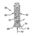
図2から4のコンベア50は好ましくは、固定された基体58の周りを図1の矢印56の方向に回動するよう一端54に回動自在に取付けられたアーム52を具備している。図示のように相互に接合された2つの部材を具備することのできる図2のアーム52はアーム52の一端54の近くでアーム52に端部64が取付けられた一対の弾性顎60,62を含んでいる。アーム52は図5の頂面65と開口67とを有している。これらの弾性顎は矢印66のように内側に向って押すようこの取付けにより付勢されている。したがって、弾性顎は平常時距離“d”だけ離間され、この距離“d”は積層体14から解放されたキュベットC''を端部64の反対側の顎の自由端68,70の間に受け取り保持するのに十分な距離となっている。さらに、図3を参照されたい。
【0013】
アーム52が図1でリング32の上方で仮想位置へと回動された時にキュベットC''を解放するため、カム部材74が設けられる。カム部材74は図4の矢印76のように適当な機構によって押され顎60と62の端部68,70の間を通過する。カム部材74の増大する傾斜は、端部68,70を図3の矢印80のように端部68,70を離間するよう拡げる作用をし、それによりキュベットC''を解放しキュベットC''は図1のリング32の開口84の中に矢印82のように落下する。拡げられ離間された端部を仮想線で示す図3をも参照されたい。
【0014】
本発明によれば、1つより多いキュベットがコンベア50上に分配され又は解放されたか否かを検知するため、センサー100が図示のようにコンベアの一部として又は仮想線で示される分析装置における別の部署として、図5のように設けられる。いずれの場合も、センサー100は電磁放射線の源110、例えば赤外線ビーム112を発するLED(発光ダイオード)と、少なくとも1つの鏡114と上記の電磁放射線のためのフォトダイオード115のような検知器とを具備している。一対の反射面、例えば鏡114,116が用いられ、それぞれが光ビームに対し45°の角度で、アーム52の回動端部54に取付けられた端部122から延びるアーム120の部分118と119にそれぞれ取付けられており、アーム120は124で上方に向って曲げられ第1の支持部(鏡116のための)を提供し、また126で下方に向って曲げられ第2の支持部(鏡114のための)を提供する。アームの開口127はキュベットCがアーム52を通って落下し顎60,62上に載ることができるようにする。(電磁線源110と検知器115は好ましくは、弾性顎60,62が解放した時矢印134のようにキュベットC''' が落下できる図示しない開口を有するアーム52に平行なアーム132上に支持される。)図示しない公知のマイクロプロセッサーが検知器115からの信号を読み取り処理するために用いられる。
【0015】
センサーの作用は好ましくは、図5で1つのキュベットC''' が又は他の数の、すなわち零もしくは1つより多い数のキュベットが受け取られたかどうかを検出する作用である。これは、その幅Wが実線で示される単一のキュベット又はキュベットC''' の頂部に積重ねられた第2の(又はさらに第3の)キュベットによって生じる1つより多いキュベットの両方に及ぶ、幅広のビーム112の、アーム52の頂面65を横切る投射により行われる。検知器115は次に、全ビームもしくはビームの一部を、又はビームの実質的にないのを検出する。これらの3つの条件はそれぞれ、キュベットが分配されない、1つだけ分配される、及び1つより多くが分配される、を表わす。受け取られた信号の強さはそれから公知のソフトウェアにより分析装置への“進行”又は“停止”の信号に変換され、ここで“進行”の信号はビームの一部が検出された時のみに生じる。
【0016】
“停止”信号が発せられたならば、この信号は検査され受けられたビームが十分に強いか又は本質的に零の強さであるかどうかを知るようにする。前者の場合は、他の1つのキュベットが分配される。後者の場合は、コンベア50上の1つより多いキュベットの許されない積層体が適当な部署で排除され、そしてアーム52が1つのキュベットだけが受け取られたのを検出するまでキュベットの分配段階を繰返すため戻される。
【0017】
このほかに(図示しないが)、ビーム112はその幅を狹くし、1つのキュベットだけが分配されたかもしくは分配されなかったこと(ビームは第1のキュベットによってのみ、邪魔されるように狹くなっている)又は1つの積層体(1つより多いキュベット)だけが分配されもしくは分配されなかったこと(この狹いビームが単一の分配され受け取られたキュベットの上方を通過する)を検出するようにすることができる。しかし、より良好な方法は幅広のビームWを用い3つの条件の全てを検出することであることが理解されるであろう。
【0018】
上記の実施態様において、センサー100がコンベア50と共に連続して動き、それにより1つより多いキュベットが所定位置にあるのを検知するのを、コンベアがキュベットを運んでいる間でも何時も行うことができるようにする。
【0019】
このほかに、仮想線で示すように、鏡114と116を取付けるアーム120の部分118,119の代わりに、部分118,119が適当な角度で取付けられる頂部バー202を有する固定された部署から延びる突起とすることができる。この場合は、アーム120と132が省略されそして代わりにエネルギー源110と検知器116が仮想線で示すように部署200の底部バー204上に取付けられる。そして検知は、コンベア50を回転させ途中で部署200を通過しキュベットをリング32に運ぶことにより、行われる。
【0020】
さらに他の方法は、2つの鏡の代わりに単一の鏡を用いることである。これは図6の実施態様において、行われ、鏡面がわん曲部分300によって相互に接合された2つの平坦部分114Aと116Aを有する単一の鏡である。この鏡の取付けは、鏡がコンベアにより担持されるか又は所定位置に固定されるかによって、仮想線で示すようになる。
【0021】
またさらに他の図7の実施態様においては、1つの平坦部分のみを有する単一の鏡が用いられる。さきに記載されたのと同様の部品は区別する“B”が添付された同一の参照番号が付けられている。したがって、コンベア50BがC''' のようなキュベットを受け取るためのアーム52Bを有し、またエネルギー源110Bが上記のように零、1つ、又は1つより多いキュベットを検出するよう検知器115Bと共に用いられる。しかし、鏡114Bがアーム120B上に取付けられ、そして他の実施態様で用いられた反射面116に代えて検知器115Bが取付けられている。
【0022】
【発明の効果】
本発明の有利な技術的特徴は、分析装置がたまたま1つより多いキュベットを1度にコンベア上に分配するのを自動的に検出しそして適当な処理をとることである。
【0023】
本発明の関連した有利の技術的特徴は、このような検知が、別の部署で検知を行うために停止することなく細菌培養器がキュベットの供給源から分析装置の載せ台へと動いている間に行われることである。
【図面の簡単な説明】
【図1】1つのキュベットをキュベットの積層源から離れるよう移送するコンベアと共に構成された分析装置の破截部分概略切断正面図である。
【図2】図1のII−II線に沿った断面図である。
【図3】図2のIII −III 線に沿った端面図である。
【図4】運搬されたキュベットの解放を示す図2と同様の断面図である。
【図5】本発明のセンサーと検知方法の破截正面図である。
【図6】他の実施態様における鏡を示す部分図である。
【図7】他の実施態様を示す図5と同様の破截正面図である。
【符号の説明】
C,C’,C'',C''' …キュベット
10…湿式検定分析装置
12…キュベット供給源
14…積層体
16…プランジャー
32…細菌培養器リング
36,38,40…処理部署
50…コンベア
52…アーム
54…アーム一端
58…基体
60,62…弾性顎
65…頂面
67…開口
68,70…顎自由端
74…カム部材
100…センサー
110…放射線源
112…赤外線ビーム
114,116…鏡
115…フォトダイオード
120…アーム
127…アーム開口
132…アーム[0001]
BACKGROUND OF THE INVENTION
The present invention relates to a cuvette conveyor from a source to a bacterial incubator, and in particular to a cuvette transport device capable of detecting whether more than one cuvette is being sent from the source to the bacterial incubator. .
[0002]
[Prior art]
Cup-shaped cuvettes are available from certain sources, such as laminates, as shown, for example, in US Pat. No. 5,271,896 (FIGS. 4-8) and US Pat. No. 5,244,633. It is known to drop onto a conveyor. However, it is important that only one cuvette is dispensed at a time when this is done.
[0003]
[Problems to be solved by the invention]
Prior to the present invention, there was a need for a device that informed in detail that more than one cuvette was placed in one section of the conveyor.
[0004]
[Means for Solving the Problems]
An apparatus is provided that meets the above requirements.
[0005]
More particularly, according to one aspect of the present invention, there is provided a chemical analyzer comprising a conveyor for transporting selected reaction cuvettes from a cuvette dispensing section of the analyzer to a processing section for dispensed cuvettes. The conveyor includes means for holding the cuvette on the conveyor and releasing the cuvette from the conveyor. The analyzer further detects whether there is more than one cuvette dispensed on the conveyor and whether there is a cuvette protruding above the top of the selected cuvette, Improved in that it includes a sensor to detect.
[0006]
According to another aspect of the invention, an improved analysis of a sensor that detects whether the number of dispensed cuvettes is zero by not disturbing the beam of energy that has passed above the top of the conveyor. An apparatus is provided.
[0007]
According to another aspect of the present invention, there is provided a method for providing an analytical device reaction cuvette for wet assay in a cuvette, the method comprising:
(A) providing a reaction cuvette source inside the analyzer;
(B) moving the cuvette from the supply source onto a conveyor;
(C) carrying the removed cuvettes to other parts of the analyzer by moving the conveyor;
(D) in connection with step (c), detecting whether only one cuvette has been moved onto the conveyor according to step (b).
[0008]
DETAILED DESCRIPTION OF THE INVENTION
The present invention describes a preferred embodiment in which a suitable type of reaction cuvette is transported for processing in a suitable type of wet assay analyzer for immunoassay and the cuvette is dropped from a conveyor and detected by a light beam. Is done. Further, the present invention includes (a) the type of reaction cuvette used, (b) the type of wet assay analyzer used, (c) the type of assay performed on the cuvette, and (d) whether the cuvette is released from the conveyor. And (e) useful regardless of the type of energy beam used for detection.
[0009]
Accordingly, the preferred cuvette C of FIG. 1 is the cuvette described in US Pat. No. 5,244,633 in addition to the preferred
[0010]
Preferably, in FIG. 1, the cuvette C is supplied from a
[0011]
When the cuvette C ′ falls off the stack as indicated by the virtual arrow 20, the cuvette C ′ is received by the
[0012]
The
[0013]
A
[0014]
In accordance with the present invention, the
[0015]
The sensor action is preferably the action of detecting whether one cuvette C ′ ″ in FIG. 5 or another number, ie zero or more than one cuvette, has been received. This covers both a single cuvette whose width W is indicated by a solid line or more than one cuvette produced by a second (or even third) cuvette stacked on top of a cuvette C ′ ″. This is done by projecting the
[0016]
If a “stop” signal is issued, this signal is examined to know if the received beam is sufficiently strong or essentially zero intensities. In the former case, one other cuvette is dispensed. In the latter case, the unacceptable stack of more than one cuvette on the
[0017]
In addition to this (not shown), the
[0018]
In the above embodiment, the
[0019]
In addition, instead of the
[0020]
Yet another method is to use a single mirror instead of two mirrors. This is done in the embodiment of FIG. 6 and is a single mirror having two
[0021]
In yet another embodiment of FIG. 7, a single mirror having only one flat portion is used. Parts similar to those described above are given the same reference number with a distinguishing "B" attached. Thus, conveyor 50B has an arm 52B for receiving a cuvette such as C ′ ″ and detector 115B so that
[0022]
【The invention's effect】
An advantageous technical feature of the present invention is that the analyzer automatically detects that more than one cuvette is dispensed on the conveyor at a time and takes appropriate action.
[0023]
A related advantageous technical feature of the present invention is that the bacteria incubator moves from the cuvette source to the analyzer platform without stopping such detection for detection in another department. Is to be done in between.
[Brief description of the drawings]
FIG. 1 is a schematic cut-away front view of a broken portion of an analyzer configured with a conveyor that transports one cuvette away from the cuvette stacking source.
FIG. 2 is a sectional view taken along line II-II in FIG.
3 is an end view taken along the line III-III in FIG.
4 is a cross-sectional view similar to FIG. 2, showing the release of the transported cuvette.
FIG. 5 is a broken front view of the sensor and detection method of the present invention.
FIG. 6 is a partial view showing a mirror in another embodiment.
FIG. 7 is a broken front view similar to FIG. 5 showing another embodiment.
[Explanation of symbols]
C, C ', C'',C''' ...
Claims (6)
Applications Claiming Priority (2)
| Application Number | Priority Date | Filing Date | Title |
|---|---|---|---|
| US335429 | 1994-11-07 | ||
| US08/335,429 US5567387A (en) | 1994-11-07 | 1994-11-07 | Cuvette conveyor and sensor |
Publications (2)
| Publication Number | Publication Date |
|---|---|
| JPH08219982A JPH08219982A (en) | 1996-08-30 |
| JP3670366B2 true JP3670366B2 (en) | 2005-07-13 |
Family
ID=23311736
Family Applications (1)
| Application Number | Title | Priority Date | Filing Date |
|---|---|---|---|
| JP28863095A Expired - Fee Related JP3670366B2 (en) | 1994-11-07 | 1995-11-07 | Chemical analyzer |
Country Status (7)
| Country | Link |
|---|---|
| US (1) | US5567387A (en) |
| EP (1) | EP0710840B1 (en) |
| JP (1) | JP3670366B2 (en) |
| AT (1) | ATE219250T1 (en) |
| AU (1) | AU3661995A (en) |
| CA (1) | CA2162239C (en) |
| DE (1) | DE69527022T2 (en) |
Families Citing this family (11)
| Publication number | Priority date | Publication date | Assignee | Title |
|---|---|---|---|---|
| EP1469178A3 (en) * | 1997-05-26 | 2005-06-08 | Nissan Motor Co., Ltd. | Engine idle speed controller |
| WO2003034076A1 (en) * | 2001-10-19 | 2003-04-24 | Monogen, Inc. | Article handling system and method |
| US20030087447A1 (en) | 2001-11-08 | 2003-05-08 | Blouin Matthew R | Sample well strip |
| USD481133S1 (en) | 2002-04-18 | 2003-10-21 | Instrumentation Laboratory Company | Sample well-strip for an automated sample analyzer |
| US8211386B2 (en) | 2004-06-08 | 2012-07-03 | Biokit, S.A. | Tapered cuvette and method of collecting magnetic particles |
| JP4365813B2 (en) * | 2004-09-22 | 2009-11-18 | オリンパス株式会社 | Stirring device, container and analyzer equipped with stirrer |
| US7731899B2 (en) | 2007-02-08 | 2010-06-08 | Biokit, S.A. | Apparatus and methods for dispensing sample holders |
| DE102010019232B4 (en) * | 2010-05-03 | 2013-06-27 | Eppendorf Ag | Avoid condensation hood |
| GB2513587A (en) | 2013-04-30 | 2014-11-05 | Stratec Biomedical Ag | Cuvette handling device |
| WO2019146220A1 (en) * | 2018-01-26 | 2019-08-01 | 株式会社日立ハイテクノロジーズ | Automated analyzer |
| LU103248B1 (en) * | 2024-02-19 | 2025-08-19 | Stratec Se | Container handling device |
Family Cites Families (13)
| Publication number | Priority date | Publication date | Assignee | Title |
|---|---|---|---|---|
| US3351177A (en) * | 1965-04-12 | 1967-11-07 | Ans Inc | Sample conveyor |
| US3532469A (en) * | 1966-10-29 | 1970-10-06 | Guido Vicario | System and equipment for the automation of chemical analysis |
| US3645690A (en) * | 1968-01-22 | 1972-02-29 | Beckman Instruments Inc | Automated chemical analyzer |
| US4099920A (en) * | 1977-03-17 | 1978-07-11 | Baxter Travenol Laboratories, Inc. | Temperature control and stirring apparatus for luminescence measuring photometer |
| US4260581A (en) * | 1979-02-07 | 1981-04-07 | Olympus Optical Co., Ltd. | Automatic analysis apparatus |
| DE4023149A1 (en) * | 1990-07-20 | 1992-01-23 | Kodak Ag | DEVICE FOR SCANING CONTAINERS WITH A LIQUID |
| US5266272A (en) * | 1991-10-31 | 1993-11-30 | Baxter Diagnostics Inc. | Specimen processing and analyzing systems with a station for holding specimen trays during processing |
| US5244633A (en) * | 1992-05-22 | 1993-09-14 | Eastman Kodak Company | Analyzer incubator with plural independently driven rings supporting cuvettes |
| US5332549A (en) * | 1992-07-01 | 1994-07-26 | Pb Diagnostic Systems, Inc. | Assay module transport apparatus for use in an automated analytical instrument |
| US5314825A (en) * | 1992-07-16 | 1994-05-24 | Schiapparelli Biosystems, Inc. | Chemical analyzer |
| US5271896A (en) * | 1993-04-16 | 1993-12-21 | Eastman Kodak Company | Plunger and driver mechanism for an analyzer |
| US5322668A (en) | 1993-07-01 | 1994-06-21 | Eastman Kodak Company | Locked bottle holder |
| US5441895A (en) | 1993-12-07 | 1995-08-15 | Jakubowicz; Raymond F. | Reagent cup shape allowing stacking without dislodging reagent |
-
1994
- 1994-11-07 US US08/335,429 patent/US5567387A/en not_active Expired - Lifetime
-
1995
- 1995-11-02 AU AU36619/95A patent/AU3661995A/en not_active Abandoned
- 1995-11-06 AT AT95307894T patent/ATE219250T1/en not_active IP Right Cessation
- 1995-11-06 EP EP95307894A patent/EP0710840B1/en not_active Expired - Lifetime
- 1995-11-06 CA CA002162239A patent/CA2162239C/en not_active Expired - Fee Related
- 1995-11-06 DE DE69527022T patent/DE69527022T2/en not_active Expired - Fee Related
- 1995-11-07 JP JP28863095A patent/JP3670366B2/en not_active Expired - Fee Related
Also Published As
| Publication number | Publication date |
|---|---|
| AU3661995A (en) | 1996-05-23 |
| JPH08219982A (en) | 1996-08-30 |
| EP0710840A1 (en) | 1996-05-08 |
| ATE219250T1 (en) | 2002-06-15 |
| DE69527022T2 (en) | 2003-01-02 |
| CA2162239A1 (en) | 1996-05-08 |
| US5567387A (en) | 1996-10-22 |
| DE69527022D1 (en) | 2002-07-18 |
| CA2162239C (en) | 2006-07-18 |
| EP0710840B1 (en) | 2002-06-12 |
Similar Documents
| Publication | Publication Date | Title |
|---|---|---|
| JP3931110B2 (en) | Automatic analyzer | |
| EP1109022B1 (en) | Cup handling subsystem for an automated clinical chemistry analyzer system | |
| JP5576889B2 (en) | Reagent and sample processing equipment for automated test systems | |
| JP6336715B2 (en) | Grip mechanism | |
| US5567387A (en) | Cuvette conveyor and sensor | |
| JPH06501311A (en) | Assay or reaction device | |
| US5422075A (en) | Chemical luminescence-detecting apparatus with multiple sensors | |
| JP6549960B2 (en) | Container supply unit and automatic analyzer | |
| JPH048741B2 (en) | ||
| CA1069340A (en) | Loading and unloading mechanism for continuously rotating container | |
| JP2000102769A (en) | Conveyor device for assorting agricultural product | |
| US5073916A (en) | Cassette unloading and reloading apparatus with film detecting sensors | |
| CN111919122A (en) | Sample measurement system and rack transport method | |
| JP3350580B2 (en) | Pipe container equipment | |
| JPH02240570A (en) | Apparatus and method for sampling test element used | |
| JP2015110264A (en) | Gripping device, transport device, and analyzer | |
| JP6573541B2 (en) | Container supply unit and automatic analyzer | |
| JP2004061136A (en) | Specimen transfer apparatus | |
| JPH01109264A (en) | Automatic analysis apparatus | |
| CN111902723A (en) | Sample measurement system and rack transport method | |
| JPH11163091A (en) | Method and apparatus for packing wafer | |
| JPH1135126A (en) | Receiving pan having agricultural product holding function and sorting device using the same | |
| JP2002257837A (en) | Control method of urine sample test nozzle position by detecting position and thickness of reagent pad | |
| JP3558833B2 (en) | Reaction tube transfer device | |
| JP4576393B2 (en) | Automatic analyzer |
Legal Events
| Date | Code | Title | Description |
|---|---|---|---|
| A131 | Notification of reasons for refusal |
Free format text: JAPANESE INTERMEDIATE CODE: A131 Effective date: 20040817 |
|
| A601 | Written request for extension of time |
Free format text: JAPANESE INTERMEDIATE CODE: A601 Effective date: 20041116 |
|
| A602 | Written permission of extension of time |
Free format text: JAPANESE INTERMEDIATE CODE: A602 Effective date: 20041125 |
|
| A521 | Request for written amendment filed |
Free format text: JAPANESE INTERMEDIATE CODE: A523 Effective date: 20050215 |
|
| TRDD | Decision of grant or rejection written | ||
| A01 | Written decision to grant a patent or to grant a registration (utility model) |
Free format text: JAPANESE INTERMEDIATE CODE: A01 Effective date: 20050315 |
|
| A61 | First payment of annual fees (during grant procedure) |
Free format text: JAPANESE INTERMEDIATE CODE: A61 Effective date: 20050414 |
|
| R150 | Certificate of patent or registration of utility model |
Free format text: JAPANESE INTERMEDIATE CODE: R150 |
|
| LAPS | Cancellation because of no payment of annual fees |