JP3671977B2 - Projection display - Google Patents
Projection display Download PDFInfo
- Publication number
- JP3671977B2 JP3671977B2 JP2004220678A JP2004220678A JP3671977B2 JP 3671977 B2 JP3671977 B2 JP 3671977B2 JP 2004220678 A JP2004220678 A JP 2004220678A JP 2004220678 A JP2004220678 A JP 2004220678A JP 3671977 B2 JP3671977 B2 JP 3671977B2
- Authority
- JP
- Japan
- Prior art keywords
- light
- unit
- cooling air
- light source
- source lamp
- Prior art date
- Legal status (The legal status is an assumption and is not a legal conclusion. Google has not performed a legal analysis and makes no representation as to the accuracy of the status listed.)
- Expired - Lifetime
Links
- 238000001816 cooling Methods 0.000 claims description 111
- 230000003287 optical effect Effects 0.000 claims description 95
- 230000010287 polarization Effects 0.000 claims description 59
- 238000006243 chemical reaction Methods 0.000 claims description 39
- 238000009423 ventilation Methods 0.000 claims description 32
- 238000000034 method Methods 0.000 claims description 3
- 230000002093 peripheral effect Effects 0.000 claims description 2
- 239000004973 liquid crystal related substance Substances 0.000 description 20
- 238000000926 separation method Methods 0.000 description 19
- 238000005286 illumination Methods 0.000 description 6
- 239000000758 substrate Substances 0.000 description 6
- 230000004907 flux Effects 0.000 description 5
- 239000011521 glass Substances 0.000 description 5
- 239000003086 colorant Substances 0.000 description 2
- 230000000694 effects Effects 0.000 description 2
- 229910052736 halogen Inorganic materials 0.000 description 2
- 150000002367 halogens Chemical class 0.000 description 2
- 230000020169 heat generation Effects 0.000 description 2
- 239000000463 material Substances 0.000 description 2
- 229910052751 metal Inorganic materials 0.000 description 2
- 239000002184 metal Substances 0.000 description 2
- 230000002265 prevention Effects 0.000 description 2
- 244000287353 Crassocephalum crepidioides Species 0.000 description 1
- 206010016322 Feeling abnormal Diseases 0.000 description 1
- FYYHWMGAXLPEAU-UHFFFAOYSA-N Magnesium Chemical compound [Mg] FYYHWMGAXLPEAU-UHFFFAOYSA-N 0.000 description 1
- 230000002159 abnormal effect Effects 0.000 description 1
- 229910052782 aluminium Inorganic materials 0.000 description 1
- XAGFODPZIPBFFR-UHFFFAOYSA-N aluminium Chemical compound [Al] XAGFODPZIPBFFR-UHFFFAOYSA-N 0.000 description 1
- 230000001174 ascending effect Effects 0.000 description 1
- 238000005452 bending Methods 0.000 description 1
- 238000004891 communication Methods 0.000 description 1
- 238000006073 displacement reaction Methods 0.000 description 1
- 239000000428 dust Substances 0.000 description 1
- 239000005357 flat glass Substances 0.000 description 1
- 238000010030 laminating Methods 0.000 description 1
- 239000007788 liquid Substances 0.000 description 1
- 229910052749 magnesium Inorganic materials 0.000 description 1
- 239000011777 magnesium Substances 0.000 description 1
- 239000011159 matrix material Substances 0.000 description 1
- 229910001507 metal halide Inorganic materials 0.000 description 1
- 150000005309 metal halides Chemical class 0.000 description 1
- 239000000203 mixture Substances 0.000 description 1
- 230000010355 oscillation Effects 0.000 description 1
- 230000000149 penetrating effect Effects 0.000 description 1
- 229910021420 polycrystalline silicon Inorganic materials 0.000 description 1
- 229920005591 polysilicon Polymers 0.000 description 1
- 238000002310 reflectometry Methods 0.000 description 1
- 229910052724 xenon Inorganic materials 0.000 description 1
- FHNFHKCVQCLJFQ-UHFFFAOYSA-N xenon atom Chemical compound [Xe] FHNFHKCVQCLJFQ-UHFFFAOYSA-N 0.000 description 1
Images


Landscapes
- Liquid Crystal (AREA)
- Projection Apparatus (AREA)
Description
本発明は、光源からの光束を、赤、青、緑の3色光束に分解し、これらの各色光束を液晶パネルから構成されるライトバルブを通して画像情報に対応させて変調し、変調した後の各色の変調光束を再合成して、投写レンズを介してスクリーン等の投写面上に拡大投写するようなタイプの投写型表示装置に関する。 In the present invention, a light beam from a light source is decomposed into three color light beams of red, blue, and green, and each color light beam is modulated in accordance with image information through a light valve formed of a liquid crystal panel, The present invention relates to a projection display device of a type that re-synthesizes modulated light beams of respective colors and enlarges and projects them onto a projection surface such as a screen via a projection lens.
投写型表示装置は、基本的に、光源ランプユニットから出射された光束を画像情報に対応したカラー画像を合成できるように光学的に処理して、合成した光束を投写レンズユニットによってスクリーン上に投写する光学ユニットと、電源ユニットと、制御回路等が搭載された回路基板群とを有して構成されている。 A projection display device basically processes a light beam emitted from a light source lamp unit optically so that a color image corresponding to image information can be combined, and projects the combined light beam on a screen by a projection lens unit. And an optical unit, a power supply unit, and a circuit board group on which a control circuit and the like are mounted.
光学ユニットは、光源ランプユニットから出射された光束を、赤、青、緑の3色光束に分解し、これらの各色光束を液晶パネルから構成されるライトバルブを通して画像情報に対応させて変調し、変調した後の各色の変調光束をクロスダイクロイックプリズム等を用いて再合成して、スクリーン上に投写するようになっている。 The optical unit decomposes the light beam emitted from the light source lamp unit into three color light beams of red, blue, and green, and modulates each color light beam in accordance with image information through a light valve formed of a liquid crystal panel, The modulated light flux of each color after modulation is recombined using a cross dichroic prism or the like and projected onto a screen.
また、本出願人は、投写画像に生じる暗線を目立ちにくくするために、光源ランプユニットから出射された光束の偏光方向を揃えるための偏光変換素子を搭載した投写型表示装置を提案した(特願平9−93003号)。この偏光変換素子は、互いに平行な偏光分離膜および反射膜の複数の組を備えた偏光ビームスプリッタアレイを有し、この偏光ビームスプリッタアレイにより、入射した光束を二種類の直線偏光成分に分離し、これらの二種類の直線偏光成分の偏光方向を偏光変換手段によって揃えるようにしている。 In addition, the present applicant has proposed a projection display device equipped with a polarization conversion element for aligning the polarization direction of the light beam emitted from the light source lamp unit in order to make the dark line generated in the projected image less noticeable (Japanese Patent Application No. Hei 9-93003). This polarization conversion element has a polarization beam splitter array having a plurality of pairs of a polarization separation film and a reflection film parallel to each other. The polarization beam splitter array separates an incident light beam into two types of linearly polarized light components. The polarization directions of these two types of linearly polarized light components are aligned by the polarization conversion means.
このような投写型表示装置を構成する偏光変換素子および光学ユニット等の各部分は、外装ケース内に収納されている。このうち、投写レンズユニットは、その投写面側となる先端部が、外装ケースの前面から突出した状態で収納されている。外装ケースには、電源スイッチ等の操作部、リモートコントロール用の受光窓、外部との信号の授受を行う入出力端子群等が設けられている。 Each part such as a polarization conversion element and an optical unit constituting such a projection display apparatus is housed in an outer case. Among these, the projection lens unit is housed in a state in which the tip portion on the projection surface side protrudes from the front surface of the exterior case. The exterior case is provided with an operation unit such as a power switch, a light receiving window for remote control, and an input / output terminal group for exchanging signals with the outside.
この種の投写型表示装置においては、光源ランプユニット、電源ユニット、光学ユニットを構成する各光学素子等が発熱源となる。光学素子のうち、とくに、液晶ライトバルブやそれに対して設けた偏光板は、通過光の一部を吸収するために、発熱源となる。 In this type of projection display device, the light source lamp unit, the power supply unit, the optical elements constituting the optical unit, and the like serve as heat generation sources. Among the optical elements, in particular, the liquid crystal light valve and the polarizing plate provided for the liquid light valve serve as a heat source in order to absorb a part of the passing light.
これらの発熱源を冷却するために、投写型表示装置には冷却機構が組み込まれている。 In order to cool these heat sources, a cooling mechanism is incorporated in the projection display apparatus.
この冷却機構は、一般的に、外装ケースの吸気口から吸気ファンを用いて外気を導入し、導入した外気を外装ケースの内部に流通させて冷却を行い、しかる後に、排気ファンによって、外装ケースに開けた排気口から外部に排出するものである。 This cooling mechanism generally introduces outside air using an intake fan from an intake port of the exterior case, cools the introduced outside air through the inside of the exterior case, and then cools the exterior case by the exhaust fan. It is discharged from the exhaust port opened to the outside.
偏光変換素子は、その偏光分離膜および反射膜が入射光の一部を吸収して昇温するため、冷却が必要になるが、特別な冷却手段が設けられていないので、吸気口から排気口に向かって流通する空気によって冷却されるにすぎず、装置の構造等によっては、冷却用空気が偏光変換素子周辺に効率よく流通しないで充分な冷却効果が得られないおそれがある。 The polarization conversion element absorbs a part of incident light and raises its temperature because the polarization separation film and the reflection film need to be cooled. However, since no special cooling means is provided, the inlet to the outlet However, depending on the structure of the apparatus, the cooling air may not be efficiently circulated around the polarization conversion element, so that a sufficient cooling effect may not be obtained.
本発明の目的は、光源ランプから出射された光束を光学的に処理して画像情報に対応した光学像を形成するタイプの投写型表示装置において、偏光変換素子を確実に冷却できる投写型表示装置を提供することにある。 An object of the present invention is a projection display apparatus of a type that forms an optical image corresponding to image information by optically processing a light beam emitted from a light source lamp, and can reliably cool a polarization conversion element. Is to provide.
本発明は、光源ランプと、前記光源ランプから出射された光束を光学的に処理して画像情報に対応した光学像を形成する光学系と、前記光学像を拡大投写する投写レンズユニットと、電源ユニットと、前記光源ランプ、前記光学系、前記投写レンズユニットおよび電源ユニットとを収納する外装ケースと、前記光源ランプの近傍で前記外装ケース内からの排気を行う排気ファンとを備えた投写型表示装置であって、前記光学系は、前記光源ランプの出射面に対向配置されかつ前記光源ランプから出射された光束を二種類の直線偏光成分に分離してこれらの直線偏光成分の偏光方向を揃える偏光変換素子を備え、前記外装ケース内には、前記光学系を収容するとともに、前記偏光変換素子に応じた位置に吸気口が形成されたライトガイドが配置され、前記外装ケースには、冷却用空気取り入れ口が形成されており、前記電源ユニットの内部に設けられた冷却用空気を流通させるための通風路と、前記冷却用空気取り入れ口の一部から前記通風路の入口に前記外装ケースの外部の外気を直接導入するための冷却用空気導入手段とを備え、前記冷却用空気導入手段は、前記冷却用空気取り入れ口の一部を覆い、この冷却用空気取り入れ口の一部と、前記電源ユニットの通風路の入口とを連結するダクト部を有し、前記外装ケースに形成された前記冷却用空気取り入れ口からの空気の一部は、前記冷却用空気導入手段により、前記電源ユニット内部に直接導入され、前記冷却用空気取り入れ口からの他の一部の空気は、前記ライトガイドと外装ケースとの間を通り、前記ライトガイドの吸気口からライトガイド内部に導入され、前記偏光変換素子の光入射面および光出射面の少なくともいずれか一方に沿って流通する通風路が設けられていることを特徴とする。 The present invention includes a light source lamp, an optical system that optically processes a light beam emitted from the light source lamp to form an optical image corresponding to image information, a projection lens unit that magnifies and projects the optical image, and a power source A projection display comprising: a unit; an exterior case that houses the light source lamp, the optical system, the projection lens unit, and the power supply unit; and an exhaust fan that exhausts air from the exterior case in the vicinity of the light source lamp The optical system is arranged so as to face the emission surface of the light source lamp and separates the light beam emitted from the light source lamp into two types of linearly polarized light components so that the polarization directions of these linearly polarized light components are aligned. A light guide having a polarization conversion element and containing the optical system in the outer case and having an air inlet formed at a position corresponding to the polarization conversion element is disposed. It is, in the outer casing are formed cooling air inlet comprises a ventilation passage for circulating cooling air is provided inside the power supply unit, from a portion of the cooling air intake port Cooling air introduction means for directly introducing outside air outside the outer case to the inlet of the ventilation path, and the cooling air introduction means covers a part of the cooling air inlet, and this cooling A duct portion connecting a part of the air intake port and an inlet of the ventilation path of the power supply unit, and a part of the air from the cooling air intake port formed in the exterior case by use air introduction means, is introduced directly inside the power supply unit, the other part of the air from the cooling air intake port passes through between the light guide and the outer case, the intake of the light guide Light guide inside the introduction, characterized in that the air passage flowing along at least one of the light incident surface and light exit surface of the polarization conversion element is disposed from.
本発明では、偏光変換素子の光入射面および光出射面の少なくともいずれか一方に沿って冷却用空気を流通させるための通風路が設けられているので、装置の構造等に拘らず、偏光変換素子周辺に冷却用空気を確実に流通させることができるから、充分な冷却効果が得られる。
また、外気を通風路に直接導入する冷却用空気導入手段を設けたため、外装ケース内の空気よりも低温な外気によって電源ユニットの内部を冷却できるから、冷却効率を高めることができる。
さらに、本発明では、冷却用空気導入手段は、冷却用空気取り入れ口の一部と、前記電源ユニットの通風路の入口とを連結するダクト部を有しており、冷却用空気取り入れ口から取り込まれる外気のみを通風路に導入できるので、外気よりも高温な外装ケース内の空気が通風路に流入するのを防止できるから、電源ユニットの内部を一層効率よく冷却できる。
In the present invention, the ventilation path for circulating the cooling air is provided along at least one of the light incident surface and the light emitting surface of the polarization conversion element. Since cooling air can be reliably circulated around the element, a sufficient cooling effect can be obtained.
Further, since the cooling air introducing means for directly introducing the outside air into the air passage is provided, the inside of the power supply unit can be cooled by the outside air having a temperature lower than that of the air in the outer case, so that the cooling efficiency can be improved.
Furthermore, in the present invention, the cooling air introduction means has a duct portion that connects a part of the cooling air intake and an inlet of the ventilation path of the power supply unit, and takes in from the cooling air intake. Since only the outside air can be introduced into the ventilation path, it is possible to prevent the air in the exterior case having a temperature higher than that of the outside air from flowing into the ventilation path, so that the inside of the power supply unit can be cooled more efficiently.
この場合、偏光変換素子の光入射面および光出射面の少なくともいずれか一方に沿って流通した冷却用空気を光源ランプの方に導くためのガイドが配置されていることが好ましい。 In this case, it is preferable that a guide for guiding the cooling air flowing along at least one of the light incident surface and the light emitting surface of the polarization conversion element to the light source lamp is disposed.
このように構成すると、偏光変換素子を冷却した後の冷却用空気を、ガイドにより光源ランプの方へ導くことができるので、光源ランプを効率よく冷却できる。従って、ランプ寿命が延びるので、高い信頼性が得られるうえ、光源ランプの交換頻度が低くなる分、使い勝手がよくなる。 If comprised in this way, since the air for cooling after cooling a polarization conversion element can be guide | induced to the direction of a light source lamp with a guide, a light source lamp can be cooled efficiently. Accordingly, since the lamp life is extended, high reliability can be obtained, and usability is improved because the replacement frequency of the light source lamp is reduced.
以上において、前記外装ケースには、主電源をオン・オフするためのメインスイッチを含む複数のスイッチを備えた操作部が設けられ、メインスイッチと、このメインスイッチに隣接したスイッチとの間には、当該メインスイッチよりも突出した突出部が設けられていることが望ましく、これによると、スイッチの誤操作を防止でき、便利である。 In the above, the exterior case is provided with an operation unit including a plurality of switches including a main switch for turning on and off the main power source, and between the main switch and a switch adjacent to the main switch. It is desirable that a projecting portion projecting from the main switch is provided. According to this, an erroneous operation of the switch can be prevented, which is convenient.
また、この突出部は、メインスイッチの周縁に沿って設けられていることが望ましく、これによると、メインスイッチに不用意に触れるのを回避できるので、使用中の誤操作を確実に防止できる。 Further, it is desirable that the protruding portion is provided along the peripheral edge of the main switch. According to this, it is possible to avoid inadvertently touching the main switch, and thus it is possible to reliably prevent an erroneous operation during use.
以上において、光学系の上には、回路基板が配置され、この回路基板における光源ランプ近傍には、温度センサが搭載されていることが好ましい。 In the above, it is preferable that a circuit board is disposed on the optical system, and a temperature sensor is mounted in the vicinity of the light source lamp on the circuit board.
このように構成すると、光源ランプユニットの温度を監視できるとともに、温度センサを回路基板に直に搭載してあるので、そのための配線を省略できる。
さらに、本発明では、前記光学系は、プリズムユニットを備え、前記プリズムユニット上には、一対の回路基板が略平行に配置されており、前記回路基板のうち、前記プリズムユニットに隣接する一方の回路基板には、前記プリズムユニットに対応する部分に切欠きが形成されており、前記冷却用空気取り入れ口からの他の一部の空気は、前記プリズムユニットにも供給され、前記一方の回路基板の切欠きを介して一対の回路基板間に通して前記一対の回路基板を冷却する通風路を備えることが好ましい。
With this configuration, the temperature of the light source lamp unit can be monitored and the temperature sensor is directly mounted on the circuit board, so that wiring for that purpose can be omitted.
Furthermore, in the present invention, the optical system includes a prism unit, and a pair of circuit boards are arranged substantially in parallel on the prism unit, and one of the circuit boards adjacent to the prism unit is disposed. The circuit board has a notch formed in a portion corresponding to the prism unit, and another part of the air from the cooling air intake is also supplied to the prism unit, and the one circuit board It is preferable to provide a ventilation path that cools the pair of circuit boards through a pair of notches.
以上において、前記光源ランプの近傍で前記外装ケース内からの排気を行う排気ファンを有することが好ましく、これによると、通風路から排出された空気を含む外装ケース内の空気を、光源ランプ近傍に集合させてから外部に排出できるので、高温になる光源ランプを確実に冷却できる。 In the above, it is preferable to have an exhaust fan that exhausts air from the exterior case in the vicinity of the light source lamp, and according to this, air in the exterior case including air exhausted from the ventilation path is placed in the vicinity of the light source lamp. Since it can be discharged to the outside after being assembled, it is possible to reliably cool the light source lamp that becomes hot.
また、冷却用空気導入手段は、通風路の入口に設けられて外気を吸引する吸気ファンを含むことが好ましく、これによると、多量の外気を通風路に安定供給できるので、電源ユニットを効率よく確実に冷却できる。 The cooling air introduction means preferably includes an intake fan that is provided at the inlet of the ventilation path and sucks outside air. According to this, a large amount of outside air can be stably supplied to the ventilation path, so that the power supply unit can be efficiently installed. Can be cooled reliably.
さらに、この吸気ファンを前述したダクト部と接続すれば、外装ケースの開口部、例えば、投写レンズユニットおよび外装ケースの間の隙間等から、異物の混入した外気を外装ケース内に吸引するのを確実に防止できる。従って、異物の光学系への付着を回避できるので、表示の品位を維持でき、充分な信頼性を確保できる。 Further, if this intake fan is connected to the duct portion described above, the outside air mixed with foreign matter can be sucked into the outer case from the opening of the outer case, for example, a gap between the projection lens unit and the outer case. It can be surely prevented. Therefore, the adhesion of foreign matter to the optical system can be avoided, so that the display quality can be maintained and sufficient reliability can be ensured.
このように吸気ファンを取り付けた電源ユニットの外装ケース内における位置は、とくに限定されないが、投写型表示装置では、外装ケース内の限られた空間に光源ランプから投写レンズユニットに至るまでの光路を確保しなければならない。このため、外装ケース内で何も配置されない空いた空間に吸気ファンが位置するように電源ユニットを配置して、外装ケース内の空間を有効利用することが好ましい。 The position of the power supply unit to which the intake fan is attached in this way is not particularly limited, but in a projection display device, the optical path from the light source lamp to the projection lens unit is limited in a limited space in the exterior case. Must be secured. For this reason, it is preferable to arrange the power supply unit so that the intake fan is positioned in a vacant space where nothing is arranged in the outer case, and to effectively use the space in the outer case.
具体的には、前記投写レンズユニットは、その先端部が外装ケースから突出するように配置され、電源ユニットは、吸気ファンがこの投写レンズユニットの基端部の側方に位置するように配置され、冷却用空気取り入れ口は、外装ケースの底壁のうち、投写レンズユニットの下方の領域を含む領域に形成されていることが望ましい。 Specifically, the projection lens unit is arranged so that the tip end thereof protrudes from the exterior case, and the power supply unit is arranged so that the intake fan is located on the side of the base end of the projection lens unit. The cooling air intake port is preferably formed in a region including a region below the projection lens unit in the bottom wall of the exterior case.
一般に、投写レンズユニットを、光源ランプや各種光学素子等から突出するように配置して、光学素子等により合成した光を投写レンズの基端部から入射させるようにしている。このため、投写レンズユニットをその先端部が外装ケースから突出するように配置すると、その基端部の側方には無駄な空間が生じる。 In general, a projection lens unit is disposed so as to protrude from a light source lamp, various optical elements, and the like so that light synthesized by the optical elements and the like is incident from the base end portion of the projection lens. For this reason, when the projection lens unit is arranged so that the tip end portion protrudes from the exterior case, a useless space is generated on the side of the base end portion.
本発明においては、電源ユニットは、その通風路の入口に取り付けた吸気ファンが投写レンズユニットの基端部の側方に位置するように配置されているため、外装ケース内の空間を有効利用できるから、装置の小型化を妨げない。 In the present invention, since the power supply unit is arranged so that the intake fan attached to the inlet of the ventilation path is located on the side of the base end portion of the projection lens unit, the space in the exterior case can be used effectively. Therefore, the downsizing of the device is not hindered.
また、冷却用空気取り入れ口は、投写レンズユニットの下方の領域に形成されているため、前述したダクト部を配置するにあたっても、外装ケース内において、投写レンズユニットの下方からその基端部の側方にわたる無駄な空間に設置できるから、外装ケース内の空間を有効利用できる。 In addition, since the cooling air intake is formed in a region below the projection lens unit, the base portion from the bottom of the projection lens unit to the side of the projection lens unit is also provided in the exterior case when the duct portion described above is disposed. Since it can be installed in a useless space, the space in the exterior case can be used effectively.
図面を参照して、本発明の代表的な実施の一形態を説明する。
〈全体構成〉
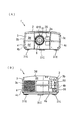
図1(A)、(B)は、それぞれ本実施形態の投写型表示装置の正面図、背面図である。図2(A)、(B)は、それぞれ本実施形態の投写型表示装置の平面図、底面図である。
An exemplary embodiment of the present invention will be described with reference to the drawings.
<overall structure>
1A and 1B are a front view and a rear view, respectively, of the projection display device of the present embodiment. 2A and 2B are a plan view and a bottom view, respectively, of the projection display device of the present embodiment.
これらの図1および図2に示すように、本実施形態に係る投写型表示装置1は、直方体形状をした外装ケース2を有している。外装ケース2は、基本的には、アッパーケース3と、ロアーケース4とから構成されている。
As shown in FIGS. 1 and 2, the
外装ケース2の後壁には、外部電力供給用のACインレット36や各種の入出力端子群50が配置されている。従って、利用者が通常、位置する装置側面部に信号ケーブル等が置かれないので、使い勝手がよい。
An
〈外装ケースの構造〉
外装ケース2のアッパーケース3は、長方形の上壁3aと、その四方の辺からほぼ垂直に下方に延びている左右の側壁3b、3c、前壁3d、および後壁3eから形成されている。ロアーケース4は、長方形の底壁4aと、その四方の辺からほぼ垂直に起立している左右の側壁4b、4c、前壁4d、および後壁4eから形成されている。
<Structure of exterior case>
The
アッパーケース3およびロアーケース4は、前方からみて中央部分からやや左寄りの部分が凹んでおり、そこに形成された円形の開口から投写レンズユニット6の前端側の部分が装置前方側に延びており、投写レンズユニット6の先端部は、外装ケース2前面から突出している。
The
この突出する部分のうち、ズームレンズを保持しているズームリング61には、その軸線方向に延びる1条のノブ等といった突起610が形成されている。このため、手探りでもズームリング61とフォーカスリング62とを判別でき、かつ、それを回すのに便利である。このような突起610はフォーカスリング62の動きを妨げない位置であればフォーカスリング62の方に形成してもよい。
Among the protruding portions, the
図1(A)に示すように、装置前面を規定しているアッパーケース3の前壁3dのうち、投写レンズユニット6の右側位置には受光窓35が設けられている。この受光窓35は、図示しないリモートコントローラからの制御光を受けるためのものである。
As shown in FIG. 1A, a
アッパーケース3の上壁3aの前方側の中央部分には、図2(A)に示すように、内蔵スピーカー(図示せず)に対応した位置に多数の連通孔25が形成されている。
As shown in FIG. 2 (A), a large number of communication holes 25 are formed in the center portion on the front side of the
また、上壁3aの前方側の中央部分には、操作部としての操作スイッチ26が設けられている。この操作スイッチ26に形成されている各スイッチ群のうち、主電源のオンオフを行うためのメインスイッチ261と、このメインスイッチ261に隣接する他のスイッチ263との間には、メインスイッチ261よりも突出した突出部である突条部262が形成されている。この突条部262は、平面視で円状に形成されたメインスイッチ261の周縁に沿って、円弧状に形成され、具体的には、メインスイッチ261の周縁全体における90度の角度範囲に設けられている。この円弧状の突条部262はメインスイッチ261の上端面よりも上方に突き出ているので、他のスイッチ263を触れるときに誤ってメインスイッチ261を押してしまうことがなく、誤操作を確実に防止できる。
In addition, an
一方、ロアーケース4の底壁4aの後端の中央にはフット31Cが配置され、前端の左右にはフット31R、31Lが配置されている。これらのフットのうち、左右のフット31R、31Lは、それを回すことによってフット高さ、つまり、底壁4aからの突出長さの調整ができる。
On the other hand, a
〈装置本体の内部構造〉
図3には、投写型表示装置1の外装ケース2の内部における各構成部分の配置を示してある。外装ケース2の内部には、前述した投写レンズユニット6を含む光学ユニット10および電源ユニット7が並設され、光学ユニット10の上には、装置駆動制御用の制御基板13およびビデオ基板11が積層配置されている。
<Internal structure of device body>
FIG. 3 shows the arrangement of the components in the
〈光学ユニット〉
光学ユニット10は、光源ランプ81(図4参照)をハウジング802内に収納した光源ランプユニット8と、この光源ランプユニット8から出射された光束を光学的に処理して画像情報に対応した光学像を形成する光学レンズユニット9と、この光学像を投写面上に拡大投写する投写レンズユニット6とを含んで構成されている。この光学ユニット10は、外装ケース2の内部空間において、後方からみてその右半分以上を占有している。
<Optical unit>
The
〈光学レンズユニット〉
光学レンズユニット9は、後述する各種光学素子を内蔵した箱状の上下のライトガイド901,902に、プリズムユニット910を取り付けた構造を備えている。これらの上ライトガイド901および下ライトガイド902は、それぞれ、図1および図2に示したアッパーケース3およびロアーケース4の側に固定ねじにより固定されている。
<Optical lens unit>
The
ライトガイド901,902の前側の中央部分には、平面視で矩形の切り欠き9001が形成され、この切欠き9001にプリズムユニット910が組み込まれている。
A
プリズムユニット910は、マグネシウムやアルミニウムのダイキャスト板である厚手のヘッド板903に取り付けられ、このヘッド板903を介してライトガイド901,902に固定されている。
The
ヘッド板903は、装置の幅方向に向けて垂直な姿勢で延びる垂直壁91と、この垂直壁91の下端から水平に延びる底壁92(図7参照)とから基本的に略L字型に構成され、この底壁92上にプリズムユニット910が固定されている。垂直壁91の中央部分には、プリズムユニット910からの出射光が通過するための矩形の開口(図示省略)が形成され、この開口に投写レンズユニット6の基端部が固定されている。このように、剛性の高い垂直壁91を挟み、位置合わせした状態で、プリズムユニット910および投写レンズユニット6が光学レンズユニット9に固定されるので、これらの一体性は高く、衝撃力等が作用しても、相互の位置ずれが発生するおそれは極めて少ないという利点がある。
The
この投写レンズユニット6の基端部は、光学レンズユニット9の前側の中央に位置し、その基端部の側方、つまりヘッド板903と外装ケース2の前壁3d,4dとの間には、投写レンズユニット6の外装ケース2からの突出長さに応じた隙間が形成されている。
The base end portion of the
このような光学レンズユニット9の後端部の電源ユニット7側の角部は、平面視でへこみ部とされ、このへこみ部分に光源ランプユニット8が組み込まれている。すなわち、光源ランプユニット8は、外装ケース2内において、電源ユニット7の後端部および光学レンズユニット9のへこみ部によって構成される略矩形の領域に配置されている。
The corner portion of the rear end portion of the
ここで、ロアーケース4の底壁4aには、光源ランプユニット8に対応する位置にランプ交換蓋27がねじ止めされており、ねじを緩めて蓋27を取り外すことにより、内蔵の光源ランプユニット8を交換できるようになっている。
Here, a
〈基板〉
光学ユニット10(光学レンズユニット9)の上面側には、装置駆動制御用の制御基板13がねじ止め固定され、その上面側にはこれと平行に、ビデオ信号処理回路が搭載されたビデオ基板11が配置されている。
<substrate>
On the upper surface side of the optical unit 10 (optical lens unit 9), a
制御基板13については、光学ユニット10の上面側にねじ止め固定されているため、制御基板13を光学ユニット10に固定した状態でOEM等で生産する際には、全ての組み立てが完了する前であっても外部給電さえすれば、制御基板13や光学ユニット10を試験用に駆動できる。この制御基板13のプリズムユニット910に対応した部分、つまり、プリズムユニット910と重なる部分には、切り欠き130が形成されている。
Since the
なお、各基板11,13間の電気的接続はコネクタ114,116によって行われる。
The electrical connection between the
〈電源ユニット〉
電源ユニット7は、表示装置1を後方から見て、外装ケース2の内部の左端、つまり、光学ユニット10の左側に配置されている。
<Power supply unit>
The
この電源ユニット7は、外装ケース2と光学ユニット10との隙間形状に合わせて、装置後方から装置前方に向けて配置された本体部分71と、本体部分71の前方端部で屈曲する延設部分72とからなるL字形状を備え、この延設部分72は、投写レンズユニット6の基端部の側方に位置している。
The
このように、電源ユニット7は、外装ケース2の前端部分から投写レンズユニット6の突出寸法を短くすればするほど広く空いてしまう投写レンズユニット6の基端部の側方位置の隙間を延設部分72が埋めるような構造になっている。従って、外装ケース2の内部を有効利用できるので、投写型表示装置1の小型化を図ることができる。
As described above, the
電源ユニット7は、金属製のL字状のシールドケース70に各種の電子部品を内蔵した構造とされ、これに用いるシールドケース70は、電源ユニット7の内部を冷却用空気が流れる際の通風路を構成している。また、シールドケース70は、電源ユニット7で発生する電気的、磁気的ノイズが外部に漏れることを防止するとともに、電源ユニット7に引き回されてきたAC入力ラインや出力線等を覆い、それから発生するノイズを遮断している。
The
このようなシールドケース70の内部には、図示しないが、一次側アクティブフィルタ、パワーサプライおよびバラスト等が収納され、これらは、各種の素子を回路基板に搭載した構造を有している。具体的には、一次側アクティブフィルタの回路基板には、発信用FET等の素子が搭載され、パワーサプライの基板には、整流用ダイオードブリッジ、D/Dコンバータ用発振トランジスタおよびD/Dコンバータ用3端子レギュレータ等が搭載され、バラストの回路基板には、チョッパー回路用ドライブFETおよびチョッパー回路用逆流防止用ダイオード等が搭載されている。これらの素子は発熱源となるため、ヒートシンクを固定して放熱させることで、冷却効率を高めるようにしている。
Although not shown, such a
なお、外装ケース2の内部は、無駄な隙間が発生しないように各種光学部品が密に配置されていることから、金属製の通常のシャーシを外装ケース2の全体に配置することは困難である。そこで、シート状のシールド材(図示せず)を被せるとともに、必要な箇所で折り曲げれば、無駄な隙間を発生させることなく全体を覆うことができる。
In addition, since various optical components are densely arranged inside the
〈光学系〉
図4を参照して、光学ユニット10に組み込まれている光学系について説明する。本実施形態の光学系は、光源ランプユニット8と、インテグレータレンズ921,922および偏光変換素子920を含む照明光学系923と、この照明光学系923から出射される光束Wを、赤、緑、青の各色光束R、G、Bに分離する色分離光学系924と、各色光束を変調する変調系(ライトバルブ)としての3枚の液晶ライトバルブ925R,925G,925Bと、変調された色光束を再合成する色合成光学系としてのプリズムユニット910と、合成された光束をスクリーン上に拡大投写する投写レンズユニット6とから構成される。
<Optical system>
With reference to FIG. 4, the optical system incorporated in the
光源ランプユニット8の光源ランプ81は、ハロゲンランプ等のランプ本体805と、リフレクタ806と、リフレクタ806の前面部に貼られたガラス面807とを備え、当該ガラス面807が露出するようにハウジング802(図3および図8参照)に収納されている。この光源ランプ81は、ランプ本体805からの光をガラス面807を通して、光学レンズユニット9のインテグレータレンズ921に向けて、装置1の前後方向と直交する方向に出射するようになっている。
The
なお、光源ランプ81としては、ハロゲンランプ、メタルハライドランプ、キセノンランプ等を用いることができる。
As the
照明光学系923は、微小レンズがマトリクス状に配置された二枚のインテグレータレンズ921,922と、これらのインテグレータレンズ921,922とほぼ平行に配置された偏光変換素子920と、この偏光変換素子920とほぼ直交するように配置された集光レンズ930とを含んで構成されている。この集光レンズ930の前段、つまり、偏光変換素子920および集光レンズ930の間には、反射ミラー931が配置され、光源ランプ81からの出射光の中心光軸1aを装置前方向に向けて直角に折り曲げるようにしている。
The illumination
インテグレータレンズ921は、光源ランプユニット8から出射された光束を複数の部分光束に分割し、各部分光束をインテグレータレンズ922の近傍で集光させる。
The
インテグレータレンズ922は、インテグレータレンズ921から出射された各部分光束の中心光路を光軸1aに対して平行に揃える機能を有している。光源ランプユニット8から出射される光束が光軸1aに完全に平行な光である場合には、インテグレータレンズ921から出射される部分光束も、その中心光路が光軸1aに平行となるので、光源ランプユニット8から出射される光束の平行度が高い場合には、インテグレータレンズ922を省略してもよい。
The
集光レンズ930は、各部分光束をライトバルブ925R,925G,925B上に重畳させる機能を有している。
The
このように、本実施形態の投写型表示装置1では、光源ランプユニット8から出射された光束を、インテグレータレンズ921によって複数の部分光束に分割し、それぞれの部分光束を、集光レンズ930によって液晶ライトバルブ925R,925G,925B上に重畳させるようにしているため、液晶ライトバルブ925R,925G,925Bをほぼ均一な照度の光で照明することができ、従って、照度ムラの少ない画像を得ることができる。
As described above, in the
偏光変換素子920は、偏光分離膜とλ/2位相差板との集合体によって、入射光をP偏光とS偏光とに分離した後、S偏光に揃えるものである。すなわち、図5に示すように、偏光変換素子920は、偏光ビームスプリッタアレイ9201と、選択位相差板9202とを備えている。偏光ビームスプリッタアレイ9201は、それぞれ断面が平行四辺形の柱状の複数の透光性板材9203が、交互に貼り合わされた形状を有している。透光性板材9203の界面には、偏光分離膜9204と反射膜9205とが交互に形成されている。なお、この偏光ビームスプリッタアレイ9201は、偏光分離膜9204と反射膜9205が交互に配置されるように、これらの膜が形成された複数枚の板ガラスを貼り合わせて、所定の角度で斜めに切断することによって作製される。
The
インテグレータレンズ921,922(図4参照)を通過したランダムな偏光方向を有する光は、偏光分離膜9204でs偏光光とp偏光光とに分離される。s偏光光は、偏光分離膜9204によってほぼ垂直に反射され、反射膜9205によってさらに垂直に反射されてから出射される。一方、p偏光光は、偏光分離膜9204をそのまま透過する。選択位相差板9202は、偏光分離膜9204を通過する光の出射面部分にλ/2位相差層9206が形成されており、反射膜9205で反射された光の出射面部分はλ/2位相差層が形成されていない光学素子である。従って、偏光分離膜9204を透過したp偏光光は、λ/2位相差層9206によってs偏光光に変換されて出射する。この結果、偏光変換素子920に入射したランダムな偏光方向を有する光束は、ほとんどs偏光光となって出射する。
Light having a random polarization direction that has passed through the
このようにS偏光のみを利用できるようにすると、P偏光およびS偏光が混在しているランダム偏光をそのまま利用する場合に比べて、後述する色分離光学系924のダイクロイックミラー941,942(図4参照)における色分離性が改善される。また、ミラーを用いて光束を反射しているが、S偏光はP偏光に比べて反射率が良いので、光量損失等を抑制することができるという利点もある。
In this way, when only S-polarized light can be used,
再び、図4に戻って説明する。色分離光学系924は、青緑反射ダイクイロックミラー941と、緑反射ダイクロイックミラー942と、反射ミラー943から構成される。
Again, referring back to FIG. The color separation
このような色分離光学系924では、光束Wは、まず、青緑反射ダイクロイックミラー941において、そこに含まれている赤色光束Rが通過し、後方の反射ミラー943で直角に反射されて、赤色光束の出射部944からプリズムユニット910の側に出射される。
In such a color separation
一方、光束Wに含まれる青色光束Bおよび緑色光束Gは、青緑反射ダイクロイックミラー941で直角に反射され、緑反射ダイクロイックミラー942の側に向かい、緑反射ダイクロイックミラー942において、緑色光束Gのみが直角に反射されて、緑色光束の出射部945からプリズムユニット910の側に出射される。この緑反射ダイクロイックミラー942を通過した青色光束Bは、導光系927を介して、青色光束の出射部946からプリズムユニット910の側に出射される。
On the other hand, the blue light beam B and the green light beam G included in the light beam W are reflected at a right angle by the blue-green reflecting
この導光系927は、青色光束Bを、対応する液晶ライトバルブ925Bに導くためのものであり、入射側反射ミラー971と、出射側反射ミラー972と、これらの間に配置した中間レンズ973と、入射側反射ミラー971の前段に配置した集光レンズ976から構成される。照明光学系923から各色光束R,G,Bの出射部944,945,946までの距離は、青色光束Bの場合が最も大きくなるが、このような導光系927を配置することにより、光の損失を防ぐようにしている。
The
色分離光学系924の赤色光束Rおよび緑色光束Gの各出射部944,945には、それぞれ集光レンズ951,952が配置されている。従って、各出射部944,945からそれぞれ出射した赤色光束Rおよび緑色光束Gは、これらの集光レンズ951,952に入射して平行化される。
Condensing
このように平行化された赤色光束Rおよび緑色光束Gは、それぞれ、各液晶ライトバルブ925R,925Gに対して配置された偏光板981,982を介して、液晶ライトバルブ925R,925Gに入射して変調され、各色光に対応した画像情報が付加される。すなわち、これらのライトバルブ925R,925Gは、図示しない駆動手段によって画像情報に応じてスイッチング制御されて、これにより、ここを通過する各色光の変調が行われる。
The collimated red light beam R and green light beam G are incident on the liquid crystal
これらの光束R,Gと同様に、導光系927を通過した青色光束Bは、当該青色光束Bの出射部946に配置された集光レンズ953に入射して平行化され、液晶ライトバルブ925Bに対して配置された偏光板983を通じて、液晶ライトバルブ925Bに入射し、ここにおいて、前述した赤色光束Rおよび緑色光束Gと同様に、画像情報に応じて変調が施される。
Similar to these light fluxes R and G, the blue light flux B that has passed through the
なお、液晶ライトバルブ925R,G,Bとしては、例えば、ポリシリコンTFTをスイッチング素子として用いたものを使用できる。 As the liquid crystal light valves 925R, G, and B, for example, those using polysilicon TFTs as switching elements can be used.
次に、各液晶パネル925R,G,Bを通って変調された各色光束は、前述のようにダイクロイリックプリズムからなるプリズムユニット910に入射して再合成される。ここで再合成されたカラー映像は、投写レンズユニット6を介して、所定の位置にある投写面としてのスクリーン上に拡大投写される。
Next, the light beams of the respective colors modulated through the respective liquid crystal panels 925R, G, and B are incident on the
本実施形態の光学ユニット10においては、これらの照明光学系923、色分離光学系924、液晶ライトバルブ925R,925G,925B、偏光板981〜983、および導光系927は、前述したライトガイド901,902(図3参照)内に光軸を合わせた状態で位置決め固定されている。
In the
このように構成された本実施形態では、光源ランプユニット8から出射された光束は、反射ミラー931によって反射されて大回りのL字形の光路を進行し、色分離光学系924を介してプリズムユニット910に到達する。従って、各光学部品が狭い領域内に配置されている割りには光路を最大限長く設定してある。それ故、F値の小さなレンズを用いながら、かつ、インテグレータレンズ921,922や偏光変換素子920の配置位置を十分に確保しながら、光源ランプユニット8から出射された光束を平行光束として液晶ライトバルブ925R、925Gに到達させることができる。また、インテグレータレンズ921,922の配置領域を十分広く確保できる分、その分割数を増やすことができる。従って、インテグレータレンズ921,922を接近して配置することができ、結果的には小型化を図ることができる。
In the present embodiment configured as described above, the light beam emitted from the light
〈吸気口および吸気ファン等の配置〉
次に、本実施形態の投写型表示装置1における冷却のための構造を、図3、図6および図7を参照して説明する。本実施形態の装置1では、外装ケース2に形成された冷却用空気取り入れ口150から吸い込んだ外気(冷却用空気)を、外装ケース2内で循環させて、外装ケース2後端面の排気口160から排出することで、ケース2内の各発熱源を冷却するように構成されている。
<Arrangement of intake port and intake fan>
Next, a cooling structure in the
すなわち、冷却用空気取り入れ口150(吸気口)は、図3に示すように、外装ケース2の底面部となるロアーケース4の底壁4aに形成された多数の通気孔151により構成されている。これらの通気孔151は、ロアーケース4の底壁4aのうち、プリズムユニット910の下方領域150Aおよび投写レンズユニット6の基端部の下方領域150Bにわたって形成されている。
That is, as shown in FIG. 3, the cooling air intake port 150 (intake port) is configured by a large number of ventilation holes 151 formed in the
このような通気孔151が形成された領域150A,150B全体には、ロアーケース4の底壁4aの下方からスポンジ状のエアーフィルタ241が被せられ、このエアーフィルタ241は、ロアーケース4の底壁4aにねじ止め固定されたエアーフィルタカバー23によって保持されている。このエアーフィルタカバー23にも多数の通気孔231が形成されている。このように、エアーフィルタ241は、底壁4aにおいて、光学レンズユニット9の配置領域150Aおよび投写レンズユニット6の下方の領域150Bの双方に跨がって設置されているので、そこは1枚のエアーフィルタ241で足りる。それ故、エアーフィルタ241を交換する手間が減る分、使い勝手がよい。また、防塵という面での信頼性が高い。
このような冷却用空気取り入れ口150の後半分、つまり、プリズムユニット910の下方領域150Aには、冷却用の吸気ファン15が設けられている。この吸気ファン15は、図7に示すように、プリズムユニット910を搭載した前記ヘッド板903の底壁92の下面に固定されている。このヘッド板903の底壁92には、吸引した冷却用空気を流通させるための通気孔(図示省略)が形成されている。
A
また、冷却用空気取り入れ口150の前半分となる投写レンズユニット6の下方領域150Bは、投写レンズユニット6の基端部の側方に位置する電源ユニット7の延設部分72近傍に形成される。図6に示すように、この延設部分72の端部となるシールドケース70の投写レンズユニット6側の端面は、ケース70内に形成された通風路の入口とされ、本体部分71の後端部になるシールドケース70の端面は、通風路の出口とされている。
In addition, a
通風路の入口には、冷却用空気導入手段としての補助冷却ファン17(電源ユニット7内に冷却用空気を吸引するための吸気ファン)が取り付けられ、シールドケース70前部の入口から通風路に空気を取り入れて、ケース70後部の出口から通風路の空気を排気するようになっている。
An auxiliary cooling fan 17 (an intake fan for sucking cooling air into the power supply unit 7) as cooling air introduction means is attached to the inlet of the ventilation path, and the inlet from the front part of the
この補助冷却ファン17と、投写レンズユニット6の下方領域150Bとは、図3にも示すように、空気通路を区画形成するダクト部であるダクトカバー170(冷却用空気導入手段)で接続され、冷却用空気取り入れ口150から外気を直接電源ユニット7内に吸引するようになっている。
As shown in FIG. 3, the
一方、装置後端側、具体的には、電源ユニット7および光源ランプユニット8の後方には、排気ファン16を備えた排気口160が設けられている。このように排気口160を装置後端部に設けると、通常、利用者が位置する装置側面部から排気されないので、装置1の使い勝手がよい。排気ファン16は、光源ランプユニット8のハウジング802の後側面に形成された開口を覆うように当該ハウジング802に取り付けられ、ハウジング802内部を通じて外装ケース2内の空気を排出するように構成されている。
On the other hand, an
〈冷却用空気の流れ〉
このように構成された投写型表示装置1では、プリズムユニット910の下方位置には、冷却用の吸気ファン15を具備する冷却用空気取り入れ口150が設けられ、かつ、プリズムユニット910は、投写レンズユニット6に面する前側面以外の側面が、所定の隙間を隔てて液晶ライトバルブ925R,925G,925B等で囲まれている。しかも、光学ユニット10の上面側に被せられた制御基板13のうち、プリズムユニット910に対応する部分は、切り欠き130になっており、その上方にビデオ基板11が被さっている状態にある。それ故、冷却用空気取り入れ口150から取り入れた空気は、排気ファン16に吸引され、図7中矢印A1で示すように、プリズムユニット910の各端面に沿って上昇していき、プリズムユニット910、液晶ライトバルブ925R,925G,925Bおよび偏光板981〜983を冷却する。プリズムユニット910の上方に抜けた冷却用空気は、図6および図7中矢印A2で示すように、排気ファン16に吸引されてビデオ基板11と制御基板13との間を通って光源ランプユニット8の方に流れ、光源ランプユニット8を冷却した後、排気口160から排出される。従って、外装ケース2の底面部から取り入れた冷却用空気で基板11,13上の回路を冷却するような空気通路を構成することができる。しかも、基板11,13を冷却した後、最も高温になる光源ランプユニット8を冷却するので、冷却効率が高い。
<Flow of cooling air>
In the
このように、外装ケース2の底面部に設けた冷却用空気取り入れ口150から取り入れた冷却用空気で少なくともプリズムユニット910、液晶ライトバルブ925R,925G,925B、偏光板981,982,983、および光源ランプユニット8を冷却できるので、各部品を狭い領域内に配置した場合でも効率よく冷却することができ、信頼性が向上する。
As described above, at least the
また、冷却用空気取り入れ口150からは、電源ユニット7に設けた補助冷却ファン17によっても冷却用空気(外気)が吸い込まれ、この空気は、図6中矢印A3で示すように、ダクトカバー170を通って電源ユニット7内、つまり、シールドケース70内の通風路に引き込まれる。そこで、冷却用空気は、排気ファン16に吸引されながら、延設部分72から本体部分71に向かって電源ユニット7の内部を冷却しながら通り抜け、排気口160から外部に排出される。
Cooling air (outside air) is also sucked in from the cooling
この電源ユニット7では、素子に取り付けたヒートシンクが高温になるため、このヒートシンクを冷却する必要が生じるが、冷却用空気取り入れ口150から取り入れた冷却用空気(外気)を直接シールドケース70内の通風路に導入するので、ヒートシンクを効率よく確実に冷却できる。すなわち、外気を電源ユニット7に直接供給するので、外装ケース2内の空気、つまり、電源ユニット7以外の部品を冷却した後の空気を電源ユニット7に導入するよりも、低温な冷却用空気を電源ユニット7に供給できるから、ヒートシンクから熱を効率よく奪うことができる。
In this
とくに、補助冷却ファン17と冷却用空気取り入れ口150の前半分とはダクトカバー170により連結されているため、外装ケース2の外部の低温な外気のみをシールドケース70内の通風路に導入できるから、電源ユニット7の冷却効率を一層高めることができる。
In particular, since the
また、補助冷却ファン17を用いることで、多量の外気を通風路に安定供給できるので、電源ユニット7を効率よく確実に冷却できる。
Further, since the
さらに、この補助冷却ファン17は、ダクトカバー170を介して冷却用空気取り入れ口150に接続されているので、ファン17を作動させても、投写レンズユニット6および外装ケース2の間の隙間等から異物の混入した外気が外装ケース2内に吸引されることを確実に防止できる。従って、異物の光学系への付着を回避できるので、表示の品位を維持できるから、充分な信頼性を確保できる。
Further, since the
ここで、図3および図6に示すように、制御基板13のうち、発熱源となるプリズムユニット910や液晶ライトバルブ925R,925G,925Bに近い位置、および発熱源である光源ランプユニット8に近い位置には、それぞれ温度センサS1,S2が直に搭載されている。これにより、これらの発熱源を通って発熱した空気の温度を測定できるため、異常な温度上昇を監視できる。また、温度センサS1,S2を制御基板13上に直に搭載してある分、そのための配線を省略できる。
Here, as shown in FIGS. 3 and 6, the
〈偏光変換素子等の冷却〉
本実施形態の光学ユニット10においては、図8に示すように、インテグレータレンズ921,922および偏光変換素子920の間には、それぞれ上下方向に貫通する通風路としての隙間が確保されている。また、下ライトガイド902のうち、インテグレータレンズ921,922および偏光変換素子920の下方となる領域には、複数の吸気口909が形成されている。これらの隙間および吸気口909により、インテグレータレンズ921,922および偏光変換素子920の光入射面および光出射面の少なくともいずれか一方に沿って冷却用空気を流通させるための通風路が構成されている。
<Cooling of polarization conversion element, etc.>
In the
また、インテグレータレンズ921,922および偏光変換素子920の上方位置には、これらの光学素子の光入射面および光出射面の少なくともいずれか一方に沿って流通してきた冷却用空気を、光源ランプユニット8のハウジング802に設けられたフード848に導くためのガイド板89が配置されている。
In addition, cooling air that has circulated along at least one of the light incident surface and the light emitting surface of these optical elements is provided above the
これらのレンズ921,922および偏光変換素子920等の光学素子の冷却は、前述した冷却用空気取り入れ口150から吸気ファン15で吸い込まれた冷却用空気により行う。
Cooling of the optical elements such as the
すなわち、冷却用空気取り入れ口150から外装ケース2内に取り込まれた冷却用空気は、光源ランプユニット8の背後に配置した排気ファン16に吸引されて、下ライトガイド902の吸気口909を通じて光学レンズユニット9内に吸い込まれる。この吸い込まれた冷却用空気は、図8中矢印A7で示すように、インテグレータレンズ921,922および偏光変換素子920の光入射面および光出射面の少なくともいずれか一方に沿って通風路を上昇し、これらの光学素子を冷却する。
That is, the cooling air taken into the
光学素子のうち、とくに、偏光変換素子920では、入射したs偏光光が、偏光分離膜9204および反射膜9205(図5参照)で若干吸収されて発熱するので、冷却の必要性が生じる。本実施形態の装置1では、この偏光変換素子920に沿って冷却用空気を流通させる通風路が設けられているので、偏光変換素子920を確実に冷却することができる。
Among the optical elements, in particular, in the
これらの偏光変換素子920およびインテグレータレンズ921,922を冷却して上昇した冷却用空気は、図8中矢印A8で示したように、ガイド板89に沿ってハウジング802のフード848に導かれ、ハウジング802内に導入されて光源ランプ81を冷却した後に、排気口160から排出されることになる。
The cooling air that has risen by cooling the
従って、ガイド板89により、偏光変換素子920およびインテグレータレンズ921,922を冷却した後の冷却用空気を光源ランプユニット8の方へ導くことができるので、高温になりやすい光源ランプユニット8を効率よく確実に冷却できる。
Accordingly, since the
また、光学レンズユニット9内に取り込まれた冷却用空気の一部は、排気ファン16に吸引されてそのまま光源ランプユニット8に向かい、図8中矢印A9で示すように、光源ランプ81のガラス面807に沿って上昇し、当該ガラス面807を冷却する。このようにガラス面807を冷却した後の空気は、ハウジング802のフード848や、光源ランプ81およびハウジング802の間の隙間を通ってハウジング802内に吸い込まれ、光源ランプ81を冷却し、しかる後に、排気口160から排出される。
Further, a part of the cooling air taken into the
それ故、光源ランプ81や光学素子に対する冷却効率が高いので、高い信頼性が得られるうえ、光源ランプ81の交換頻度が少なくて済むので、使い勝手も向上する。
Therefore, since the cooling efficiency with respect to the
なお、以上に述べた実施形態では、電源ユニット7の通風路の入口を、シールドケース70の投写レンズユニット6側の端面に形成した場合について説明したが、例えば、通風路の入口は、シールドケースの投写面側の前方側面に形成してもよい。この場合、外装ケースの投写面側の側面に冷却用空気取り入れ口を設けて、この冷却用空気取り入れ口および通風路の入口を直接接続してもよい。
In the embodiment described above, the case where the inlet of the ventilation path of the
本発明は、投写型表示装置に利用することができる。 The present invention can be used for a projection display device.
1…投写型表示装置、2…外装ケース、3…アッパーケース、4…ロアーケース、6…投写レンズユニット、7…電源ユニット、8…光源ランプユニット、9…光学レンズユニット、10…光学ユニット、15…吸気ファン、16…排気ファン、17…補助冷却ファン(冷却用空気導入手段)、23…エアーフィルタカバー、26…操作スイッチ(操作部)、81…光源ランプ、802…ハウジング、89…ガイド板(ガイド)、150…冷却用空気取り入れ口、160…排気口、170…ダクトカバー(冷却用空気導入手段)、241…エアーフィルタ、261…メインスイッチ、262…突条部(突出部)、901,902…ライトガイド、909…吸気口、910…プリズムユニット、920…偏光変換素子、923…照明光学系、924…色分離光学系、925R、925G、925B…液晶ライトバルブ、927…導光系、S1,S2…温度センサ
DESCRIPTION OF
Claims (6)
電源ユニットと、
前記光源ランプ、前記光学系、前記投写レンズユニットおよび電源ユニットとを収納する外装ケースと、
前記光源ランプの近傍で前記外装ケース内からの排気を行う排気ファンとを備えた投写型表示装置であって、
前記光学系は、前記光源ランプの出射面に対向配置されかつ前記光源ランプから出射された光束を二種類の直線偏光成分に分離してこれらの直線偏光成分の偏光方向を揃える偏
光変換素子を備え、
前記外装ケース内には、前記光学系を収容するとともに、前記偏光変換素子に応じた位置に吸気口が形成されたライトガイドが配置され、
前記外装ケースには、冷却用空気取り入れ口が形成されており、
前記電源ユニットの内部に設けられた冷却用空気を流通させるための通風路と、
前記冷却用空気取り入れ口の一部から前記通風路の入口に前記外装ケースの外部の外気を直接導入するための冷却用空気導入手段とを備え、
前記冷却用空気導入手段は、前記冷却用空気取り入れ口の一部を覆い、この冷却用空気取り入れ口の一部と、前記電源ユニットの通風路の入口とを連結するダクト部を有し、
前記外装ケースに形成された前記冷却用空気取り入れ口からの空気の一部は、前記冷却用空気導入手段により、前記電源ユニット内部に直接導入され、
前記冷却用空気取り入れ口からの他の一部の空気は、前記ライトガイドと外装ケースとの間を通り、前記ライトガイドの吸気口からライトガイド内部に導入され、前記偏光変換素子の光入射面および光出射面の少なくともいずれか一方に沿って流通する通風路が設けられていることを特徴とする投写型表示装置。 A light source lamp, an optical system that optically processes a light beam emitted from the light source lamp to form an optical image corresponding to image information, a projection lens unit that magnifies and projects the optical image, and
A power supply unit;
An exterior case that houses the light source lamp, the optical system, the projection lens unit, and a power supply unit;
A projection display device comprising an exhaust fan for exhausting air from the exterior case in the vicinity of the light source lamp,
The optical system includes a polarization conversion element that is disposed opposite to an emission surface of the light source lamp and separates a light beam emitted from the light source lamp into two types of linearly polarized light components and aligns the polarization directions of these linearly polarized light components. ,
In the outer case, a light guide that houses the optical system and in which an air inlet is formed at a position corresponding to the polarization conversion element is disposed,
The outer case is formed with an air intake for cooling,
A ventilation path for circulating cooling air provided in the power supply unit;
Cooling air introduction means for directly introducing outside air outside the outer case from a part of the cooling air intake port to the inlet of the ventilation path,
The cooling air introduction means has a duct portion that covers a part of the cooling air intake and connects a part of the cooling air intake and the inlet of the ventilation path of the power supply unit,
A part of the air from the cooling air inlet formed in the outer case is directly introduced into the power supply unit by the cooling air introduction means,
Another part of the air from the cooling air intake port passes between the light guide and the outer case, and is introduced into the light guide from the light guide intake port, and the light incident surface of the polarization conversion element And a ventilation passage that circulates along at least one of the light exit surface.
前記偏光変換素子の光入射面および光出射面の少なくともいずれか一方に沿って流通した冷却用空気を前記光源ランプの方に導くためのガイドが配置されていることを特徴とする投写型表示装置。 The projection display device according to claim 1,
A projection display device comprising: a guide for guiding cooling air flowing along at least one of a light incident surface and a light output surface of the polarization conversion element toward the light source lamp. .
前記外装ケースには、主電源をオン・オフするためのメインスイッチを含む複数のスイッチを備えた操作部が設けられ、
前記メインスイッチと、このメインスイッチに隣接した前記スイッチとの間には、当該メインスイッチよりも突出した突出部が設けられていることを特徴とする投写型表示装置。 The projection display device according to claim 1 or 2,
The outer case is provided with an operation unit including a plurality of switches including a main switch for turning on and off the main power source,
A projection-type display device, wherein a projecting portion projecting from the main switch is provided between the main switch and the switch adjacent to the main switch.
前記突出部は、前記メインスイッチの周縁に沿って設けられていることを特徴とする投写型表示装置。 The projection display device according to claim 3,
The projection display device, wherein the protrusion is provided along a peripheral edge of the main switch.
前記光学系の上には、回路基板が配置され、
この回路基板における前記光源ランプ近傍には、温度センサが搭載されていることを特徴とする投写型表示装置。 In the projection display device according to any one of claims 1 to 4,
A circuit board is disposed on the optical system,
A projection display device, wherein a temperature sensor is mounted in the vicinity of the light source lamp on the circuit board.
前記光学系は、プリズムユニットを備え、The optical system includes a prism unit,
前記プリズムユニット上には、一対の回路基板が略平行に配置されており、On the prism unit, a pair of circuit boards are arranged substantially in parallel,
前記回路基板のうち、前記プリズムユニットに隣接する一方の回路基板には、前記プリズムユニットに対応する部分に切欠きが形成されており、 Of the circuit boards, one circuit board adjacent to the prism unit has a notch formed in a portion corresponding to the prism unit,
前記冷却用空気取り入れ口からの他の一部の空気は、前記プリズムユニットにも供給され、前記一方の回路基板の切欠きを介して一対の回路基板間に通して前記一対の回路基板Another part of the air from the cooling air intake port is also supplied to the prism unit, and passes between the pair of circuit boards through the notch of the one circuit board, so that the pair of circuit boards
を冷却する通風路を備えることを特徴とする投写型表示装置。A projection display device comprising an air passage for cooling the air.
Priority Applications (1)
| Application Number | Priority Date | Filing Date | Title |
|---|---|---|---|
| JP2004220678A JP3671977B2 (en) | 1996-10-04 | 2004-07-28 | Projection display |
Applications Claiming Priority (3)
| Application Number | Priority Date | Filing Date | Title |
|---|---|---|---|
| JP26495196 | 1996-10-04 | ||
| JP28569096 | 1996-10-28 | ||
| JP2004220678A JP3671977B2 (en) | 1996-10-04 | 2004-07-28 | Projection display |
Related Parent Applications (1)
| Application Number | Title | Priority Date | Filing Date |
|---|---|---|---|
| JP22954197A Division JP3598752B2 (en) | 1996-10-04 | 1997-08-26 | Projection display device |
Publications (2)
| Publication Number | Publication Date |
|---|---|
| JP2004361971A JP2004361971A (en) | 2004-12-24 |
| JP3671977B2 true JP3671977B2 (en) | 2005-07-13 |
Family
ID=34068814
Family Applications (1)
| Application Number | Title | Priority Date | Filing Date |
|---|---|---|---|
| JP2004220678A Expired - Lifetime JP3671977B2 (en) | 1996-10-04 | 2004-07-28 | Projection display |
Country Status (1)
| Country | Link |
|---|---|
| JP (1) | JP3671977B2 (en) |
-
2004
- 2004-07-28 JP JP2004220678A patent/JP3671977B2/en not_active Expired - Lifetime
Also Published As
| Publication number | Publication date |
|---|---|
| JP2004361971A (en) | 2004-12-24 |
Similar Documents
| Publication | Publication Date | Title |
|---|---|---|
| JP3598752B2 (en) | Projection display device | |
| US6364492B1 (en) | Projector | |
| JP3797129B2 (en) | Optical component mounting structure and projector | |
| JP4093073B2 (en) | projector | |
| US7806532B2 (en) | Projector for projecting an optical image formed by light modulated by a light modulating device | |
| US7018048B2 (en) | Projector exhaust fan | |
| JP3598763B2 (en) | Projection display device | |
| JP3613010B2 (en) | Projection display | |
| US6846079B2 (en) | Polarization converter, illumination optical device having the polarization converter and projector | |
| JP4853209B2 (en) | Light source cooling mechanism and projector | |
| JP2005338236A (en) | projector | |
| USRE40397E1 (en) | Optical device and projector | |
| JP2000221598A (en) | Projection display device | |
| JP4914077B2 (en) | Projection type image display device | |
| JP3567743B2 (en) | Projection display device | |
| JP2009042329A (en) | Image projection device | |
| JP2004361971A (en) | Projection display device | |
| JP4423997B2 (en) | projector | |
| JP5176457B2 (en) | projector | |
| JP3598760B2 (en) | Projection display device | |
| JP2007047661A (en) | projector | |
| JP3772848B2 (en) | projector | |
| JP2006072138A (en) | Rear projector | |
| JP2007033800A (en) | projector | |
| JP2018004849A (en) | Cooling mechanism of liquid crystal projector |
Legal Events
| Date | Code | Title | Description |
|---|---|---|---|
| A131 | Notification of reasons for refusal |
Free format text: JAPANESE INTERMEDIATE CODE: A131 Effective date: 20050105 |
|
| A521 | Written amendment |
Free format text: JAPANESE INTERMEDIATE CODE: A523 Effective date: 20050307 |
|
| TRDD | Decision of grant or rejection written | ||
| A01 | Written decision to grant a patent or to grant a registration (utility model) |
Free format text: JAPANESE INTERMEDIATE CODE: A01 Effective date: 20050329 |
|
| A61 | First payment of annual fees (during grant procedure) |
Free format text: JAPANESE INTERMEDIATE CODE: A61 Effective date: 20050411 |
|
| R150 | Certificate of patent or registration of utility model |
Free format text: JAPANESE INTERMEDIATE CODE: R150 |
|
| FPAY | Renewal fee payment (event date is renewal date of database) |
Free format text: PAYMENT UNTIL: 20080428 Year of fee payment: 3 |
|
| FPAY | Renewal fee payment (event date is renewal date of database) |
Free format text: PAYMENT UNTIL: 20090428 Year of fee payment: 4 |
|
| FPAY | Renewal fee payment (event date is renewal date of database) |
Free format text: PAYMENT UNTIL: 20090428 Year of fee payment: 4 |
|
| FPAY | Renewal fee payment (event date is renewal date of database) |
Free format text: PAYMENT UNTIL: 20100428 Year of fee payment: 5 |
|
| FPAY | Renewal fee payment (event date is renewal date of database) |
Free format text: PAYMENT UNTIL: 20110428 Year of fee payment: 6 |
|
| FPAY | Renewal fee payment (event date is renewal date of database) |
Free format text: PAYMENT UNTIL: 20110428 Year of fee payment: 6 |
|
| FPAY | Renewal fee payment (event date is renewal date of database) |
Free format text: PAYMENT UNTIL: 20120428 Year of fee payment: 7 |
|
| FPAY | Renewal fee payment (event date is renewal date of database) |
Free format text: PAYMENT UNTIL: 20130428 Year of fee payment: 8 |
|
| FPAY | Renewal fee payment (event date is renewal date of database) |
Free format text: PAYMENT UNTIL: 20130428 Year of fee payment: 8 |
|
| FPAY | Renewal fee payment (event date is renewal date of database) |
Free format text: PAYMENT UNTIL: 20140428 Year of fee payment: 9 |
|
| S531 | Written request for registration of change of domicile |
Free format text: JAPANESE INTERMEDIATE CODE: R313531 |
|
| R350 | Written notification of registration of transfer |
Free format text: JAPANESE INTERMEDIATE CODE: R350 |
|
| EXPY | Cancellation because of completion of term |