JP3673387B2 - Musical sound channel assignment apparatus and musical sound channel assignment method - Google Patents
Musical sound channel assignment apparatus and musical sound channel assignment method Download PDFInfo
- Publication number
- JP3673387B2 JP3673387B2 JP01278198A JP1278198A JP3673387B2 JP 3673387 B2 JP3673387 B2 JP 3673387B2 JP 01278198 A JP01278198 A JP 01278198A JP 1278198 A JP1278198 A JP 1278198A JP 3673387 B2 JP3673387 B2 JP 3673387B2
- Authority
- JP
- Japan
- Prior art keywords
- channel
- data
- sound
- envelope
- musical
- Prior art date
- Legal status (The legal status is an assumption and is not a legal conclusion. Google has not performed a legal analysis and makes no representation as to the accuracy of the status listed.)
- Expired - Fee Related
Links
Images








Landscapes
- Electrophonic Musical Instruments (AREA)
Description
【0001】
【発明の属する技術分野】
本発明は、楽音のチャンネル割り当て装置または楽音のチャンネル割り当て方法に関し、特に同じ周波数の楽音の合成の制御に関する。
【0002】
【従来技術】
従来、電子楽器のチャンネル割り当て装置では、同時に発音できる楽音数より多くない数の楽音生成チャンネルが時分割処理により構成され、新たな楽音の発生の指示があると、この楽音が上記複数のチャンネルの空きチャンネルに割り当てられ、これにより楽音が発生される。
【0003】
この各チャンネルに割り当てられる楽音は、キーボードの各キーの操作に応じており、音高(周波数)が異なっている。この楽音の波形は同じであったり異なっていたりする。この楽音の波形が異なれば音色も異なる。
【0004】
【発明が解決しようとする課題】
ところが、各チャンネルに割り当てられる複数の楽音の中には場合によって同じ音高(周波数)のものがあり、このような同じ周波数の楽音に別々のチャンネルを割り当てるのは無駄であった。また、それぞれ個別に生成されるエンベロープの楽音の中にも場合によって同じ音高(周波数)のものがあり、このような同じ周波数の楽音に別々のエンベロープを付加するのは無駄であった。
【0005】
【課題を解決するための手段】
上記目的を達成するため、本発明では、同時に発生される複数の楽音のうち、同じ周波数の楽音を判別し、この判別された同じ周波数の楽音の発生量を合成して、1つのチャンネルにまとめて割り当て、各チャンネルに割り当てられている各楽音につき、チャンネル明け渡しの優先順位を決定し、この決定された優先順位に基づいてチャンネルを選び出し、このチャンネルに割り当てられている楽音を急速に減衰し、この急速な減衰が達成されたとき、当該チャンネルに新たな楽音を割り当てるようにした。
【0006】
これにより、使用するチャンネルの数を減らしてチャンネルの有効利用を図ることができ、空きチャンネルがないとき新たな楽音にチャンネルを明け渡して(トランケート)して、新たな楽音に確実にチャンネルを割り当てることができるし、上記急速な減衰によって新たな楽音へのチャンネル割り当てを迅速に行うことができる。
【0007】
【発明の実施の形態】
1.全体回路
図1は楽音制御装置または電子楽器の全体回路を示す。キーボード11の各キーは、楽音の発音及び消音を指示するもので、キースキャン回路12によってスキャンされ、キーオン、キーオフを示すデータが検出され、コントローラ2によってプログラム/データ記憶部4に書き込まれる。そして、それまでプログラム/データ記憶部4に記憶されていた各キーのオン、オフの状態を示すデータと比較され、各キーのオンイベント、オフイベントの判別が、コントローラ2によって行われる。
【0008】
このキーボード11の各キーには段差タッチスイッチが設けられ、各段差スイッチごとに上記スキャンが行われ、各段差スイッチの先頭のオン/オフごとにオンイベント/オフイベントの検出が行われる。この段差スイッチによってタッチの速さと強さを示す上記タッチ情報つまりイニシャルタッチデータとアフタタッチデータとが発生される。
【0009】
このキーボード11は、ローアキーボード、アッパーキーボード、ペダルキーボード等から成っており、それぞれにつき異なる音色の楽音、つまりエンベロープ波形の異なる楽音が発音される。そして、アッパーキーボードについては、1つのキーオンで2音色の楽音を同時に鳴らすことも可能である。なお、キーボード11は、電子弦楽器、電子吹奏(管)楽器、電子打楽器(パッド等)、コンピュータのキーボード等で代用される。
【0010】
パネルスイッチ群13の各スイッチは、パネルスキャン回路14によって、スキャンされる。このスキャンにより、各スイッチのオン、オフを示すデータが検出され、コントローラ2によってプログラム/データ記憶部4に書き込まれる。そして、それまでプログラム/データ記憶部4に記憶されていた各スイッチのオン、オフの状態を示すデータと比較され、各スイッチのオンイベント、オフイベントの判別が、コントローラ2によって行われる。
【0011】
ミディインターフェース15は、外部接続された電子楽器との間で楽音データの送受を行うためのインタフェースである。この楽音データはMIDI(ミュージカルインスツルメントデジタルインタフェース)規格のもので、この楽音データに基づいた発音も行われる。
【0012】
上記キーボード11またはミディインターフェース15には、自動演奏装置も含まれる。これらキーボード11、パネルスイッチ群13及びミディインターフェース15から発生された演奏情報(楽音発生情報)は、楽音を発生させるための情報である。
【0013】
上記演奏情報(楽音発生情報)は、音楽的ファクタ(因子)情報であり、音高(音域)情報(音高決定因子)、発音時間情報、演奏分野情報、発音数情報、共鳴度情報などである。発音時間情報は楽音の発音開始からの経過時間を示す。演奏分野情報は、演奏パート情報、楽音パート情報、楽器パート情報等を示し、例えばメロディ、伴奏、コード、ベース、リズム、MIDI等に対応したり、または上鍵盤、下鍵盤、足鍵盤、ソロ鍵盤、MIDI等に対応している。
【0014】
上記音高情報はキーナンバデータKNとして取り込まれる。このキーナンバデータKNはオクターブデータ(音域データ)と音名データとからなる。演奏分野情報は、パートナンバデータPNとして取り込まれ、このパートナンバデータPNは各演奏エリアを識別するデータであって、発音操作された楽音がどの演奏エリアからのものかによって設定される。
【0015】
発音時間情報は、トーンタイムデータTMとして取り込まれ、後述のフローチャートによって求められたり、キーオンイベントからのタイムカウントデータに基づいたり、またはエンベロープフェーズで代用される。この発音時間情報は特願平6−219324号明細書及び図面に発音開始からの経過時間情報として詳しく示される。
【0016】
発音数情報は同時に発音している楽音の数を示し、例えばアサインメントメモリ40のオン/オフデータが「1」の楽音の数に基づき、この数は特願平6−242878号の図9及び図15、特願平6−2476855号の図8及び図18、特願平6−276857号の図9及び図20、特願平6−276858号の図9及び図21のフローチャートに基づいて求められる。
【0017】
共鳴度情報は、同時に発音している1つの楽音と他の楽音との共鳴度を示す。この1つの楽音の音高周波数と他の楽音の音高周波数とが1:2、2:3、3:4、4:5、5:6など小さい整数数倍比であれば共鳴度情報の値は大きく、9:8、15:8、15:16、45:32、64:45など大きい整数数倍比であれば共鳴度情報の値は小さくなる。この共鳴度情報は特願平1−314818号の第7図の共鳴相関テーブル53または共鳴比率テーブル54から読み出される。
【0018】
さらに、上記パネルスイッチ群13には各種スイッチが設けられ、この各種スイッチは音色タブレット、エフェクトスイッチ、リズムスイッチ、ペダル、ホイール、レバー、ダイヤル、ハンドル、タッチスイッチ等であって楽器用のものである。このペダルはダンパーペダル、サスティンペダル、ミュートペダル、ソフトペダル等である。
【0019】
この各種スイッチより、楽音制御情報が発生され、この楽音制御情報は発生された楽音を制御する情報であって音楽的ファクタ(因子)情報であり、音色情報(音色決定因子)、タッチ情報(発音指示操作の速さ/強さ)、発音数情報、共鳴度情報、エフェクト情報、リズム情報、音像(ステレオ)情報、クオンタイズ情報、変調情報、テンポ情報、音量情報、エンベロープ情報等である。これら音楽的ファクタ情報も上記演奏情報(楽音情報)に合体され、上記各種スイッチより入力されるほか、上記自動演奏情報に合体されたり、上記インターフェースで送受される演奏情報に合体される。
【0020】
上記音色情報は、鍵盤楽器(ピアノ等)、管楽器(フルート等)、弦楽器(バイオリン等)、打楽器(ドラム等)の楽器(発音媒体/発音手段)の種類等に対応しており、トーンナンバデータTNとして取り込まれる。上記エンベロープ情報は、エンベロープレベルEL、エンベロープタイムET、エンベロープフェーズEFなどである。
【0021】
このような音楽的ファクタ情報は、コントローラ2へ送られ、後述の各種信号、データ、パラメータの切り換えが行われ、楽音の内容が決定される。上記演奏情報(楽音発生情報)及び楽音制御情報はコントローラ2で処理され、各種データが楽音信号発生部5へ送られ、楽音波形信号MWが発生される。コントローラ2はCPU、ROM及びRAMなどからなっている。
【0022】
プログラム/データ記憶部4(内部記憶媒体/手段)はROMまたは書き込み可能なRAM、フラッシュメモリまたはEEPROM等の記憶装置からなり、光ディスクまたは磁気ディスク等の情報記憶部7(外部記憶媒体/手段)に記憶されるコンピュータのプログラムが書き写され記憶される(インストール/転送される)。またプログラム/データ記憶部4には外部の電子楽器またはコンピュータから上記MIDI装置または送受信装置を介して送信されるプログラムも記憶される(インストール/転送される)。このプログラムの記憶媒体は通信媒体も含む。
【0023】
このインストール(転送/複写)は、情報記憶部7が本楽音生成装置にセットされたとき、または本楽音生成装置の電源が投入されたとき自動的に実行され、または操作者による操作によってインストールされる。上記プログラムは、コントローラ2が各種処理を行うための後述するフローチャートに応じたプログラムである。
【0024】
なお、本装置に予め別のオペレーティングシステム、システムプログラム(OS)、その他のプログラムが記憶され、上記プログラムはこれらのOS、その他のプログラムとともに実行されてもよい。このプログラムは本装置(コンピュータ本体)にインストールされ実行されたときに、別のプログラムとともにまたは単独で請求項(クレーム)に記載された処理・機能を実行させることができればよい。
【0025】
また、このプログラムの一部又は全部が本装置以外の1つ以上の別装置に記憶されて実行され、本装置と別装置との間には通信手段を介して、これから処理するデータ/既に処理されたデータ/プログラムが送受され、本装置及び別装置全体として、本発明が実行されてもよい。
【0026】
このプログラム/データ記憶部4には、上述した音楽的ファクタ情報、上述した各種データ及びその他の各種データも記憶される。この各種データには時分割処理に必要なデータや時分割チャンネルへの割当のためデータ等も含まれる。
【0027】
楽音信号発生部5では、所定長の楽音波形信号MWが繰り返し発生されサウンドシステム6から発音出力される。上記音高情報に応じて、この繰り返し発生される楽音波形信号MWの発生速度は変化される。また上記音高色情報などの音楽的ファクタ情報に応じて、この繰り返し発生される楽音波形信号MWの波形形状は切り換えられる。この楽音信号発生部5は時分割処理によって複数の楽音信号が同時に生成されポリフォニックに発音される。
【0028】
タイミング発生部3からは、楽音生成装置の全回路の同期を取るためのタイミングコントロール信号が各回路に出力される。このタイミングコントロール信号は、各周期のクロック信号のほか、これらのクロック信号を論理積または論理和した信号、時分割処理のチャンネル分割時間の周期を持つ信号、チャンネルナンバデータCHNo、タイムカウントデータTIなどを含む。このタイムカウントデータTIは、絶対時間つまり時間の経過を示し、このタイムカウントデータTIのオーバフローリセットから次のオーバフローリセットまでの周期は、各楽音のうち最も長い発音時間より長く、場合によって数倍に設定される。
【0029】
2.成分音テーブル20
図2はプログラム/データ記憶部4内の成分音テーブル20を示す。この成分音テーブル20には、各音色(トーンナンバデータTN)の楽音を構成する各成分音のデータが記憶され、対応する成分音のデータがトーンナンバデータTNから変換され読み出される。この成分音のデータは、複数の周波数ナンバ比データFNRと複数のエンベロープデータからなっている。
【0030】
周波数ナンバ比データFNRは、音高に応じた基本周波数に対する各成分音の周波数の比を示す。指定された音高周波数に対して、この周波数ナンバ比データFNRが乗算され、各成分音の周波数が求められる。基本周波数の周波数ナンバ比データFNRは「1」であるから省略されてもよい。
【0031】
エンベロープデータは、上記各成分音ごとのエンベロープを示す。この各エンベロープデータは、各エンベロープフェーズごとのエンベロープスピードデータES及びエンベロープタイムデータETからなっている。エンベロープスピードデータESはエンベロープのデジタル演算1周期当たりの演算のステップ値を示す。エンベロープタイムデータETは各フェーズごとのエンベロープ演算時間(発生時間、発音時間)、つまり上記デジタル演算の各フェーズのごとの演算回数を示す。このエンベロープスピードデータES及びエンベロープタイムデータETによって演算されるエンベロープ波形の振幅は、各成分音(各楽音)の発生量を示す。
【0032】
この成分音の数は1つの音色につき複数であるが、場合によって1つもある。この成分音は1つの楽音につき合成されて出力される。この合成割合は上記エンベロープデータに応じて変化する。もしこのエンベロープデータによるエンベロープ演算レベルが「0」であれば、当該成分音の割合は「0」となる。この各成分音のそれぞれに1つずつチャンネルが割り当てられ、個別にエンベロープ制御され、合成されて出力される。
【0033】
3.アサインメントメモリ40
図3は、楽音信号発生部5のアサインメントメモリ40を示す。アサインメントメモリ40には、複数(16、32または64等)のチャンネルメモリエリアが形成されており、上記楽音信号発生部5に形成された複数の楽音生成チャンネルに割り当てられた成分音に関するデータが記憶される。
【0034】
これら各チャンネルメモリエリアには、チャンネルが割当られた成分音の周波数ナンバデータFN、キーナンバデータKN及びハイリリースフラグHRF、上記エンベロープスピードデータES並びにエンベロープタイムデータET、エンベロープフェーズデータEFが記憶される。なお、場合によって、トーンナンバデータTN、タッチデータTC、トーンタイムデータTM、パートナンバデータPN、上記共鳴度情報、オン/オフデータ等も記憶される。
【0035】
オン/オフデータは割り当られ発音する楽音(成分音)がキーオン中または発音中(“1”)かキーオフ中または消音中(“0”)かを示す。周波数ナンバデータFNは割り当られ発音する成分音の周波数値を示し、上記キーナンバデータKNから変換され、さらに上記周波数ナンバ比データFNRが乗算される。上記プログラム/データ記憶部4には、この変換のためのテーブル(デコーダ)が設けられている。
【0036】
ハイリリースフラグHRFは、当該チャンネルの楽音が新たな楽音にチャンネルを明け渡すことが決定されており、現在割り当て中の楽音が急速に減衰されていることを示す。このハイリリースフラグHRFはチャンネル明け渡しが決定されてセットされ、当該楽音がレベル「0」または所定未満になるとクリアされる。
【0037】
上記エンベロープスピードデータES及びエンベロープタイムデータETは上述したとおりである。このエンベロープスピードデータES及びエンベロープタイムデータETは、同じ周波数の新たな成分音が当該チャンネルに割り当てられるたびに書き換えられ、この新たな成分音を合成したエンベロープのエンベロープスピードデータES及びエンベロープタイムデータETに置き換えられる。
【0038】
エンベロープフェーズデータEFは図8の(1)(2)(3)の合成前のエンベロープまたは合成後のエンベロープの各部を示す。フェーズカウンタ50からのカウント値が取り込まれ、当該エンベロープフェーズデータEFとしてアサインメントメモリ40に記憶される。
【0039】
キーナンバデータKNは割り当られ発音する楽音の音高(周波数)を示し、上記音高情報に応じて決定される。このキーナンバデータKNは、1つの楽音を構成する各成分音すべてについて記憶され、オンイベントがあって当該成分音がチャンネル割り当てされ合成されるたびに、キーナンバデータKNがアサインメントメモリ40の該当チャンネルメモリエリアに付加記憶され、オフイベントのたびに対応するキーナンバデータKNは消去される。キーナンバデータKNの上位データは音域またはオクターブを示し、下位データは音名を示す。
【0040】
この各キーナンバデータKNに対応して当該成分音のエンベロープのリリースのエンベロープスピードデータES及びエンベロープタイムデータETが記憶される。このリリースのエンベロープスピードデータES及びエンベロープタイムデータETが1つの成分音で複数あれば、この複数全て記憶される。
【0041】
トーンナンバデータTNは、割り当てられ発音する楽音の音色を示し、上記音色情報に応じて決定される。このトーンナンバデータTNが異なれば音色も異なり、この楽音の楽音波形も異なる。タッチデータTCは、発音操作の速さまたは強さを示し、上記段差スイッチの操作に基づいて求められ、または上記タッチ情報に応じて決定される。パートナンバデータPNは、上述したように各演奏エリアを示し、発音操作された楽音がどの演奏エリアからのものかによって設定される。トーンタイムデータTMは、キーオンイベントからの経過時間を示す。
【0042】
これら各チャンネルメモリエリアの各データは、オンタイミング及び/又はオフタイミングに書き込まれ、各チャンネルタイミングごとに書き換えられたり、読み出されたりして、上記楽音信号発生部5で処理される。このアサインメントメモリ40は、楽音信号発生部5の中ではなく、プログラム/データ記憶部4またはコントローラ2の中に設けてもよい。
【0043】
上記時分割処理によって形成されるチャンネル、すなわち複数の楽音(成分音)を並行して発生するための複数の楽音発生システムへの各楽音の割り当て方法またはトランケート方法は、例えば特願平1−42298号、特願平1−305818号、特願平1−312175号、特願平2−2089178号、特願平2−409577号、特願平2−409578号に示された方法が使われる。
【0044】
4.楽音信号発生部5
図4は上記楽音信号発生部5を示す。上記アサインメントメモリ40の各チャンネルの周波数ナンバデータFN等は波形読み出し部41へ送られ、楽音波形データMWが周波数ナンバデータFNに応じた速度(音高)で読み出される。読み出された楽音波形データMWは乗算器43でエンベロープデータENが乗算合成され、累算器44で全チャンネルの楽音波形データが累算合成され、上記サウンドシステム6で発音される。
【0045】
この楽音波形データMWはサイン波1種類だけである。したがって、1つの楽音につき周波数の異なる複数のサイン波が高調波合成されて出力される。よって各サイン波の振幅や周波数が変化すれば、合成される楽音の波形も変化し音色も変化する。このサイン波はメモリに記憶されるのではなく、三角関数演算によって上記トーンタイムデータTMまたは上記タイムカウントデータTIから変換されてもよい。
【0046】
なお、この楽音波形データMWはサイン波以外の複雑な波形でもよいし、音色、パート、音高(音域)、タッチ、発音時間ごとに異なる波形が記憶され選択されてもよい。この場合、トーンナンバデータTN、パートナンバデータPN、タッチデータTC等は、波形読み出し部41へ送られ、波形メモリ42からトーンナンバデータTN、パートナンバデータPN、タッチデータTCに応じた楽音波形データMWが選択され、この選択された楽音波形データMWが周波数ナンバデータFNに応じた速度(音高)で読み出される。
【0047】
上記アサインメントメモリ40の各チャンネルのエンベロープスピードデータESは、加算器46、エンベロープ演算メモリ48で時分割に順次累算され、エンベロープ演算データENが演算され、上記乗算器43へ上記エンベロープデータENとして送られる。エンベロープ演算メモリ48は時分割チャンネル数に応じたエリアを有し、各チャンネルのエンベロープ演算データENが記憶され、各チャンネルごとにエンベロープが演算される。
【0048】
このエンベロープ演算メモリ48は、上記チャンネルナンバデータCHNoによってアドレス指定され、この指定されたアドレスのみが書き込み/読み出しされたりリセットされたりする。このエンベロープ演算メモリ48の各チャンネルエリアはオフイベント信号または/及びオンイベント信号によって個別にリセット(クリア)される。
【0049】
上記アサインメントメモリ40の各チャンネルのエンベロープタイムデータETは、セレクタ47、エンベロープタイムメモリ49及び加算器51で順次「−1」され、「0」になるとフェーズ終了信号がナンドゲート群52で検出され出力される。このフェーズ終了信号はエンベロープの各フェーズの終了を示す。
【0050】
このフェーズ終了信号はフェーズカウンタ50へ入力され、インクリメントすなわち+1される。このフェーズカウンタ50では、各チャンネルのエンベロープのフェーズがカウントされる。このフェーズカウンタ50は、上記時分割チャンネル数に応じたカウンタが設けられ、上記チャンネルナンバデータCHNoによって指定されるカウンタのみがイネーブルとされ、この指定されたカウンタのみがインクリメントされたりリセットされたりする。
【0051】
上記フェーズカウンタ50は、オンイベント及びオフイベント時にコントローラ2によって、上記チャンネルナンバデータCHNoによって指定されるカウンタのみがリセット(クリア)される。このとき上述したようにエンベロープスピードデータES及びエンベロープタイムデータETの合成/書き換えが行われる。
【0052】
このフェーズカウンタ50のエンベロープフェーズデータEFは上記アサインメントメモリ40にアドレスデータとして送られ、各チャンネルの中の各フェーズごとのエンベロープスピードデータES及びエンベロープタイムデータETが読み出されたり書き込まれたりする。アサインメントメモリ40は、上記チャンネルナンバデータCHNoによってアドレス指定され、この指定されたアドレスのみが書き込み/読み出しされたクリアされたりする。このアサインメントメモリ40の各チャンネルエリアはオフイベント信号または/及びオンイベント信号によって個別にリセット(クリア)される。
【0053】
上記フェーズ終了信号は上記セレクタ47に送られて、上記エンベロープタイムデータETが次のフェーズのエンベロープタイムデータETに切り換えられる。上記エンベロープタイムメモリ49は、上記チャンネルナンバデータCHNoによってアドレス指定され、この指定されたアドレスのみが書き込み/読み出しされたりリセットされたりする。このエンベロープタイムメモリ49の各チャンネルエリアはオフイベント信号(オンイベント信号)によって個別にリセット(クリア)される。
【0054】
上記エンベロープ演算メモリ48からの各チャンネルのエンベロープ演算データENは乗算器131でチャンネル割り当てのための重み付けが行われ、修正エンベロープメモリ132に書き込まれる。修正エンベロープメモリ132は時分割チャンネル数に応じたエリアを有し、各チャンネルの修正エンベロープデータMENが記憶される。
【0055】
また、この重み付けされ修正された各修正エンベロープデータMENは、第1最小レベル検出回路141、第2最小レベル検出回路142及び第3最小レベル検出回路143で対比され、各チャンネルのうち1番目、2番目及び3番目に楽音のレベルが小さいチャンネルナンバが検出される。検出された第1最小チャンネルナンバ1MCH、第2最小チャンネルナンバ2MCH及び第3最小チャンネルナンバ3MCHは最小チャンネルナンバメモリ134にストアされる。この各最小チャンネルナンバ1MCH、2MCH及び3MCHは、チャンネル明け渡し(トランケート)の優先順位を示す。
【0056】
この第1最小レベル検出回路141、第2最小レベル検出回路142及び第3最小レベル検出回路143では、上記修正エンベロープデータMENが「0」のチャンネルも検出され、この検出データが空きチャンネルフラグECFとして、上記各チャンネルナンバ1MCH、2MCH及び3MCHとともに、上記最小チャンネルナンバメモリ134にストアされる。
【0057】
この最小チャンネルナンバメモリ134は3つのラッチからなり、上記3つの最小レベル検出回路141、142及び143からの3つの最小チャンネルナンバ1MCH、2MCH並びに3MCH及び3つの空きチャンネルフラグECFはこの3つのラッチにそれぞれストアされる。この最小チャンネルナンバメモリ134及び修正エンベロープメモリ132は、1つの時分割チャンネル時間の前半で書き込みされ、後半で読み出しされる。
【0058】
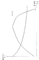
上記アサインメントメモリ40から読み出される各チャンネルの周波数ナンバデータFNは重み付けメモリ133へ送られて、重み付けデータWTが読み出され上記乗算器131へ送られ、チャンネル明け渡し(トランケート)の優先順位が重み付けされる。この重み付けメモリ133は、図12(1)に示すように各周波数ナンバデータFNに対して各重み付けデータWTが記憶されている。楽音周波数が低いほどこの重み付けデータWTは大きくなっており、低音の方がチャンネル割り当ての優先度が高くなっている。
【0059】
なお、この重み付けデータWTは図12(2)に示す特性でもよい。この特性(2)は楽音周波数が1000Hzから4000Hz当たりの中音付近の重み付けが大きくなり、低音と高音で重み付けが小さくなっている。この特性(2)は人間の等ラウドネス曲線または最低可聴曲線に沿ったものであり、人間の聴覚に合致したチャンネル割り当ての優先特性を実現できる。これは同じ周波数の各成分音を合成してチャンネル割り当てを行っている本実施例でしかできない。
【0060】
上記最低可聴曲線は人間が聴くことのできる最低の音の強さ(デシベル、レベル)(最低可聴値)の周波数(音高)に応じた特性を表し、上記等ラウドネス曲線は人間が同じ強さに聴こえる音の強さ(デシベル、レベル)の周波数(音高)に応じた特性を表す。なお、図12(2)の特性では上記等ラウドネス曲線または最低可聴曲線が逆特性にされたので、中音域の数値が大きく高音域と低音域の数値が小さくなっている。
【0061】
また、この重み付けデータWTは逆に低音の方がチャンネル明け渡し(トランケート)の頻度(可能性)が高くなってもよい。また、この重み付けメモリ133及び乗算器131は省略され、チャンネル割り当ての優先度が音楽的性質によって重み付けされなくてもよい。これにより、各チャンネルの合成成分音のレベルが小さいほどチャンネルトランケートの可能性(頻度)が高くなる。
【0062】
さらに、この重み付けメモリ133には、他の音楽的ファクタ情報が代わりに入力されてもよい。例えば上述のキーナンバデータKN、トーンナンバデータTN、パートナンバデータPN、タッチデータTC、トーンタイムデータTM、共鳴度情報などである。これにより、音域(音高)、音色、演奏分野、タッチ、発音時間、共鳴度などの音楽的性質にも応じてチャンネル割り当ての優先度が変化修正(決定制御)される。
【0063】
これにより、例えばトーン(音色)ナンバ、タッチデータ、共鳴度が大きいほど、音高(音域)、パートナンバ(MIDIチャンネルナンバ)または発音時間が小さいほど、チャンネル割り当ての優先度が高くなり、トランケートの可能性(頻度)が低くなる。なお、これらの各データが複数加算されて上記重み付けメモリ133へ送られてもよい。
【0064】
5.各最小レベル検出回路141、142及び143
図13は上記第1最小レベル検出回路141、第2最小レベル検出回路142及び第3最小レベル検出回路143を示す。上記修正エンベロープメモリ132からの修正エンベロープデータMENは、第1最小レベル検出回路141のコンパレータ151に与えられる。このコンパレータ151には、それまでに検出して第1レベルラッチ171に記憶してある最小の修正エンベロープデータMENも与えられる。この最小の修正エンベロープデータMENより上記新たな修正エンベロープデータMENが小さければ、コンパレータ151より検出信号が出力され、この信号がアンドゲート152を介してラッチ信号として、上記第1レベルラッチ171に与えられ、上記新たな修正エンベロープデータMENがストアされる。
【0065】
また、このラッチ信号は、第1チャンネルナンバラッチ181にも与えられ、上記新たな修正エンベロープデータMENに係るチャンネルナンバがストアされる。このチャンネルナンバは、上記タイミング発生部3からの上記チャンネルナンバデータCHNoである。このようにして、全チャンネル分の分割タイムが経過すると、修正エンベロープデータMENが最も小さいチャンネルのナンバが第1チャンネルナンバラッチ181にストアされ、この最も小さい修正エンベロープデータMENの値が第1レベルラッチ171にストアされる。
【0066】
さらに、上記各チャンネルの修正エンベロープデータMENの各ビットはナンドゲート群191に入力されて、全ビットが「0」で修正エンベロープデータMENのレベルが「0」ときこのナンドゲート群191より上記空きチャンネルフラグECFの信号が出力され、第1フラグラッチ192にストアされる。上記ラッチ信号は、この第1フラグラッチ192に与えられ、当該タイミングでこのストアが行われる。
【0067】
上記アンドゲート152には、図14に示すクロック信号CK0が与えられており、1つのチャンネルの分割タイムの前半でコンパレータ151で比較され、後半で上記第1チャンネルナンバラッチ181、第1レベルラッチ171及び第1フラグラッチ192へストアされる。
【0068】
図14に示すように、全チャンネル分の分割タイムが経過すると、次の全チャンネル分の分割タイムの先頭でシェアリング信号SY1がラッチ信号として、第2レベルラッチ172、第2チャンネルナンバラッチ182及び第2フラグラッチ193に与えられ、最も小さい修正エンベロープデータMENが第1レベルラッチ171から第2レベルラッチ172に転送され、第1チャンネルナンバラッチ181のチャンネルナンバが第2チャンネルナンバラッチ82に転送され、第1フラグラッチ192の空きチャンネルフラグECFが第2フラグラッチ193に転送されて、最小チャンネルメモリ134に書き込まれる。
【0069】
このシェアリング信号SY1は、上記第1レベルラッチ171にも与えられて、同ラッチ171のラッチデータが最大値「11…1」にリセットされる。上述のラッチ181、182、171、172、192及び193はR−Sタイプである。
【0070】
上記第1最小レベル検出回路141の第2チャンネルナンバラッチ182からのチャンネルナンバデータは第2最小レベル検出回路142の一致判別回路153に与えられる。この一致判別回路153には、上記第1最小レベル検出回路141の第1チャンネルナンバラッチ181に与えられているものと同じチャンネルナンバも与えられている。両データが一致したとき、一致判別回路153の出力信号はローレベルとなり、アンドゲート156が閉成される。このアンドゲート156を介して、第2最小レベル検出回路142のコンパレータ154からの比較結果信号が第1チャンネルナンバラッチ183及び第1レベルラッチ173に与えられている。
【0071】
従って、第1最小レベル検出回路141で検出された第1最小修正エンベロープデータ1MEN及び第1最小チャンネルナンバデータ1MCHが、第2最小レベル検出回路141に与えられる時には、このデータのストアが禁止される。この結果、第2最小レベル検出回路141では、2番目に小さい修正エンベロープデータMEN及びチャンネルナンバと空きチャンネルフラグECFが検出される。上記一致判別回路153は、イクスクルシブオアゲート群とオアゲートとよりなり、2つのチャンネルナンバデータの各ビットが各イクスクルシブオアゲートに与えられて、各ビットデータの相違が判別され、1つのビットでも一致しないときには、ハイレベル信号がオアゲートを介して出力される。
【0072】
この第2最小レベル検出回路142のコンパレータ154、アンドゲート155、第1チャンネルナンバラッチ183、第2チャンネルナンバラッチ184、第1レベルラッチ173、第2レベルラッチ174、ナンドゲート群194、第1フラグラッチ195及び第2フラグラッチ196の構成及び動作は、上記第1最小レベル検出回路141のコンパレータ151、アンドゲート152、第1チャンネルナンバラッチ181、第2チャンネルナンバラッチ182、第1レベルラッチ171、第2レベルラッチ172、ナンドゲート群191、第1フラグラッチ192及び第2フラグラッチ193と同じである。
【0073】
そして、第3最小レベル検出回路143のコンパレータ159、アンドゲート160、第1チャンネルナンバラッチ185、第2チャンネルナンバラッチ186、第1レベルラッチ175、第2レベルラッチ176、アンドゲート161、一致判別回路157、ナンドゲート群197、第1フラグラッチ198及び第2フラグラッチ199の構成及び動作は、上記第2最小レベル検出回路142のコンパレータ154、アンドゲート155、第1チャンネルナンバラッチ183、第2チャンネルナンバラッチ185、第1レベルラッチ173、第2レベルラッチ175、アンドゲート156、一致判別回路153、ナンドゲート群194、第1フラグラッチ195及び第2フラグラッチ196と同じである。
【0074】
上記第2最小レベル検出回路142の一致判別回路153からの信号と第3最小レベル検出回路143の一致判別回路157からの信号とは、アンドゲート158に与えられ、このアンドゲート158の出力信号が、アンドゲート161に開成信号として与えられる。このアンドゲート161を介して、第3最小レベル検出回路143のコンパレータ159からの比較結果信号が第1チャンネルナンバラッチ185及び第1レベルラッチ175に与えられている。
【0075】
従って、第1最小レベル検出回路141で検出された第1最小修正エンベロープデータ1MEN並びに第1最小チャンネルナンバ1MCH及び第2最小レベル検出回路142で検出された第2最小修正エンベロープデータ2MEN並びに第2最小チャンネルナンバ2MCHが、第3最小レベル検出回路143に与えられる時には、これらデータのセットが禁止される。この結果、第3最小レベル検出回路143では、3番目に小さい第3修正エンベロープデータ3MEN及び第3最小チャンネルナンバ3MCHと空きチャンネルフラグECFが検出されることになる。
【0076】
同様にして、第4最小レベル検出回路、第5最小レベル検出回路……が設けられ、4番目に小さい第4修正エンベロープデータ4MEN及び第4最小チャンネルナンバ4MCHと空きチャンネルフラグECF、5番目に小さい第5最小修正エンベロープデータ5MEN及び第5最小チャンネルナンバ5MCHと空きチャンネルフラグECF、…、…が検出されてもよい。
【0077】
これら空きチャンネルフラグECFは、検出された各チャンネルの楽音の減衰が達成完了されて、レベルが「0」であることを示す。したがって、このチャンネルの楽音の急速減衰(ハイリリース)は不要であり、直ちに新たな楽音が割り当てられる。
【0078】
また、チャンネルに割り当てられている楽音が消音してエンベロープレベルが「0」であれば、当該チャンネルが第1最小チャンネルナンバ1MCHとなる。割り当て楽音のエンベロープレベルが「0」のチャンネルが複数であれば、先に「0」になったチャンネルが第1最小チャンネルナンバ1MCHとなり、次に「0」になったチャンネルが第2最小チャンネルナンバ2MCHとなる。
【0079】
この検出された最小チャンネルナンバメモリ134に記憶された各最小チャンネルナンバ1MCH、2MCH及び3MCHと各空きチャンネルフラグECFは、上記コントローラ(CPU)2に送られ、新たなチャンネル割り当てに利用される。上記各第2レベルラッチ172、174及び176より出力される、検出された修正エンベロープデータMENも、最小チャンネル七メモリ134に、各最小チャンネルナンバ1MCH、2MCH、3MCHとともに記憶されてもよい。
【0080】
なお、空きチャンネルフラグECFは、エンベロープ演算データENに基づいて検出されてもよい。この場合、各最小レベル検出回路141、142及び143のナンドゲート群191、194及び197には、修正エンベロープメモリ132からの修正エンベロープデータMENではなく、エンベロープ演算メモリ48からのエンベロープ演算データENが送り込まれる。
【0081】
また、上記空きチャンネルフラグECFは、修正エンベロープデータMENが「0」ではなく、所定値未満で検出されてもよい。この場合、修正エンベロープデータMENの一部の上位ビット群のみがナンドゲート群191、194及び197に入力される。
【0082】
6.処理全体
図5はコントローラ(CPU)2によって実行される処理全体のフローチャートを示す。この処理全体は本楽音生成装置の電源オンによって開始され、電源オフまで繰り返し実行される。
【0083】
まず、プログラム/データ記憶部4の初期化など種々のイニシャライズ処理が行われ(ステップ01)、上記キーボード11またはミディインターフェース15での手動演奏または自動演奏に基づき、発音処理が行われる(ステップ03)。
【0084】
この発音処理では、空きチャンネルがサーチされ、サーチされた空きチャンネルにオンイベントに係る楽音が割り当てられる。この楽音の内容は、上記キーボード11またはミディインターフェース15からの上記演奏情報(楽音発生情報)、楽音制御情報の音楽的ファクタ情報及びこのときプログラム/データ記憶部4に既に記憶されている音楽的ファクタ情報によって決定される。
【0085】
この場合、サーチされた空きチャンネルのアサインメントメモリ40のエリアに「1」のオン/オフデータ、周波数ナンバデータFN、エンベロープスピードデータES、エンベロープタイムデータEL、「0」のエンベロープフェーズデータEFなどが書き込まれる。場合によって、トーンナンバデータTN、タッチデータTC、パートナンバデータPN、「0」のトーンタイムデータTMも書き込まれる。
【0086】
次いで、上記キーボード11またはミディインターフェース15での手動演奏または自動演奏に基づき、消音(減衰)処理が行われる(ステップ05)。この消音(減衰)処理では、オフイベント(キーオフイベント、消音イベント)に係る楽音が割り当てられているチャンネルがサーチされ当該楽音が減衰され消音される。この場合、キーオフイベントに係る楽音のエンベロープフェーズがリリースとなり、エンベロープレベルが次第に「0」になる。
【0087】
さらに、上記ミディインターフェース15またはパネルスイッチ群13の各種スイッチの操作があれば、このスイッチに対応する音楽的ファクタ情報が取り込まれ、プログラム/データ記憶部4に記憶され、音楽的ファクタ情報が変更される(ステップ06)。この後、その他の処理が実行され(ステップ07)、上記ステップ02からこのステップ07までの処理が繰り返される。
【0088】
7.発音処理(ステップ03)
図6は上記ステップ03の発音処理のフローチャートを示す。まずアサインメントメモリ40の各チャンネルエリアにハイリリースフラグHRFがセットされていれば(ステップ51)、このチャンネルにつき、最小チャンネルメモリ134の中の当該チャンネルナンバに上記空きチャンネルフラグECFが立てられているとき(ステップ52)、プログラム/データ記憶部4(RAM)に一時記憶されていた当該チャンネルのエンベロープスピードデータES、エンベロープタイムデータET、周波数ナンバデータFNなどの楽音データがアサインメントメモリ40の当該チャンネルエリアに書き込まれ(ステップ53)、このチャンネルエリアのハイリリースフラグHRFがクリアされる(ステップ54)。
【0089】
これにより、急速減衰(ハイリリース)された楽音がレベル「0」になったとき、この楽音のチャンネルが明け渡され、新たな楽音に当該チャンネルが割り当てられる。このステップ53で書き込まれる楽音データは後述するステップ57のハイリリース処理で準備される。 そして、オンイベントがあると(ステップ11)、上記成分音テーブル20に基づいてこのオンイベントに係る楽音のトーンナンバデータTNに対応する周波数ナンバ比データFNR及びエンベロープスピードデータES並びにエンベロープタイムデータETが読み出される(ステップ12)。
【0090】
次いで、このオンイベントに係る楽音のキーナンバデータKNに対応した周波数ナンバデータFNに、この読み出された各周波数ナンバ比データFNRが乗算され、各成分音の周波数ナンバデータFNが求められる(ステップ13)。そして、アサインメントメモリ40内の既に割り当てられている各成分音の周波数ナンバデータFNと、この求められた各周波数ナンバデータFNとが一致していれば(ステップ14)、このチャンネルの各フェーズのエンベロープスピードデータES及びエンベロープタイムデータETが合成エンベロープのものに書き換えられ、キーナンバデータKNが付加記憶される(ステップ15)。この合成エンベロープでは、既にこのチャンネルに割り当てられている単独成分音または合成成分音のエンベロープに、この新たな成分音のエンベロープが加算合成される。このステップ15のエンベロープ合成処理は後述する。
【0091】
また、既に割り当てられている各成分音の周波数ナンバデータFNと、求められた各周波数ナンバデータFNとが一致していなければ(ステップ14)、空きチャンネルがサーチされる(ステップ16)。この空きチャンネルのナンバは、上記最小チャンネルメモリ134に記憶されている第1最小チャンネルナンバ1MCHである。この第1最小チャンネルナンバ1MCHに空きチャンネルフラグECFが付加されていれば(ステップ56)、この第1最小チャンネルナンバ1MCHのアサインメントメモリ40のエリアに上記成分音の周波数ナンバデータFN、キーナンバデータKN及びエンベロープスピードデータES並びにエンベロープタイムデータETが書き込まれ、フェーズカウンタ50の対応チャンネルのカウンタがクリアされる(ステップ17)。
【0092】
そして、この割り当てたチャンネルの第1最小チャンネルナンバ1MCHを上記修正エンベロープメモリ132から消去する(ステップ58)。以上のエンベロープ合成処理またはチャンネル割り当て処理が他の成分音についても繰り返され(ステップ18)、その他の処理が行われる(ステップ19)。
【0093】
また、この第1最小チャンネルナンバ1MCHに空きチャンネルフラグECFが付加されておらず(ステップ56)、最も減衰している成分音がまだレベル「0」に達していなければ、当該チャンネルの成分音が急速減衰されるハイリリース処理が実行される(ステップ57)。このハイリリース処理の後、当該チャンネルに新たな成分音が割り当てられる(ステップ51〜54)。
【0094】
なお、上記ステップ16の空きチャンネルのサーチでは、第1最小チャンネルナンバ1MCHが既に消去されていれば(ステップ58)、第2最小チャンネルナンバ2MCHに応じたチャンネルに新たな成分音が割り当てられ(ステップ17)、修正エンベロープメモリ132の第2最小チャンネルナンバ2MCHが消去される(ステップ58)。
【0095】
また、第1最小チャンネルナンバ1MCH及び第2最小チャンネルナンバ2MCHが既に消去されていれば(ステップ58)、第3最小チャンネルナンバ3MCHに応じたチャンネルに新たな成分音が割り当てられ(ステップ17)、修正エンベロープメモリ132の第3最小チャンネルナンバ3MCHが消去される(ステップ58)。以下同様にして、第4最小チャンネルナンバ4MCH、第5最小チャンネルナンバ5MCH、……についても同様に処理され得る。
【0096】
さらに、上記ステップ56では、当該最小チャンネルナンバMCHに空きチャンネルフラグECFが付加されていても、アサインメント40の対応するチャンネルエリアにハイリリースフラグHRFが記憶されていれば、上記ステップ17のチャンネル割り当て処理は行われない。当該チャンネルの成分音は急速減衰中であり、次に割り当てられる成分音が予約されているからである。この場合処理は改めてステップ16へ戻る。
【0097】
また、上記ステップ58の最小チャンネルナンバMCHの消去は、上記ステップ57のハイリリース処理の後にも実行されてもよい。この場合、その後の再度同じチャンネルナンバが最小レベル検出回路141、142及び143でリストアップされ、ハイリリースの後、上記ステップ51〜54のチャンネル割り当て処理が実行される。
【0098】
8.チャンネルトランケートの例
図15は時分割チャンネルの割り当て及び明け渡し(トランケート)の例を示す。全チャンネル数が「15」で、このうち13個のチャンネルに、図15(1)に示す周波数の成分音が割り当てられており、2つのチャンネルが空いている。各周波数の成分音は図15(1)に示すレベルとなっており刻々と変化する。
【0099】
ここで図15(2)に示す成分音を持つ楽音のキーオンイベントがあると、この楽音の成分音の周波数とレベルは同図(2)のようになり、4つの成分音へのチャンネル割り当てが必要となる。
【0100】
この4つの成分音と同じ周波数の成分音にはチャンネル割り当てがなされていないと(ステップ14、18)、上記空いている2つのチャンネルに成分音が割り当てられ(ステップ16、17、58)、さらにレベルの低い2つの最小チャンネルナンバに残りの2つの成分音が割り当てられる(ステップ18、14、16、17、58)。
【0101】
こうして、図15(3)に示すように、レベルの低い2つの成分音が消去され、新たな成分音にチャンネルが明け渡し(トランケート)される。なお、新たなキーオンに係る楽音の成分音はアタック状態であって、まだレベルが低く、これから大きくなるものであり、図15(3)とは異なり、明け渡され消去される成分音のレベルが、割り当てられ発音される成分音のレベルより大きいこともある。
【0102】
9.エンベロープ合成処理(ステップ15)
図7は、上記ステップ15のエンベロープ合成処理のフローチャートを示す。まず、上記フェーズカウンタ50の当該チャンネルのフェーズカウント値とエンベロープタイムメモリ49の当該チャンネルの残存エンベロープタイムデータETがコントローラ2によって読み出され(ステップ21)、この残存エンベロープタイムデータETに残りのフェーズのエンベロープタイムデータETが順次累算され、現在時点から成分音aの各フェーズの末尾までの絶対時間が求められる(ステップ22)。
【0103】
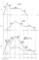
図8の例では、成分音aが発音開始し(タイミングTa0)、成分音bが発音開始し(タイミングTb0)、続いて成分音aのアタックフェーズが終了し(タイミングTa1)、この後成分音aのディケイが終了し(タイミングTa2)、成分音bのアタックが終了し(タイミングTb1)、成分音aのサスティーンが終了し(タイミングTa3)、成分音bのディケイが終了し(タイミングTb2)、成分音aのリリースが終了し(タイミングTa4)、成分音bのサスティーンが終了し(タイミングTb3)、成分音bのリリースが終了する(タイミングTb4)。
【0104】
この場合、上記残存エンベロープタイムデータETは(Ta1−Tb0)となり、上記残りのフェーズのエンベロープタイムデータETの累算値は(Ta2−Tb0)、(Ta3−Tb0)、(Ta4−Tb0)となる。各フェーズの各エンベロープタイムデータETはこれら各タイミングTa0、Ta1、Ta2、Ta3、Ta4の間の時間を示している。したがって、この残りのフェーズのエンベロープタイムデータETが累算されれば、成分音bの発音開始から各タイミングTa1、Ta2、Ta3、Ta4までの時間が求められる。
【0105】
この求められた各絶対時間(Ta2−Tb0)、(Ta3−Tb0)、(Ta4−Tb0)には、この各タイミング直前のフェーズの成分音aのエンベロープスピードデータESと成分音aを示すフラグa(「1」)も対応づけて記憶される(ステップ23)。
【0106】
次いで、成分音bについても同様にして、残存エンベロープタイムデータETに残りのフェーズのエンベロープタイムデータETが順次累算され、現在時点から成分音bの各フェーズの末尾までの絶対時間が求められる(ステップ24)。この絶対時間は同様に(Tb1−Tb0)、(Tb2−Tb0)、(Tb3−Tb0)、(Tb4−Tb0)となる。この求められた各絶対時間(Tb1−Tb0)、(Tb2−Tb0)、(Tb3−Tb0)、(Tb4−Tb0)には、この各タイミング直前のフェーズの成分音bのエンベロープスピードデータESと成分音bを示すフラグb(「0」)も対応づけて記憶される(ステップ25)。
【0107】
なお、上記タイミングTa3、Tb3は、いずれもオフ操作のタイミングであり、上記タイミングTa4、Tb4はいずれもオフ操作のタイミングによってシフトされる。したがって、上記絶対時間(Ta3−Tb0)、(Ta4−Tb0)、(Tb3−Tb0)、(Tb4−Tb0)はここでは求められない。しかし、エンベロープの形状がオフ操作によって変化しない場合には求められる。上記絶対時間(Ta3−Tb0)、(Ta4−Tb0)、(Tb3−Tb0)、(Tb4−Tb0)は、後述するように消音処理のときに求められる。このため、各成分音のサスティーンの末尾については、絶対時間は取り得る最大値とされ、エンベロープスピードデータESは「0」とされる。
【0108】
ただし、上記成分音aがリリースに入っていて、成分音bが発音開始する場合には、上記絶対時間(Ta4−Tb0)は求められる。成分音aはすでにオフ操作され、リリース終了のタイミングがはっきりしているからである。
【0109】
そして、上記ステップ22乃至25で求められた絶対時間(Ta2−Tb0)、(Ta3−Tb0)、(Ta4−Tb0)、(Tb1−Tb0)、(Tb2−Tb0)、(Tb3−Tb0)、(Tb4−Tb0)は大きい順に並べられ、対応づけられたエンベロープスピードデータESも同様に並べ変えられる(ステップ26)。これにより、図8(3)に示すような各タイミングが順番にソートされる。
【0110】
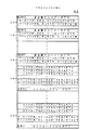
図9(1)はこのようにしてソートされた絶対時間とエンベロープスピードデータESと成分音フラグを示す。このデータ内容は、上記図8(3)の合成エンベロープ波形に対応したものとなっている。
【0111】
次いで、各絶対時間(Ta2−Tb0)、(Ta3−Tb0)、(Ta4−Tb0)、(Tb1−Tb0)、(Tb2−Tb0)、(Tb3−Tb0)、(Tb4−Tb0)から、それぞれ1つ前の絶対時間が減算される(ステップ27)。これにより、図8(3)の合成エンベロープ波形の各タイミングの間の新たなフェーズの合成エンベロープタイムデータETsが図9(2)左欄に示すように求められる。なお、先頭の合成エンベロープタイムデータETsは、上記絶対時間の先頭の(Ta2−Tb0)がそのままコピーされる。
【0112】
さらに、各絶対時間に対応したエンベロープスピードデータESには、より先の絶対時間のエンベロープスピードデータESであって、自己の成分音フラグa、bと異なるフラグを有するデータESが加算合成される(ステップ28)。これにより、成分音aのエンベロープスピードESと成分音bのエンベロープスピードESとが図8(3)の各フェーズごとに加算合成され、図8(3)の合成エンベロープ波形の各タイミングの間の新たなフェーズの合成エンベロープスピードデータESsが図9(2)右欄に示すように求められる。
【0113】
このようにして求められた合成エンベロープ波形の各フェーズの合成エンベロープタイムデータETs及び合成エンベロープスピードデータESsは、上記アサインメントメモリ40の対応するチャンネルエリアに書き込まれ、フェーズカウンタ50の対応チャンネルのカウンタがクリアされる(ステップ29)。これにより合成エンベロープの生成が開始される。この場合、合成エンベロープのオンイベント(または後述するオフイベント)の時点以降の部分が、アサインメントメモリ40に記憶され生成される。
【0114】
こうして、成分音aのエンベロープスピードデータES及びエンベロープタイムデータETは、同じ周波数の新たな成分音bが当該チャンネルに割り当てられるたびに書き換えられ、この新たな成分音bを合成したエンベロープの合成エンベロープスピードデータESs及び合成エンベロープタイムデータETsに置き換えられる。
【0115】
よって、同じ周波数の各楽音の発生量が合成され、1つのチャンネルにまとめて割り当てられることになる。また、同じ周波数の各楽音のエンベロープ波形が合成され、1つの楽音として出力されることになる。
【0116】
そして、成分音aのリリース以降のエンベロープスピードデータESとエンベロープタイムデータETとが成分音aのキーナンバデータKNに対応してアサインメントメモリ40に記憶され、成分音bのリリース以降のエンベロープスピードデータESとエンベロープタイムデータETも成分音bのキーナンバデータKNに対応してアサインメントメモリ40に記憶される(ステップ30)。このリリース以降のエンベロープスピードデータESとエンベロープタイムデータETは、オフイベント以降にエンベロープ合成処理が行われる。
【0117】
10.消音処理(ステップ05)
図10は上記ステップ05の消音処理のフローチャートを示す。まずオフイベントがあると(ステップ31)、このオフイベントに係るキーナンバデータKNと同じキーナンバデータKNが記憶されているアサインメントメモリ40のチャンネルがサーチされる(ステップ32)。
【0118】
そして、該当するチャンネルが発見されると(ステップ33)、上述したステップ15のエンベロープ合成処理と同様の処理が実行され(ステップ34)、このキーナンバデータKNと対応するエンベロープスピードデータESとエンベロープタイムデータETが当該チャンネルエリアから消去される(ステップ35)。以上のオフイベントによるエンベロープ合成処理が他の成分音についても繰り返され(ステップ36)、その他の処理が行われる(ステップ37)。
【0119】
このステップ34のエンベロープ合成処理では、上記キーナンバデータKNに対応して記憶されたリリース以降のエンベロープスピードデータESとエンベロープタイムデータETとが読み出され、同様のエンベロープ合成処理が実行される。ただし、この場合このリリースのエンベロープスピードデータESはマイナス値であるから実質的に減算される。これはディケイも同様である。なお、このステップ34のエンベロープ合成処理では、上記ステップ30のリリースのエンベロープスピードデータES及びエンベロープタイムデータETのセット処理は行われない。
【0120】
こうして、オフイベントのときにも、合成成分音a+bの合成エンベロープスピードデータESs及び合成エンベロープタイムデータETsは書き換えられ、この新たなリリースを考慮したエンベロープの合成エンベロープスピードデータESs及び合成エンベロープタイムデータETsに置き換えられる。
【0121】
よって、オフイベントのときにも、同じ周波数の各楽音の発生量が合成され、1つのチャンネルにまとめて割り当てられることになる。また、同じ周波数の各楽音のエンベロープ波形が合成され、1つの楽音として出力されることになる。
【0122】
11.ハイリリース処理(ステップ57)
図16は上記ステップ57のハイリリース処理のフローチャートを示す。当該チャンネルのエンベロープ演算データENをEN演算メモリ48から取り込み(ステップ61)、このエンベロープが「0」になるまでの最短時間ETrつまりハイリリースのエンベロープタイムETrが以下の演算で求められる(ステップ62)。
【0123】
ETr=(ET/ESmin)
ここでETは上記現在のエンベロープ演算データENであり、ESminは取り得る最小のエンベロープスピードデータであって、最大傾斜の減衰を実現する。
【0124】
次いで、この最小エンベロープスピードデータESminとハイリリースエンベロープタイムETrとが、アサインメントメモリ40の当該チャンネルエリアに書き込まれるとともに(ステップ63)、さらにハイリリースフラグHRFも書き込まれ(ステップ64)、他のエンベロープスピードデータES及びエンベロープタイムデータET、エンベロープフェーズデータEFが消去される(ステップ65)。これにより、図17の「ESmin」に示すように、チャンネルを明け渡す先の楽音(成分音)のエンベロープスピードがESnからESminに切り替えられ、当該楽音(成分音)が急速に減衰される。このとき、後の楽音(成分音)はキーオンがあっても発音開始されない。
【0125】
そして、上記ハイリリースエンベロープタイムETrの遅れを取り戻すため、最大エンベロープスピードデータESmaxとこれによって追いつくハイアタックのエンベロープタイムデータETaが以下の演算で求められる(ステップ71)。
【0126】
ETa=(ES1×ETr)/(ESmax−ES1)
ここでETrは上記ハイリリースのエンベロープタイムであり、ES1はこの新たな楽音(成分音)のアタックのエンベロープスピードであり、ESmaxは取り得る最大のエンベロープスピードデータであって、最大傾斜のアタックを実現する。
【0127】
次いで、この最大エンベロープスピードデータESmaxとハイアタックエンベロープタイムETaとが、プログラム/データ記憶部4(RAM)に一時的に書き込まれる(ステップ72)。これにより、図17の「ESmax」で示すハイアタックのエンベロープ部分のデータが作成される。
【0128】
そして、エンベロープスピードデータES1とエンベロープタイム(ET1−ETr−ETa)とが、プログラム/データ記憶部4(RAM)に一時的に書き込まれる(ステップ73)。これにより、図17の新たな成分音の残りのアタックエンベロープ部分のデータが作成される。
【0129】
次いで、これ以降のエンベロープスピードデータES及びエンベロープタイムデータETが同様に書き込まれ(ステップ74)、上記ステップ13で求められた周波数ナンバデータFNも同様に書き込まれ(ステップ75)、さらに当該チャンネルナンバCHNoも同様に書き込まれる(ステップ76)。このチャンネルナンバCHNoは上記ステップ53の書き込みで、チャンネルの対応のチェックに利用される。
【0130】
こうして新たな成分音の修正されたエンベロープスピードデータ及びエンベロープタイムデータが作成され一時記憶される。この一時記憶されたエンベロープデータは、上記ステップ53でアサインメントメモリ40に書き込まれる。
【0131】
なお、上記ステップ72及び73で求められる2つのエンベロープスピードデータ及び2つのエンベロープタイムデータは、以下の1つのエンベロープスピードデータ及び1つのエンベロープタイムデータで代用できる。
【0132】
ES=ES1×ET1/(ET1−ETr)
ET=ET1−ETr
ここで、ET1はこの新たな楽音(成分音)のアタックのエンベロープタイムであり、ES1はこの新たな楽音(成分音)のアタックのエンベロープスピードであり、ETrは上記ハイリリースのエンベロープタイムである。これにより、新たな成分音のアタックは図17の点線に示す状態となる。
【0133】
12.トーンタイムデータTM及び同時発音数の処理
図11はコントローラ2によって一定周期ごとに実行されるインタラプト処理のフローチャートを示す。この処理で上記トーンタイムデータTMのインクリメント及び同時発音数のカウントが行われる。
【0134】
この処理では、上記アサインメントメモリ40の各チャンネルエリアにつき(ステップ41、46、47)、オン/オフデータが「1」で楽音が発音中のものについて(ステップ43)、そのトーンタイムデータTMが「+1」される(ステップ44)。
【0135】
また、同じくアサインメントメモリ40の各チャンネルエリアにつき(ステップ41、46、47)、いったん同時発音数データがクリアされた後(ステップ42)、オン/オフデータが「1」で楽音が発音中のものがカウント(ステップ43)、同時発音数が順次「+1」される(ステップ45)。このカウントされた同時発音数はプログラム/データ記憶部4に記憶される。
【0136】
そして、その他の周期的な処理が行われる(ステップ48)。こうして、各チャンネルの楽音の発音経過時間がカウントされ記憶され上記発音時間情報として利用され、またそのときどきの全チャンネルの発音中の楽音の数がカウントされ記憶され上記同時発音数情報として利用される。
【0137】
本発明は上記実施例に限定されず、本発明の趣旨を逸脱しない範囲で種々変更可能である。例えば、波形メモリ42に記憶される楽音波形データMWはサイン波以外の複雑な波形でもよいし、音色、音高(音域)、タッチ、パート、発音時間ごとに異なる波形が記憶され切り替え選択されてもよい。このような複雑な形状の波形は上記各成分音の楽音波形として読み出され出力される。
【0138】
また、各チャンネルに割り当てられる楽音は成分音以外の1つの独立した楽音であってもよい。この場合、同じチャンネルに割り当てられる楽音の波形は同じ波形形状であり、同じ音高(周波数)である。このような場合でも同様にエンベロープの合成または発生量の合成を行うことができる。
【0139】
さらに、合成されるのはエンベロープ以外の楽音波形データMWの振幅でもよい。この場合上記ステップ15、34で合成されるのは、振幅決定因子例えばタッチデータTCなどである。そして、アサインメントメモリ40の各チャンネルのタッチデータTCは、上記オンイベント及びオフイベントごとに相加され、この相加されたタッチデータTCはアサインメントメモリ40から上記乗算器43へ送られ、楽音波形データMWに乗算される。なお、この相加されたタッチデータTCは、当該チャンネルの各エンベロープスピードデータESに乗算されてもよい。この乗算されたエンベロープスピードデータESを使って上記ステップ15、34のエンベロープ合成が行われる。
【0140】
また、上記チャンネルは時分割処理によって形成されたが、このチャンネルと同じ数の楽音信号発生部5が設けられ、各楽音信号発生部5〜の楽音波形データMWが加算器で加算合成されてもよい。
【0141】
さらに、上記エンベロープデータは、エンベロープスピードデータESとエンベロープレベルデータEL、またはエンベロープレベルデータELとエンベロープタイムデータETとで代用されてもよい。この場合、隣り合う2つのエンベロープレベルデータELの差がエンベロープスピードデータESで除算されて上記エンベロープタイムデータETが求められる。また、隣り合う2つのエンベロープレベルデータELの差がエンベロープタイムデータETで除算されて上記エンベロープスピードデータESが求められる。
【0142】
また、上記チャンネルトランケートでは、アタック状態またはエンベロープスピードデータがプラスである成分音の重み付けデータWTは格段に大きくされてもよい。この場合、上記アサインメントメモリ40から読み出されたエンベロープフェーズデータEFが重み付けメモリ133で変換され、エンベロープフェーズデータEFが所定値未満ならば、大きい値に変換されて上記乗算器131へ送られ、エンベロープフェーズデータEFが所定値を越えれば、小さい値に変換されて上記乗算器131へ送られる。これにより、エンベロープフェーズの音楽的性質によってチャンネル割り当ての優先度が変化修正(決定制御)される。
【0143】
さらに、上記チャンネルトランケートでは、あるレベル以上の成分音を有するチャンネルは明け渡されなくてもよい。この場合、上記ステップ16で各最小チャンネルナンバMCHに応じたチャンネルの修正エンベロープデータMENが修正エンベロープメモリ132より読み出され、所定レベル未満ならばステップ17及び58のチャンネルトランケートが実行される。これにより、楽音レベルの音楽的性質によってチャンネル割り当ての優先度が変化修正(決定制御)される。
【0144】
また、上記チャンネルトランケートは、1つのチャンネルに合成して割り当てられている成分音の数が多いほど、明け渡し(トランケート)の可能性が低くなってもよい。この場合、上記ステップ13の後またはステップ16などで、アサインメントメモリ40の各チャンネルエリアに記憶されているキーナンバデータKNの数によって決定される重み付けデータWTが各修正エンベロープデータMENに乗算される。
【0145】
この重み付けデータは、例えば1チャンネル当たりの上記キーナンバデータKNの数が「1」ならば「0.7」、「2」ならば「0.8」、「3」ならば「0.9」、「4」以上ならば「1.0」である。この重み付けデータWTによって修正された修正エンベロープデータMENに基づいて上記第1最小レベル検出回路141、第2最小レベル検出回路142、第3最小レベル検出回路143、…、…、でレベルの低い成分音に係るチャンネルナンバがサーチされる。これにより、各時分割チャンネルに割り当てられている成分音の数という音楽的性質によってチャンネル割り当ての優先度が変化修正(決定制御)される。
【0146】
さらに、上記新たに割り当てられる楽音の周波数と上記急速に減衰されチャンネルを明け渡す楽音の周波数とは異なっていたが、同じでもよい。この場合、上記ステップ14及び15の処理は省略される。これにより、同じ周波数の成分音同志はエンベロープ合成されず、先の成分音が急速減衰されたのち、新たな同じ周波数の成分音にチャンネルが明け渡されアタックが開始される。
【0147】
また、本発明は電子楽器またはコンピュータなどにおいて実施され得る。上記各図の回路の機能はソフトウエア(フローチャート)によって実施されても良いし、上記各図のフローチャートの機能はハードウエア(回路)によって実施されてもよい。各請求項記載の発明は、当該発明をコンピュータに実行させるコンピュータプログラムを記憶した媒体、コンピュータプログラムの通信装置(方法)、楽音発生装置(方法)、楽音制御装置(方法)としても実現可能である。
【0148】
本発明の実施態様は以下の通りである。 [1]同時に発生される複数の楽音がそれぞれ割り当てられる複数のチャンネルにつき、 この同時に発生される複数の楽音のうち、同じ周波数の楽音を判別し、 この判別された同じ周波数の楽音の発生量を合成して、1つのチャンネルにまとめて割り当てることを特徴とする楽音のチャンネル割り当て装置。
【0149】
[2]同時に発生される複数の楽音がそれぞれ割り当てられる複数のチャンネルにつき、 この同時に発生される複数の楽音のうち、同じ周波数の楽音を判別させ、 この判別された同じ周波数の楽音の発生量を合成して、1つのチャンネルにまとめて割り当てさせることを特徴とする楽音のチャンネル割り当て方法。
【0150】
[3]同時に発生される複数の楽音のうち、同じ周波数の楽音を判別し、 この判別された同じ周波数の各楽音のエンベロープ波形を合成して1つの楽音として出力することを特徴とする楽音のエンベロープ制御装置。
【0151】
[4]同時に発生される複数の楽音のうち、同じ周波数の楽音を判別させ、 この判別された同じ周波数の各楽音のエンベロープ波形を合成して1つの楽音として出力させることを特徴とする楽音のエンベロープ制御方法。
【0152】
[5]上記同時に発生される複数の楽音は、1つの楽音を構成する成分音であり、 この同時に発生される複数の楽音は、同じ波形または異なる波形の楽音であり、 新たな楽音が発生されるときまたは発生されている楽音が消滅されるとき、この楽音またはこの楽音の成分音の同じ周波数の各エンベロープ発生量につき、合成したエンベロープ発生量の各エンベロープレベル、エンベロープタイム及びエンベロープスピードのいずれか2つを演算して、この演算したエンベロープレベル、エンベロープタイム及びエンベロープスピードのいずれか2つに基づいて、上記周波数の楽音またはこの楽音の成分音の合成エンベロープを1つのチャンネルで生成することを特徴とする請求項1、2、3または4記載の楽音のチャンネル割り当て装置、楽音のチャンネル割り当て方法、楽音のエンベロープ制御装置または楽音のエンベロープ制御方法。
【0153】
[6]同時に発生される複数の楽音がそれぞれ割り当てられる複数のチャンネルにつき、 この同時に発生される複数の楽音のうち、同じ周波数の楽音を判別する手段と、 この判別された同じ周波数の楽音の発生量を合成して、1つのチャンネルにまとめて割り当てる手段と、 このようにして各チャンネルに割り当てられている各楽音につき、チャンネル明け渡しの優先順位を決定する手段と、この決定された優先順位に基づいてチャンネルを選び出し、このチャンネルに新たな楽音を割り当てる手段とを備えたことを特徴とする楽音のチャンネル割り当て装置。
【0154】
[7]同時に発生される複数の楽音がそれぞれ割り当てられる複数のチャンネルにつき、 この同時に発生される複数の楽音のうち、同じ周波数の楽音を判別させ、 この判別された同じ周波数の楽音の発生量を合成して、1つのチャンネルにまとめて割り当てさせ、 このようにして各チャンネルに割り当てられている各楽音につき、チャンネル明け渡しの優先順位を決定させ、 この決定された優先順位に基づいてチャンネルを選び出させ、このチャンネルに新たな楽音を割り当てさせることを特徴とする楽音のチャンネル割り当て方法。
【0155】
[8]上記同時に発生される複数の楽音は、1つの楽音を構成する成分音であり、 複数の楽音のそれぞれの成分音につき同じ周波数の成分音を判別し、各成分音を同じ周波数ごとに合成して各チャンネルに割り当て、 この同時に発生される複数の楽音は、同じ波形または異なる波形の楽音であり、 上記チャンネル明け渡しの優先順位は、各チャンネルに割り当てられている楽音のレベル、当該楽音の音楽的性質、人間の等ラウドネス特性または人間の最低可聴特性に基づいて決定されることを特徴とする請求項6記載の楽音のチャンネル割り当て装置または請求項7記載の楽音のチャンネル割り当て方法。
【0156】
出願当初の特許請求の範囲は以下のとおりであった。
[9]同時に発生される複数の楽音がそれぞれ割り当てられる複数のチャンネルにつき、 この同時に発生される複数の楽音のうち、同じ周波数の楽音を判別する手段と、 この判別された同じ周波数の楽音の発生量を合成して、1つのチャンネルにまとめて割り当てる手段と、 このようにして楽音が割り当てられている上記複数のチャンネルから1つのチャンネルを選び出し、このチャンネルに割り当てられている楽音を急速に減衰する手段と、 この急速な減衰が達成されたとき、当該チャンネルに新たな楽音を割り当てる手段とを備えたことを特徴とする楽音のチャンネル割り当て装置。
[10]同時に発生される複数の楽音がそれぞれ割り当てられる複数のチャンネルにつき、 この同時に発生される複数の楽音のうち、同じ周波数の楽音を判別させ、 この判別された同じ周波数の楽音の発生量を合成して、1つのチャンネルにまとめて割り当てさせ、 このようにして楽音が割り当てられている上記複数のチャンネルから1つのチャンネルを選び出しさせ、このチャンネルに割り当てられている楽音を急速に減衰させ、 この急速な減衰が達成されたとき、当該チャンネルに新たな楽音を割り当てさせることを特徴とする楽音のチャンネル割り当て方法。
[11]上記同時に発生される複数の楽音は、1つの楽音を構成する成分音であり、 複数の楽音のそれぞれの成分音につき同じ周波数の成分音を判別し、各成分音を同じ周波数ごとに合成して各チャンネルに割り当て、 この同時に発生される複数の楽音は、同じ波形または異なる波形の楽音であり、 上記選び出されるチャンネルは、決定されたチャンネル明け渡しの優先順位に基づいて選び出され、 このチャンネル明け渡しの優先順位は、各チャンネルに割り当てられている楽音のレベル、当該楽音の音楽的性質、人間の等ラウドネス特性または人間の最低可聴特性に基づいて決定され、 上記急速な減衰は、当該楽音のエンベロープの変化のスピードを大きくし、 上記急速な減衰が達成されたときは、当該楽音のレベルが「0」または所定値未満になったときであり、 上記新たに割り当てられる楽音の周波数と上記急速に減衰されチャンネルを明け渡す楽音の周波数とは異なるまたは同じであることを特徴とする請求項9記載の楽音のチャンネル割り当て装置または請求項10記載の楽音のチャンネル割り当て方法。
【発明の効果】
以上詳述したように、本発明では、同時に発生される複数の楽音のうち、同じ周波数の楽音を判別し、この判別された同じ周波数の楽音の発生量を合成して、1つのチャンネルにまとめて割り当て、各チャンネルに割り当てられている各楽音につき、チャンネル明け渡しの優先順位を決定し、この決定された優先順位に基づいてチャンネルを選び出し、このチャンネルに割り当てられている楽音を急速に減衰し、この急速な減衰が達成されたとき、当該チャンネルに新たな楽音を割り当てるようにした。
【0157】
したがって、使用するチャンネルの数を減らしてチャンネルの有効利用を図ることができ、空きチャンネルがないとき新たな楽音にチャンネルを明け渡して(トランケート)して、新たな楽音に確実にチャンネルを割り当てることができるし、上記急速な減衰によって新たな楽音へのチャンネル割り当てを迅速に行うことができる等の効果を奏する。
【図面の簡単な説明】
【図1】楽音制御装置の全体回路を示す。
【図2】成分音テーブル20を示す。
【図3】アサインメントメモリ40を示す。
【図4】楽音信号発生部5を示す。
【図5】処理全体のフローチャートを示す。
【図6】発音処理(ステップ03)のフローチャートを示す。
【図7】エンベロープ合成処理(ステップ15)のフローチャートを示す。
【図8】同じ周波数の成分音aと成分音bとのエンベロープ合成の波形の例を示す。
【図9】同じ周波数の成分音aと成分音bとのエンベロープ合成のデータの例を示す。
【図10】消音処理(ステップ05)のフローチャートを示す。
【図11】インタラプト処理のフローチャートを示す。
【図12】重み付けメモリ133に記憶された重み付けデータWTの内容を示す。
【図13】第1最小レベル検出回路141、第2最小レベル検出回路142及び第3最小レベル検出回路143の回路図を示す。
【図14】図13の回路の各部の信号のタイムチャートを示す。
【図15】成分音の割り当てられている各時分割チャンネルのトランケートの例を示す。
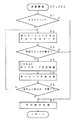
【図16】ハイリリース処理(ステップ57)のフローチャートを示す。
【図17】ハイリリースの時のエンベロープの変化を示す。
【符号の説明】
2…コントローラ(CPU)、3…タイミング発生部、4…プログラム/データ記憶部、5…楽音信号発生部、6…サウンドシステム、7…情報記憶部、11…キーボード、13…パネルスイッチ群、15…ミディインターフェース、20…成分音テーブル、40…アサインメントメモリ、41…波形読み出し部、42…波形メモリ、47…セレクタ、48…エンベロープ演算メモリ、49…エンベロープタイムメモリ、50…フェーズカウンタ、46,51…加算器、52…ナンドゲート群、131…乗算器、132…修正エンベロープメモリ、133…重み付けメモリ、134…最小チャンネルメモリ、141…第1最小レベル検出回路、142…第2最小レベル検出回路、143…第3最小レベル検出回路。[0001]
BACKGROUND OF THE INVENTION
The present invention relates to a musical sound channel assignment apparatus or a musical sound channel assignment method, and more particularly to control of synthesis of musical sounds having the same frequency.
[0002]
[Prior art]
Conventionally, in an electronic musical instrument channel assignment device, a number of musical sound generation channels that are not more than the number of musical sounds that can be generated simultaneously are configured by time-sharing processing. Assigned to an empty channel, thereby generating a musical sound.
[0003]
The musical sound assigned to each channel depends on the operation of each key on the keyboard, and the pitch (frequency) is different. The waveform of this tone is the same or different. If the tone waveform is different, the tone will be different.
[0004]
[Problems to be solved by the invention]
However, in some cases, a plurality of musical sounds assigned to each channel have the same pitch (frequency), and it is useless to assign different channels to such a musical tone having the same frequency. In addition, some of the envelope musical sounds generated individually have the same pitch (frequency) in some cases, and it was useless to add separate envelopes to such musical sounds of the same frequency.
[0005]
[Means for Solving the Problems]
In order to achieve the above object, the present invention discriminates musical tones having the same frequency among a plurality of musical tones generated at the same time, synthesizes the generated amounts of musical tones having the same frequency, and combines them into one channel. For each tone assigned to each channel, determine the priority for channel surrender, select a channel based on this determined priority, rapidly attenuate the tone assigned to this channel, When this rapid decay was achieved, a new tone was assigned to the channel.
[0006]
As a result, the number of channels to be used can be reduced for effective use of channels, and when there are no free channels, channels are transferred to new musical sounds (truncated), and channels are allocated to new musical sounds without fail. The channel can be quickly assigned to a new musical tone by the rapid attenuation.
[0007]
DETAILED DESCRIPTION OF THE INVENTION
1. Overall circuit
FIG. 1 shows an entire circuit of a musical tone control apparatus or an electronic musical instrument. Each key of the
[0008]
Each key of the
[0009]
The
[0010]
Each switch of the
[0011]
The
[0012]
The
[0013]
The performance information (musical tone generation information) is musical factor information, such as pitch (frequency range) information (pitch determinant), pronunciation time information, performance field information, pronunciation number information, resonance information, etc. is there. The pronunciation time information indicates the elapsed time from the start of tone generation. The performance field information indicates performance part information, musical sound part information, musical instrument part information, etc., and corresponds to, for example, melody, accompaniment, chord, bass, rhythm, MIDI, etc., or upper keyboard, lower keyboard, foot keyboard, solo keyboard , MIDI, etc.
[0014]
The pitch information is captured as key number data KN. The key number data KN is composed of octave data (sound range data) and pitch name data. The performance field information is taken in as part number data PN, and this part number data PN is data for identifying each performance area, and is set according to which performance area the musical sound subjected to sound generation is from.
[0015]
The pronunciation time information is taken in as tone time data TM and is obtained by a flowchart described later, based on time count data from a key-on event, or substituted in an envelope phase. This sounding time information is shown in detail in Japanese Patent Application No. 6-219324 and drawings as elapsed time information from the start of sounding.
[0016]
The number-of-sounding information indicates the number of musical sounds that are simultaneously generated. For example, this number is based on the number of musical sounds whose on / off data in the
[0017]
The resonance degree information indicates the degree of resonance between one musical sound that is sounded at the same time and another musical sound. If the pitch frequency of one musical tone and the pitch frequency of the other musical tone are small integer ratios such as 1: 2, 2: 3, 3: 4, 4: 5, 5: 6, the resonance information The value is large, and the value of the resonance degree information is small if the integer multiple ratio is large such as 9: 8, 15: 8, 15:16, 45:32, 64:45. This resonance degree information is read from the resonance correlation table 53 or the resonance ratio table 54 in FIG. 7 of Japanese Patent Application No. 1-314818.
[0018]
Further, the
[0019]
Music control information is generated from the various switches, and the music control information is information for controlling the generated music and is musical factor information. Tone information (tone determination factor), touch information (pronunciation) Speed (intensity of instruction operation), sound number information, resonance information, effect information, rhythm information, sound image (stereo) information, quantize information, modulation information, tempo information, volume information, envelope information, and the like. The musical factor information is also merged with the performance information (musical sound information) and input from the various switches, and is merged with the automatic performance information or merged with the performance information transmitted / received through the interface.
[0020]
The tone information corresponds to the type of instrument (sounding medium / sounding means) of a keyboard instrument (piano, etc.), a wind instrument (flute, etc.), a stringed instrument (violin, etc.), and a percussion instrument (drum, etc.). Captured as TN. The envelope information includes an envelope level EL, an envelope time ET, an envelope phase EF, and the like.
[0021]
Such musical factor information is sent to the
[0022]
The program / data storage unit 4 (internal storage medium / means) includes a storage device such as ROM or writable RAM, flash memory, or EEPROM, and is stored in the information storage unit 7 (external storage medium / means) such as an optical disk or magnetic disk. The stored computer program is copied and stored (installed / transferred). The program /
[0023]
This installation (transfer / copy) is automatically executed when the
[0024]
Note that another operating system, a system program (OS), and other programs may be stored in advance in the apparatus, and the program may be executed together with these OS and other programs. When this program is installed in the apparatus (computer main body) and executed, it is only necessary to execute the processing / function described in the claims together with another program or alone.
[0025]
Further, a part or all of this program is stored and executed in one or more other devices other than this device, and data to be processed / already processed through communication means between this device and another device. The present invention may be executed as the entire apparatus and the separate apparatus.
[0026]
The program /
[0027]
In the
[0028]
From the
[0029]
2. Component sound table 20
FIG. 2 shows a component sound table 20 in the program /
[0030]
The frequency number ratio data FNR indicates the ratio of the frequency of each component sound to the fundamental frequency according to the pitch. The specified pitch frequency is multiplied by the frequency number ratio data FNR to obtain the frequency of each component sound. Since the frequency number ratio data FNR of the fundamental frequency is “1”, it may be omitted.
[0031]
The envelope data indicates an envelope for each component sound. Each envelope data is composed of envelope speed data ES and envelope time data ET for each envelope phase. Envelope speed data ES indicates a step value of calculation per cycle of envelope digital calculation. The envelope time data ET indicates the envelope calculation time (generation time, sound generation time) for each phase, that is, the number of calculations for each phase of the digital calculation. The amplitude of the envelope waveform calculated from the envelope speed data ES and the envelope time data ET indicates the amount of each component sound (each musical sound) generated.
[0032]
The number of component sounds is plural for one timbre, but may be one in some cases. This component sound is synthesized and output for each musical tone. This composition ratio changes according to the envelope data. If the envelope calculation level based on the envelope data is “0”, the ratio of the component sound is “0”. One channel is assigned to each of the component sounds, the envelopes are individually controlled, synthesized, and output.
[0033]
3.
FIG. 3 shows the
[0034]
Each channel memory area stores frequency number data FN, key number data KN and high release flag HRF of the component sound to which the channel is assigned, the envelope speed data ES, envelope time data ET, and envelope phase data EF. . In some cases, tone number data TN, touch data TC, tone time data TM, part number data PN, the resonance information, on / off data, and the like are also stored.
[0035]
The on / off data indicates whether a musical sound (component sound) to be assigned and sounded is key-on or sounding (“1”), key-off or sound-deadening (“0”). The frequency number data FN indicates the frequency value of the component sound assigned and sounded, converted from the key number data KN, and further multiplied by the frequency number ratio data FNR. The program /
[0036]
The high release flag HRF indicates that the tone of the channel has been determined to give up the channel to a new tone, and the currently assigned tone is rapidly attenuated. This high release flag HRF is set when channel surrender is determined, and is cleared when the tone becomes level “0” or below a predetermined level.
[0037]
The envelope speed data ES and the envelope time data ET are as described above. The envelope speed data ES and the envelope time data ET are rewritten every time a new component sound having the same frequency is assigned to the channel, and the envelope speed data ES and envelope time data ET of the envelope obtained by synthesizing the new component sound. Replaced.
[0038]
The envelope phase data EF indicates each part of the envelope before or after the synthesis of (1), (2), and (3) in FIG. The count value from the phase counter 50 is taken in and stored in the
[0039]
The key number data KN indicates the pitch (frequency) of the musical sound assigned and pronounced, and is determined according to the pitch information. The key number data KN is stored for all component sounds constituting one musical sound, and each time the component sound is assigned to a channel and synthesized, the key number data KN is stored in the
[0040]
Corresponding to each key number data KN, envelope speed data ES and envelope time data ET for releasing the envelope of the component sound are stored. If there are a plurality of envelope speed data ES and envelope time data ET of this release in one component sound, all of the plurality are stored.
[0041]
The tone number data TN indicates the tone color of the assigned tone to be generated and is determined according to the tone color information. If the tone number data TN is different, the tone color is different, and the tone waveform of the tone is also different. The touch data TC indicates the speed or strength of the sound generation operation, is obtained based on the operation of the step switch, or is determined according to the touch information. The part number data PN indicates each performance area as described above, and is set according to which performance area the musical sound subjected to sound generation is from. The tone time data TM indicates the elapsed time from the key-on event.
[0042]
Each data in each channel memory area is written at an on timing and / or an off timing, and is rewritten or read at each channel timing, and processed by the
[0043]
A method of assigning or truncating each musical sound to a plurality of musical sound generating systems for generating a plurality of musical sounds (component sounds) in parallel, that is, a channel formed by the time division processing, is disclosed in, for example, Japanese Patent Application No. 1-442298. No. 1, Japanese Patent Application No. 1-305818, Japanese Patent Application No. 1-312175, Japanese Patent Application No. 2-2089178, Japanese Patent Application No. 2-409777, and Japanese Patent Application No. 2-409578 are used.
[0044]
4).
FIG. 4 shows the
[0045]
This musical sound waveform data MW is only one kind of sine wave. Accordingly, a plurality of sine waves having different frequencies for one musical sound are synthesized with harmonics and output. Therefore, if the amplitude or frequency of each sine wave changes, the waveform of the musical tone to be synthesized also changes and the tone color also changes. The sine wave is not stored in the memory, but may be converted from the tone time data TM or the time count data TI by trigonometric function calculation.
[0046]
The musical sound waveform data MW may be a complex waveform other than a sine wave, or a different waveform may be stored and selected for each tone color, part, pitch (tone range), touch, and sounding time. In this case, tone number data TN, part number data PN, touch data TC, etc. are sent to the
[0047]
The envelope speed data ES of each channel of the
[0048]
The
[0049]
The envelope time data ET of each channel of the
[0050]
This phase end signal is input to the phase counter 50 and incremented, that is, +1. In this phase counter 50, the phase of the envelope of each channel is counted. The phase counter 50 is provided with a counter corresponding to the number of time-division channels, only the counter designated by the channel number data CHNo is enabled, and only the designated counter is incremented or reset.
[0051]
Only the counter designated by the channel number data CHNo is reset (cleared) by the
[0052]
The envelope phase data EF of the phase counter 50 is sent as address data to the
[0053]
The phase end signal is sent to the
[0054]
The envelope calculation data EN of each channel from the
[0055]
The weighted and corrected corrected envelope data MEN are compared by the first minimum level detection circuit 141, the second minimum level detection circuit 142, and the third minimum level detection circuit 143. The channel number with the second lowest music level is detected. The detected first minimum channel number 1MCH, second minimum channel number 2MCH, and third minimum channel number 3MCH are stored in the minimum channel number memory 134. The minimum channel numbers 1MCH, 2MCH, and 3MCH indicate the priority of channel surrender (truncation).
[0056]
In the first minimum level detection circuit 141, the second minimum level detection circuit 142, and the third minimum level detection circuit 143, a channel having the modified envelope data MEN of “0” is also detected, and this detection data is used as an empty channel flag ECF. Are stored in the minimum channel number memory 134 together with the channel numbers 1MCH, 2MCH, and 3MCH.
[0057]
The minimum channel number memory 134 is composed of three latches, and the three minimum channel numbers 1MCH, 2MCH and 3MCH and three free channel flags ECF from the three minimum level detection circuits 141, 142 and 143 are stored in the three latches. Each is stored. The minimum channel number memory 134 and the modified envelope memory 132 are written in the first half of one time division channel time and read in the second half.
[0058]
The frequency number data FN of each channel read out from the
[0059]
The weighting data WT may have the characteristics shown in FIG. In this characteristic (2), the weighting in the vicinity of the middle tone per 1000 to 4000 Hz of the musical tone frequency is increased, and the weighting is reduced between the low tone and the high tone. This characteristic (2) is along a human equal loudness curve or the lowest audible curve, and can realize a priority characteristic of channel assignment that matches human hearing. This can be done only in the present embodiment in which component sounds having the same frequency are synthesized and channel assignment is performed.
[0060]
The minimum audible curve represents the characteristics of the lowest sound intensity (decibel, level) (minimum audible value) that humans can hear, and the equal loudness curve is the same intensity for humans. Represents the characteristics corresponding to the frequency (pitch) of the sound intensity (decibel, level) heard. In the characteristic shown in FIG. 12 (2), since the equal loudness curve or the lowest audible curve is reversed, the numerical value of the middle range is large and the numerical value of the high range and the low range are small.
[0061]
On the contrary, the weighted data WT may have a higher frequency (possibility) of channel surrender (truncation) in the case of a low tone. Further, the weighting memory 133 and the
[0062]
Further, other musical factor information may be input to the weighting memory 133 instead. For example, the above-described key number data KN, tone number data TN, part number data PN, touch data TC, tone time data TM, resonance degree information, and the like. As a result, the channel assignment priority is modified (decision controlled) in accordance with musical properties such as tone range (pitch), tone color, performance field, touch, sound generation time, and resonance.
[0063]
Thus, for example, the higher the tone number (tone color), touch data, and resonance level, the higher the pitch (range), the part number (MIDI channel number), or the shorter the sounding time, the higher the priority of channel assignment and the truncation. The possibility (frequency) becomes low. A plurality of these data may be added and sent to the weighting memory 133.
[0064]
5. Each minimum level detection circuit 141, 142 and 143
FIG. 13 shows the first minimum level detection circuit 141, the second minimum level detection circuit 142, and the third minimum level detection circuit 143. The modified envelope data MEN from the modified envelope memory 132 is given to the
[0065]
The latch signal is also supplied to the first
[0066]
Further, each bit of the modified envelope data MEN of each channel is input to the
[0067]
The AND
[0068]
As shown in FIG. 14, when the division time for all channels elapses, the sharing signal SY1 is used as a latch signal at the head of the division time for the next all channels, and the second level latch 172, the second
[0069]
The sharing signal SY1 is also supplied to the first level latch 171 and the latch data of the latch 171 is reset to the maximum value “11... 1”. The above-mentioned
[0070]
The channel number data from the second
[0071]
Accordingly, when the first minimum modified envelope data 1MEN and the first minimum channel number data 1MCH detected by the first minimum level detection circuit 141 are given to the second minimum level detection circuit 141, the storage of this data is prohibited. . As a result, the second minimum level detection circuit 141 detects the second smallest modified envelope data MEN, the channel number, and the empty channel flag ECF. The
[0072]
The
[0073]
The
[0074]
The signal from the
[0075]
Accordingly, the first minimum modified envelope data 1MEN detected by the first minimum level detection circuit 141, the second minimum corrected envelope data 2MEN detected by the first minimum channel number 1MCH and the second minimum level detection circuit 142, and the second minimum. When the channel number 2MCH is supplied to the third minimum level detection circuit 143, the setting of these data is prohibited. As a result, the third smallest level detection circuit 143 detects the third smallest third modified envelope data 3MEN, the third smallest channel number 3MCH, and the empty channel flag ECF.
[0076]
Similarly, a fourth minimum level detection circuit, a fifth minimum level detection circuit,... Are provided, and the fourth smallest modified fourth envelope data 4MEN and fourth minimum channel number 4MCH and the empty channel flag ECF are fifth smallest. The fifth minimum modified envelope data 5MEN, the fifth minimum channel number 5MCH, and the empty channel flag ECF,... May be detected.
[0077]
These vacant channel flags ECF indicate that the attenuation of the tone of each detected channel is completed and the level is “0”. Therefore, rapid decay (high release) of the musical sound of this channel is unnecessary, and a new musical sound is immediately assigned.
[0078]
If the musical sound assigned to the channel is muted and the envelope level is “0”, the channel becomes the first minimum channel number 1MCH. If there are a plurality of channels whose envelope level of the assigned musical sound is “0”, the channel that has become “0” first becomes the first minimum channel number 1MCH, and the channel that has subsequently become “0” becomes the second minimum channel number. 2MCH.
[0079]
The minimum channel numbers 1MCH, 2MCH and 3MCH and the free channel flags ECF stored in the detected minimum channel number memory 134 are sent to the controller (CPU) 2 and used for new channel allocation. The detected corrected envelope data MEN output from each of the second level latches 172, 174, and 176 may be stored in the minimum channel seven memory 134 together with the minimum channel numbers 1MCH, 2MCH, and 3MCH.
[0080]
The empty channel flag ECF may be detected based on the envelope calculation data EN. In this case, not the corrected envelope data MEN from the corrected envelope memory 132 but the envelope calculation data EN from the
[0081]
The empty channel flag ECF may be detected when the modified envelope data MEN is not “0” but less than a predetermined value. In this case, only some upper bit groups of the modified envelope data MEN are input to the
[0082]
6). Overall processing
FIG. 5 shows a flowchart of the entire processing executed by the controller (CPU) 2. This entire process is started by turning on the power of the musical tone generating apparatus and is repeatedly executed until the power is turned off.
[0083]
First, various initialization processes such as initialization of the program /
[0084]
In this sound generation process, an empty channel is searched, and a musical sound related to an on event is assigned to the searched empty channel. The contents of the musical tone include the performance information (musical tone generation information) from the
[0085]
In this case, “1” on / off data, frequency number data FN, envelope speed data ES, envelope time data EL, “0” envelope phase data EF, etc. are stored in the area of the
[0086]
Next, mute (attenuation) processing is performed based on manual performance or automatic performance on the
[0087]
Further, if there is an operation of various switches of the
[0088]
7. Pronunciation process (step 03)
FIG. 6 shows a flowchart of the sound generation process in step 03. First, if the high release flag HRF is set in each channel area of the assignment memory 40 (step 51), the empty channel flag ECF is set for the channel number in the minimum channel memory 134 for this channel. (Step 52), the musical tone data such as envelope speed data ES, envelope time data ET, frequency number data FN, etc., of the channel temporarily stored in the program / data storage unit 4 (RAM) are stored in the channel of the
[0089]
As a result, when the rapidly attenuated (high-released) musical sound reaches the level “0”, the channel of the musical sound is surrendered and the channel is assigned to the new musical sound. The musical sound data written in
[0090]
Next, the frequency number data FN corresponding to the key number data KN of the musical sound related to the on event is multiplied by the read frequency number ratio data FNR, and the frequency number data FN of each component sound is obtained (step). 13). If the frequency number data FN of each component sound already assigned in the
[0091]
If the frequency number data FN of each component sound already assigned does not match the obtained frequency number data FN (step 14), an empty channel is searched (step 16). The number of the empty channel is the first minimum channel number 1MCH stored in the minimum channel memory 134. If an empty channel flag ECF is added to the first minimum channel number 1MCH (step 56), the frequency number data FN and key number data of the component sound are stored in the area of the
[0092]
Then, the first minimum channel number 1MCH of the allocated channel is erased from the modified envelope memory 132 (step 58). The above envelope synthesis processing or channel allocation processing is repeated for other component sounds (step 18), and other processing is performed (step 19).
[0093]
If the empty channel flag ECF is not added to the first minimum channel number 1MCH (step 56), and the component sound that has been most attenuated has not yet reached the level “0”, the component sound of the channel is not A high release process that is rapidly attenuated is executed (step 57). After this high release process, a new component sound is assigned to the channel (
[0094]
If the first minimum channel number 1MCH has already been deleted in the search for empty channels in step 16 (step 58), a new component sound is assigned to the channel corresponding to the second minimum channel number 2MCH (step 58). 17) The second minimum channel number 2MCH in the modified envelope memory 132 is deleted (step 58).
[0095]
If the first minimum channel number 1MCH and the second minimum channel number 2MCH have already been deleted (step 58), a new component sound is assigned to the channel corresponding to the third minimum channel number 3MCH (step 17). The third minimum channel number 3MCH in the modified envelope memory 132 is erased (step 58). Similarly, the fourth minimum channel number 4MCH, the fifth minimum channel number 5MCH,... Can be similarly processed.
[0096]
Further, in
[0097]
Further, the deletion of the minimum channel number MCH in step 58 may be executed after the high release process in
[0098]
8). Example of channel truncation
FIG. 15 shows an example of assignment and truncation of time division channels. The total number of channels is “15”, and component sounds having the frequencies shown in FIG. 15A are assigned to 13 of these channels, and two channels are vacant. The component sound of each frequency is at the level shown in FIG. 15 (1) and changes every moment.
[0099]
Here, if there is a key-on event of a musical tone having the component sound shown in FIG. 15 (2), the frequency and level of the musical component sound are as shown in FIG. 15 (2), and channel assignment to the four component sounds is performed. Necessary.
[0100]
If no channel assignment is made to the component sounds having the same frequency as the four component sounds (
[0101]
Thus, as shown in FIG. 15 (3), the two low-level component sounds are deleted, and the channel is handed over (truncated) to the new component sound. Note that the component sound of the musical sound related to the new key-on is in an attack state, and the level is still low and will increase from now on. Unlike FIG. It may be greater than the level of the component sound assigned and pronounced.
[0102]
9. Envelope synthesis process (step 15)
FIG. 7 shows a flowchart of the envelope synthesis process of
[0103]
In the example of FIG. 8, the component sound a starts to sound (timing Ta0), the component sound b starts to sound (timing Tb0), and then the attack phase of the component sound a ends (timing Ta1). The decay of component sound b ends (timing Tb1), the sustain of component sound a ends (timing Ta3), and the decay of component sound b ends (timing Tb2). The release of the component sound a ends (timing Ta4), the sustain of the component sound b ends (timing Tb3), and the release of the component sound b ends (timing Tb4).
[0104]
In this case, the remaining envelope time data ET is (Ta1-Tb0), and the accumulated values of the remaining phase envelope time data ET are (Ta2-Tb0), (Ta3-Tb0), and (Ta4-Tb0). . Each envelope time data ET of each phase indicates the time between these timings Ta0, Ta1, Ta2, Ta3, Ta4. Therefore, when the envelope time data ET of the remaining phase is accumulated, the time from the start of the sound generation of the component sound b to each timing Ta1, Ta2, Ta3, Ta4 is obtained.
[0105]
In the obtained absolute times (Ta2-Tb0), (Ta3-Tb0), (Ta4-Tb0), the envelope speed data ES of the component sound a of the phase immediately before each timing and the flag a indicating the component sound a ("1") is also stored in association (step 23).
[0106]
Next, in the same way for the component sound b, the envelope time data ET of the remaining phases are sequentially accumulated in the remaining envelope time data ET, and the absolute time from the current time point to the end of each phase of the component sound b is obtained ( Step 24). This absolute time is similarly (Tb1-Tb0), (Tb2-Tb0), (Tb3-Tb0), (Tb4-Tb0). The obtained absolute times (Tb1-Tb0), (Tb2-Tb0), (Tb3-Tb0), (Tb4-Tb0) include the envelope speed data ES and component of the component sound b of the phase immediately before each timing. A flag b (“0”) indicating the sound b is also stored in association (step 25).
[0107]
The timings Ta3 and Tb3 are both off operation timings, and the timings Ta4 and Tb4 are both shifted by the off operation timing. Therefore, the absolute times (Ta3-Tb0), (Ta4-Tb0), (Tb3-Tb0), and (Tb4-Tb0) are not obtained here. However, it is obtained when the shape of the envelope is not changed by the off operation. The absolute times (Ta3-Tb0), (Ta4-Tb0), (Tb3-Tb0), and (Tb4-Tb0) are obtained during the silencing process as will be described later. Therefore, for the end of the sustain of each component sound, the absolute time is the maximum value that can be taken, and the envelope speed data ES is “0”.
[0108]
However, when the component sound a is in the release and the component sound b starts to sound, the absolute time (Ta4-Tb0) is obtained. This is because the component sound a has already been turned off, and the release end timing is clear.
[0109]
The absolute times (Ta2-Tb0), (Ta3-Tb0), (Ta4-Tb0), (Tb1-Tb0), (Tb2-Tb0), (Tb3-Tb0), (Tb3-Tb0), Tb4−Tb0) are arranged in descending order, and the associated envelope speed data ES is similarly rearranged (step 26). Thereby, each timing as shown in FIG. 8 (3) is sorted in order.
[0110]
FIG. 9 (1) shows the absolute time, envelope speed data ES and component sound flags sorted in this way. This data content corresponds to the composite envelope waveform shown in FIG.
[0111]
Then, from each absolute time (Ta2-Tb0), (Ta3-Tb0), (Ta4-Tb0), (Tb1-Tb0), (Tb2-Tb0), (Tb3-Tb0), (Tb4-Tb0), 1 The previous absolute time is subtracted (step 27). As a result, synthetic envelope time data ETs of a new phase between timings of the synthetic envelope waveform of FIG. 8 (3) is obtained as shown in the left column of FIG. 9 (2). It should be noted that the head (Ta2-Tb0) of the absolute time is copied as it is in the head synthetic envelope time data ETs.
[0112]
Further, the envelope speed data ES corresponding to each absolute time is added and synthesized with the envelope speed data ES of the absolute time earlier and having a flag different from the component sound flags a and b of its own ( Step 28). As a result, the envelope speed ES of the component sound a and the envelope speed ES of the component sound b are added and synthesized for each phase of FIG. 8 (3), and a new value is obtained between the timings of the synthesized envelope waveform of FIG. 8 (3). As shown in the right column of FIG. 9 (2), the composite envelope speed data ESs of the correct phase is obtained.
[0113]
The composite envelope time data ETs and composite envelope speed data ESs of each phase of the composite envelope waveform thus determined are written in the corresponding channel area of the
[0114]
Thus, the envelope speed data ES and the envelope time data ET of the component sound a are rewritten every time a new component sound b having the same frequency is assigned to the channel, and the combined envelope speed of the envelope obtained by synthesizing the new component sound b. It is replaced with data ESs and synthetic envelope time data ETs.
[0115]
Therefore, the generation amounts of the musical sounds having the same frequency are synthesized and assigned to one channel collectively. In addition, the envelope waveform of each musical sound of the same frequency is synthesized and output as one musical sound.
[0116]
The envelope speed data ES and envelope time data ET after the release of the component sound a are stored in the
[0117]
10. Silence processing (step 05)
FIG. 10 shows a flowchart of the silencing process in step 05. First, when there is an off event (step 31), the channel of the
[0118]
When the corresponding channel is found (step 33), the same processing as the envelope synthesis processing of
[0119]
In the envelope synthesizing process of step 34, the envelope speed data ES and the envelope time data ET after the release stored corresponding to the key number data KN are read, and the same envelope synthesizing process is executed. However, in this case, since the envelope speed data ES of this release is a negative value, it is subtracted substantially. The same applies to Decay. In the envelope synthesizing process in step 34, the setting process of the envelope speed data ES and the envelope time data ET released in
[0120]
Thus, even in the event of an off event, the composite envelope speed data ESs and the composite envelope time data ETs of the composite component sound a + b are rewritten, and the envelope envelope synthetic data speed ESs and composite envelope time data ETs considering this new release are rewritten. Replaced.
[0121]
Therefore, even in the case of an off event, the generation amounts of the musical sounds having the same frequency are synthesized and assigned to one channel collectively. In addition, the envelope waveform of each musical sound of the same frequency is synthesized and output as one musical sound.
[0122]
11. High release processing (step 57)
FIG. 16 is a flowchart of the high release process in
[0123]
ETr = (ET / ESmin)
Here, ET is the current envelope calculation data EN, and ESmin is the minimum envelope speed data that can be obtained, and realizes attenuation of the maximum inclination.
[0124]
Next, the minimum envelope speed data ESmin and the high release envelope time ETr are written in the channel area of the assignment memory 40 (step 63), and the high release flag HRF is also written (step 64), and other envelopes are written. The speed data ES, envelope time data ET, and envelope phase data EF are erased (step 65). As a result, as indicated by “ESmin” in FIG. 17, the envelope speed of the musical sound (component sound) to which the channel is transferred is switched from ESn to ESmin, and the musical sound (component sound) is rapidly attenuated. At this time, the subsequent musical sound (component sound) does not start to sound even if there is a key-on.
[0125]
Then, in order to recover the delay of the high release envelope time ETr, the maximum envelope speed data ESmax and the high attack envelope time data ETa catching up by this are obtained by the following calculation (step 71).
[0126]
ETa = (ES1 × ETr) / (ESmax−ES1)
Here, ETr is the envelope time of the above high release, ES1 is the envelope speed of the attack of this new musical sound (component sound), ESmax is the maximum envelope speed data that can be taken, realizing the attack of the maximum slope To do.
[0127]
Next, the maximum envelope speed data ESmax and the high attack envelope time ETa are temporarily written in the program / data storage unit 4 (RAM) (step 72). Thereby, data of the envelope portion of the high attack indicated by “ESmax” in FIG. 17 is created.
[0128]
The envelope speed data ES1 and the envelope time (ET1-ETr-ETa) are temporarily written in the program / data storage unit 4 (RAM) (step 73). Thereby, the data of the remaining attack envelope part of the new component sound of FIG. 17 is created.
[0129]
Subsequently, the subsequent envelope speed data ES and envelope time data ET are similarly written (step 74), the frequency number data FN obtained in
[0130]
In this way, corrected envelope speed data and envelope time data of the new component sound are created and temporarily stored. The temporarily stored envelope data is written into the
[0131]
The two envelope speed data and the two envelope time data obtained in steps 72 and 73 can be substituted by the following one envelope speed data and one envelope time data.
[0132]
ES = ES1 × ET1 / (ET1-ETr)
ET = ET1-ETr
Here, ET1 is the envelope time of the attack of the new musical sound (component sound), ES1 is the envelope speed of the attack of the new musical sound (component sound), and ETr is the envelope time of the high release. Thereby, the attack of a new component sound will be in the state shown by the dotted line in FIG.
[0133]
12 Tone time data TM and simultaneous pronunciation number processing
FIG. 11 shows a flowchart of interrupt processing executed by the
[0134]
In this processing, for each channel area of the assignment memory 40 (
[0135]
Similarly, for each channel area of the assignment memory 40 (
[0136]
Then, other periodic processing is performed (step 48). Thus, the elapsed sound generation time of each channel's tone is counted and stored and used as the tone generation time information, and the number of tone sounds that are currently being generated on all channels is counted and stored and used as the simultaneous tone number information. .
[0137]
The present invention is not limited to the above embodiments, and various modifications can be made without departing from the spirit of the present invention. For example, the musical sound waveform data MW stored in the
[0138]
The musical sound assigned to each channel may be one independent musical sound other than the component sounds. In this case, the waveforms of musical sounds assigned to the same channel have the same waveform shape and the same pitch (frequency). Even in such a case, synthesis of the envelope or generation amount can be performed in the same manner.
[0139]
Furthermore, the amplitude of the musical sound waveform data MW other than the envelope may be synthesized. In this case, what is synthesized in
[0140]
Further, although the above channels are formed by time division processing, the same number of
[0141]
Further, the envelope data may be substituted by envelope speed data ES and envelope level data EL, or envelope level data EL and envelope time data ET. In this case, the difference between the two adjacent envelope level data EL is divided by the envelope speed data ES to obtain the envelope time data ET. Also, the difference between two adjacent envelope level data EL is divided by the envelope time data ET to obtain the envelope speed data ES.
[0142]
In the channel truncation, the weight data WT of the component sound whose attack state or envelope speed data is positive may be significantly increased. In this case, the envelope phase data EF read from the
[0143]
Further, in the above-mentioned channel truncation, a channel having a component sound of a certain level or higher need not be left over. In this case, the modified envelope data MEN of the channel corresponding to each minimum channel number MCH is read from the modified envelope memory 132 in the
[0144]
The channel truncation may be less likely to be truncated (truncated) as the number of component sounds synthesized and assigned to one channel increases. In this case, after
[0145]
This weighting data is, for example, “0.7” if the number of key number data KN per channel is “1”, “0.8” if “2”, “0.9” if “3”. If it is “4” or more, it is “1.0”. Based on the modified envelope data MEN modified by the weighted data WT, the component sound having a low level in the first minimum level detection circuit 141, the second minimum level detection circuit 142, the third minimum level detection circuit 143,. The channel number related to is searched. As a result, the channel assignment priority is modified (decision controlled) by the musical property of the number of component sounds assigned to each time division channel.
[0146]
Furthermore, although the frequency of the newly assigned musical tone is different from the frequency of the musical tone that is rapidly attenuated and leaves the channel, it may be the same. In this case, the processes of
[0147]
In addition, the present invention can be implemented in an electronic musical instrument or a computer. The functions of the circuits shown in the drawings may be implemented by software (flow chart), and the functions of the flowcharts shown in the drawings may be implemented by hardware (circuit). The invention described in each claim can also be realized as a medium storing a computer program that causes a computer to execute the invention, a communication apparatus (method) of a computer program, a musical sound generation apparatus (method), and a musical sound control apparatus (method). .
[0148]
Embodiments of the present invention are as follows. [1] For a plurality of channels to which a plurality of simultaneously generated musical sounds are assigned, a musical tone having the same frequency is determined from the plurality of musical sounds generated simultaneously, and the generated amount of the musical sound having the same frequency is determined. An apparatus for assigning musical sound channels, which is synthesized and assigned to one channel at a time.
[0149]
[2] For a plurality of channels to which a plurality of simultaneously generated musical sounds are assigned, a musical tone having the same frequency among the plurality of musical sounds generated at the same time is determined, and the generated amount of the musical sound having the determined same frequency is determined. A method for assigning musical sound channels, comprising synthesizing and assigning them to one channel at a time.
[0150]
[3] A musical tone having the same frequency is discriminated from among a plurality of musical tones generated at the same time, and an envelope waveform of each musical tone having the discriminated frequency is synthesized and output as one musical tone. Envelope control device.
[0151]
[4] Of a plurality of musical tones generated simultaneously, a musical tone having the same frequency is discriminated, and an envelope waveform of each musical tone having the discriminated same frequency is synthesized and output as one musical tone. Envelope control method.
[0152]
[5] The plurality of musical sounds generated simultaneously are component sounds constituting one musical sound, and the plurality of musical sounds generated simultaneously are musical sounds of the same waveform or different waveforms, and new musical sounds are generated. When the musical sound being generated or when the generated musical sound is extinguished, for each envelope generation amount of the same frequency of this musical sound or the component sound of this musical tone, one of the envelope levels, envelope time and envelope speed of the combined envelope generation amount The two are calculated, and based on any two of the calculated envelope level, envelope time and envelope speed, a musical sound having the above frequency or a synthetic envelope of component sounds of this musical sound is generated in one channel. The channel assignment apparatus for musical sound according to
[0153]
[6] For a plurality of channels to which a plurality of simultaneously generated musical sounds are respectively assigned, means for determining a musical tone having the same frequency among the plurality of musical sounds generated simultaneously, and generation of the determined musical sound having the same frequency Based on the determined priority, means for determining the priority of channel surrender for each tone assigned to each channel in this way, And a means for assigning a new musical sound to the channel.
[0154]
[7] For a plurality of channels to which a plurality of simultaneously generated musical sounds are assigned, a musical sound having the same frequency is identified from among the plurality of musical sounds generated at the same time. Combining them and assigning them to one channel at a time. For each tone assigned to each channel in this way, the priority for channel surrender is determined, and a channel is selected based on this determined priority. And assigning a new musical sound to this channel.
[0155]
[8] The plurality of musical sounds generated at the same time are component sounds constituting one musical sound. The component sounds of the same frequency are determined for each component sound of the plurality of musical sounds, and each component sound is determined for each same frequency The multiple musical tones that are generated at the same time are the same or different musical tones, and the priority for channel surrender is the level of the musical tone assigned to each channel, 8. The musical sound channel allocating apparatus according to
[0156]
The scope of claims at the time of filing was as follows.
[9] For a plurality of channels to which a plurality of simultaneously generated musical sounds are respectively assigned, means for determining a musical tone having the same frequency among the plurality of musical sounds generated simultaneously, and generation of the determined musical sound having the same frequency A means of combining the amounts and assigning them to one channel at a time, and selecting one channel from the plurality of channels to which the musical sounds are assigned in this way, and rapidly attenuating the musical sounds assigned to the channels And a means for assigning a new musical sound to the channel when this rapid attenuation is achieved.
[10] For a plurality of channels to which a plurality of simultaneously generated musical sounds are assigned, a musical tone having the same frequency among the plurality of musical sounds generated at the same time is determined, and the generated amount of the musical sound having the determined same frequency is determined. Synthesizing and assigning to one channel at a time, selecting one channel from the plurality of channels to which the musical sound is assigned in this way, rapidly attenuating the musical sound assigned to this channel, A method for assigning a musical sound channel, characterized by causing a new musical sound to be assigned to the channel when rapid attenuation is achieved.
[11] The plurality of musical sounds generated at the same time are component sounds constituting one musical sound, the component sounds having the same frequency are determined for each component sound of the plurality of musical sounds, and each component sound is determined for each same frequency. The multiple musical sounds generated at the same time are synthesized with the same waveform or different waveforms, and the selected channels are selected based on the determined channel release priority, The priority of channel surrender is determined based on the tone level assigned to each channel, the musical properties of the tone, the equal loudness characteristics of humans or the lowest audible characteristics of humans. When the speed of change of the envelope of the musical tone is increased and the above rapid decay is achieved, the level of the musical tone is “0” or 10. The channel assignment of musical sounds according to claim 9, wherein the frequency of the newly assigned musical sound is different from or the same as the frequency of the musical sound that is rapidly attenuated and leaves the channel. 11. A musical sound channel allocating method according to claim 10.
【The invention's effect】
As described above in detail, the present invention discriminates musical tones having the same frequency among a plurality of musical tones generated at the same time, synthesizes the generated amounts of musical tones having the same frequency, and combines them into one channel. For each tone assigned to each channel, determine the priority for channel surrender, select a channel based on this determined priority, rapidly attenuate the tone assigned to this channel, When this rapid decay was achieved, a new tone was assigned to the channel.
[0157]
Therefore, the number of channels to be used can be reduced to effectively use the channels, and when there are no empty channels, the channels are transferred (truncated) to new musical sounds, and the channels are surely assigned to the new musical sounds. In addition, there is an effect that the channel can be quickly assigned to a new musical tone by the rapid attenuation.
[Brief description of the drawings]
FIG. 1 shows an entire circuit of a musical tone control device.
FIG. 2 shows a component sound table 20;
FIG. 3 shows an
FIG. 4 shows a
FIG. 5 shows a flowchart of the entire process.
FIG. 6 shows a flowchart of sound generation processing (step 03).
FIG. 7 shows a flowchart of an envelope synthesis process (step 15).
FIG. 8 shows an example of an envelope synthesis waveform of component sound a and component sound b having the same frequency.
FIG. 9 shows an example of envelope synthesis data of component sound a and component sound b having the same frequency.
FIG. 10 shows a flowchart of a mute process (step 05).
FIG. 11 shows a flowchart of interrupt processing.
12 shows the contents of weighting data WT stored in weighting memory 133. FIG.
13 is a circuit diagram of a first minimum level detection circuit 141, a second minimum level detection circuit 142, and a third minimum level detection circuit 143. FIG.
14 shows a time chart of signals at various parts of the circuit of FIG.
FIG. 15 shows an example of truncation of each time division channel to which component sounds are assigned.
FIG. 16 is a flowchart of high release processing (step 57).
FIG. 17 shows an envelope change at the time of high release.
[Explanation of symbols]
2 ... Controller (CPU), 3 ... Timing generation unit, 4 ... Program / data storage unit, 5 ... Music signal generation unit, 6 ... Sound system, 7 ... Information storage unit, 11 ... Keyboard, 13 ... Panel switch group, 15 ... Midi interface, 20 ... Component sound table, 40 ... Assignment memory, 41 ... Waveform readout unit, 42 ... Waveform memory, 47 ... Selector, 48 ... Envelope calculation memory, 49 ... Envelope time memory, 50 ... Phase counter, 46, DESCRIPTION OF
Claims (4)
1つの楽音が複数の周波数成分からなる複数の楽音であって、発音開始タイミングが異なり、しかも同時に発生される複数の楽音のうち、同じ周波数の成分音を判別手段に対して判別させ、
上記異なる発音開始タイミングうち、後のタイミングにおいて、この判別された同じ周波数の各成分音ごとの各エンベロープ波形につき、合成したエンベロープ波形を演算させ、これを1つのエンベロープ波形として出力手段に対して出力させ、
このエンベロープ波形が1つに合成された成分音を、割り当て手段に対して1つのチャンネルにまとめて割り当てさせることであって、このチャンネルは時分割処理により複数形成されるものであり、さらに上記割り当て手段に対して、このようにして成分音が割り当てられている上記複数のチャンネルから当該割り当てられている成分音のレベルが低い1つのチャンネルを選び出し、このチャンネルに割り当てられている成分音のエンベロープ波形を急速に減衰させ、この急速な減衰が達成されたとき、当該チャンネルに新たな成分音を割り当てさせることを特徴とする楽音のチャンネル割り当て方法。 CPU
A plurality of tone one tone is composed of a plurality of frequency components, different sounding start timing, moreover among a plurality of musical tones to be generated at the same time, to determine the component tones of the same frequency for discriminating means,
Among the different sound generation start timings, at a later timing, the synthesized envelope waveform is calculated for each envelope waveform for each component sound of the same frequency determined, and this is output to the output means as one envelope waveform Let
The envelope waveform ingredients sound synthesized into one, the method comprising causing collectively assigned to one channel with respect to allocation means, is intended This channel is more formed by time division processing, further the assignment In this way, one channel having a low level of the assigned component sound is selected from the plurality of channels to which the component sound is assigned in this way, and the envelope waveform of the component sound assigned to this channel is selected. A method for assigning a musical sound channel, characterized in that a new component sound is assigned to the corresponding channel when the rapid attenuation is achieved.
上記異なる発音開始タイミングうち、後のタイミングにおいて、この判別された同じ周波数の各成分音ごとの各エンベロープ波形につき、合成したエンベロープ波形を演算し、これを1つのエンベロープ波形として出力する手段と、
このエンベロープ波形が1つに合成された成分音を、1つのチャンネルにまとめて割り当て、このチャンネルは時分割処理により複数形成されるものであり、さらに、このようにして成分音が割り当てられている上記複数のチャンネルから当該割り当てられている成分音のレベルが低い1つのチャンネルを選び出し、このチャンネルに割り当てられている成分音のエンベロープ波形を急速に減衰させ、この急速な減衰が達成されたとき、当該チャンネルに新たな成分音を割り当てる手段とを備えたことを特徴とする楽音のチャンネル割り当て装置。A plurality of tone one tone is composed of a plurality of frequency components, different sounding start timing, moreover among a plurality of musical tones to be generated at the same time, a means for determining the component tones of the same frequency,
Among the different sound generation start timings, a means for calculating a synthesized envelope waveform for each envelope waveform for each component sound of the same frequency determined at a later timing, and outputting this as a single envelope waveform;
It has been a component sound synthesis in this envelope waveform has one, assigned them into one channel, this channel is intended to be more formed by time division processing, and further, component tones are allocated in this way When one channel with a low level of the assigned component sound is selected from the plurality of channels, the envelope waveform of the component sound assigned to this channel is rapidly attenuated, and when this rapid attenuation is achieved, A device for assigning a musical sound channel, comprising means for assigning a new component sound to the channel.
この各成分音のレベルは、当該成分音の周波数値が大きくなるほど、上記楽音の音色の変化に応じて、タッチが大きくなるほど、発音時間が長くなるほどまたは共鳴度が大きくなるほど、大きくなるように修正されることを特徴とする請求項2記載の楽音のチャンネル割り当て装置。The channel to be selected is determined based on the level of each component sound assigned to each channel,
The level of each component sound is increased so that the greater the frequency value of the component sound, the greater the touch , the longer the sounding time , or the greater the resonance , according to the change in tone color of the musical sound. 3. The musical sound channel allocating apparatus according to claim 2, wherein
この各成分音のレベルは、当該成分音の周波数値が大きくなるほど、、上記楽音の音色の変化に応じて、タッチが大きくなるほど、、発音時間が長くなるほど、または共鳴度が大きくなるほど、小さくなるように修正されることを特徴とする請求項2記載の楽音のチャンネル割り当て装置。The channel to be selected is determined based on the level of each component sound assigned to each channel,
The level of each component sound decreases as the frequency value of the component sound increases , the touch increases, the sound generation time increases, or the resonance degree increases in accordance with the change in tone color of the musical sound. 3. The musical tone channel assignment apparatus according to claim 2, wherein the musical tone channel assignment apparatus is modified as follows.
Priority Applications (1)
| Application Number | Priority Date | Filing Date | Title |
|---|---|---|---|
| JP01278198A JP3673387B2 (en) | 1998-01-26 | 1998-01-26 | Musical sound channel assignment apparatus and musical sound channel assignment method |
Applications Claiming Priority (1)
| Application Number | Priority Date | Filing Date | Title |
|---|---|---|---|
| JP01278198A JP3673387B2 (en) | 1998-01-26 | 1998-01-26 | Musical sound channel assignment apparatus and musical sound channel assignment method |
Publications (2)
| Publication Number | Publication Date |
|---|---|
| JPH11212561A JPH11212561A (en) | 1999-08-06 |
| JP3673387B2 true JP3673387B2 (en) | 2005-07-20 |
Family
ID=11814952
Family Applications (1)
| Application Number | Title | Priority Date | Filing Date |
|---|---|---|---|
| JP01278198A Expired - Fee Related JP3673387B2 (en) | 1998-01-26 | 1998-01-26 | Musical sound channel assignment apparatus and musical sound channel assignment method |
Country Status (1)
| Country | Link |
|---|---|
| JP (1) | JP3673387B2 (en) |
-
1998
- 1998-01-26 JP JP01278198A patent/JP3673387B2/en not_active Expired - Fee Related
Also Published As
| Publication number | Publication date |
|---|---|
| JPH11212561A (en) | 1999-08-06 |
Similar Documents
| Publication | Publication Date | Title |
|---|---|---|
| JP3372124B2 (en) | Electronic musical instrument | |
| JP2645181B2 (en) | Electronic musical instrument channel assignment device and channel assignment method | |
| JP2002311957A (en) | Resonator, resonance method, and computer program for resonance processing | |
| JP5142363B2 (en) | Component sound synthesizer and component sound synthesis method. | |
| JP4335570B2 (en) | Resonance sound generation apparatus, resonance sound generation method, and computer program for resonance sound generation | |
| JP3694172B2 (en) | Reverberation resonance apparatus and reverberation resonance method | |
| JP3673388B2 (en) | Musical sound channel assignment apparatus and musical sound channel assignment method | |
| JP3634130B2 (en) | Musical sound generating apparatus and musical sound generating method | |
| JP3673387B2 (en) | Musical sound channel assignment apparatus and musical sound channel assignment method | |
| JP3673386B2 (en) | Musical sound channel assignment apparatus and musical sound channel assignment method | |
| JP3673384B2 (en) | Musical sound channel assignment apparatus and musical sound channel assignment method | |
| JP3329176B2 (en) | Pronunciation assignment device | |
| JP2000194361A (en) | Apparatus and method for adding fluctuation of electroacoustic apparatus | |
| JP4059581B2 (en) | Fluctuation adding apparatus and fluctuation adding method for electronic acoustic apparatus | |
| JP3595676B2 (en) | Music sound generating apparatus and music sound generating method | |
| JP2715795B2 (en) | Musical sound synthesizer having pronunciation assigning means | |
| JP3637190B2 (en) | Musical sound generating apparatus and musical sound generating method | |
| JP3706232B2 (en) | Musical sound generating apparatus and musical sound generating method | |
| JPH08106291A (en) | Music signal level controller | |
| JP2000163056A (en) | Automatic performance device and automatic performance method | |
| JP3706371B2 (en) | Musical signal frequency characteristic control device and frequency characteristic control method | |
| JP3646611B2 (en) | Music generator | |
| JP3637191B2 (en) | Musical sound generating apparatus and musical sound generating method | |
| JP4124434B2 (en) | Electronic musical instrument with digital sound source | |
| JPH11161269A (en) | Music sound control device and music sound control method |
Legal Events
| Date | Code | Title | Description |
|---|---|---|---|
| A977 | Report on retrieval |
Free format text: JAPANESE INTERMEDIATE CODE: A971007 Effective date: 20040825 |
|
| A131 | Notification of reasons for refusal |
Free format text: JAPANESE INTERMEDIATE CODE: A131 Effective date: 20040827 |
|
| A521 | Written amendment |
Free format text: JAPANESE INTERMEDIATE CODE: A523 Effective date: 20041029 |
|
| A602 | Written permission of extension of time |
Free format text: JAPANESE INTERMEDIATE CODE: A602 Effective date: 20041109 |
|
| A521 | Written amendment |
Free format text: JAPANESE INTERMEDIATE CODE: A523 Effective date: 20041119 |
|
| A131 | Notification of reasons for refusal |
Free format text: JAPANESE INTERMEDIATE CODE: A131 Effective date: 20050105 |
|
| A521 | Written amendment |
Free format text: JAPANESE INTERMEDIATE CODE: A523 Effective date: 20050307 |
|
| TRDD | Decision of grant or rejection written | ||
| A01 | Written decision to grant a patent or to grant a registration (utility model) |
Free format text: JAPANESE INTERMEDIATE CODE: A01 Effective date: 20050322 |
|
| A61 | First payment of annual fees (during grant procedure) |
Free format text: JAPANESE INTERMEDIATE CODE: A61 Effective date: 20050422 |
|
| R150 | Certificate of patent or registration of utility model |
Free format text: JAPANESE INTERMEDIATE CODE: R150 |
|
| LAPS | Cancellation because of no payment of annual fees |