【0001】
【発明の属する技術分野】
本発明は、玄関の上がり框に照明装置を配置してなる玄関足元照明装置に関する発明である。
【0002】
【従来の技術】
従来から、玄関土間1を照射する玄関足元照明装置においては、図7に示すように、玄関壁面40に配設した照明装置8'により玄関土間1を照射するものがあった。このような玄関足元照明装置においては、玄関壁面40に配設した照明装置8'が意匠的に玄関足元照明装置が玄関施工の後に後付けされたものであることを連想させるようなものであり、消費者に玄関足元照明装置を玄関に取り付けることへの魅力を与えるものではなく、また、玄関壁面40に配設した照明装置8'では玄関土間1の足元部分のみを照射することができないものであった。
【0003】
【発明が解決しようとする課題】
そこで、玄関床面3の玄関土間側先端部に設けた上がり框4の下部に照明装置を配置して構成した玄関足元照明装置が提案されるに至った。この玄関足元照明装置においては上がり框4の下部に設けた照明装置が上がり框4の下方位置の玄関土間1の足元部分を照射することができるものとして有効なものであるが、玄関土間側からは照明装置が見えてしまって、依然として玄関の外観意匠性の向上という問題は解決されずに残されたものであり、玄関足元照明装置の外観意匠性の向上が切望されるものであった。
【0004】
本発明は上記の点に鑑みてなされたものであり、玄関の上がり框に配置した照明装置からなる玄関足元照明装置において、その外観意匠性を向上させた玄関足元照明装置を提供することを課題とするものである。
【0005】
【課題を解決するための手段】
上記課題を解決するために本発明の請求項1に係る玄関足元照明装置にあっては、玄関土間1から立設した立上り部2の上部に玄関床面3の玄関土間側前端部に水平配置した上がり框4を位置させ、上がり框4の下部に少なくとも玄関土間側である前面に開口した切 欠部14を形成し、上記切欠部14に少なくとも前面に開口した収納ボックス15を固着させて収納部5を形成し、上記収納部5にコントローラ20と照明部21とで構成した照明装置8を配置し、下方にいく程奥方に位置するような傾斜部7が形成されたカバー6を上記収納部5の開口を閉塞するように装着し、上記切欠部14の上端部分における前端部分に収納ボックス15の上部における前端部分を臨ませ、カバー6の上端部に上方に突出すると共にカバー6の水平方向に亘る被覆突起片9を設け、上記切欠部14の上端部における前端部分と収納ボックス15の上部における前端部分とに上記被覆突起片9の裏面を当接し、上記カバー6を、コントローラ20を覆うコントローラカバー6aと、照明部21を覆う照明カバー6bと、照明部21の長手方向の端部のうちのコントローラ20に隣接しない方の端部に設けるダミーとしてのコントロールカバー6cとで構成したことを特徴とする。
【0006】
これにより、玄関土間1から立設した立上り部2の上部に玄関床面3の玄関土間側前端部に水平配置した上がり框4を位置させ、上がり框4の下部に少なくとも玄関土間側である前面に開口した切欠部14を形成し、上記切欠部14に少なくとも前面に開口した収納ボックス15を固着させて収納部5を形成し、上記収納部5にコントローラ20と照明部21とで構成した照明装置8を配置し、下方にいく程奥方に位置するような傾斜部7が形成されたカバー6を収納部5の開口を閉塞するように装着したので、上記玄関土間1に立つ人から上記カバー6を見えにくいものとすることができ、更に、玄関土間1に立つ人の見下ろし角度(玄関土間1に対する視線の角度β)よりも傾斜部7の傾斜角度(玄関土間1に対する傾斜の角度α)を浅い角度にさせると、上記玄関土間1に立つ人の視界から上記カバー6の傾斜部7を見えなくさせることができるものであって、玄関土間1に立つ人には上記玄関において照明装置8の存在を感じさせにくいものとすることができ、玄関の外観及びその意匠性を向上させ得るものである。また、切欠部14の上端部分における前端部分に収納ボックス15の上部における前端部分を臨ませ、カバー6の上端部に上方に突出すると共にカバー6の水平方向に亘る被覆突起片9を設け、上記切欠部14の上端部における前端部分と収納ボックス15の上部における前端部分とに上記被覆突起片9の裏面を当接したので、切欠部14の上端部における前端部分と収納ボックス15の上部における前端部分は、カバー6の上端に亘って設けられる被覆突起片9の裏面に当接して位置するものであって、ここで、切欠部14の上端部における前端部分とは上がり框4の前面の一部分であることから、カバー6はその被覆突起片9が上がり框4の前面に隙間無く沿うものであり、玄関土間1に立つ人から収納ボックス15や上がり框4の切断面である切欠部14を完全に見えなくさせることができて玄関の外観及びその意匠性を向上させることができると共に、施工的にも収納ボックス15の切欠部14への納まりを良くできるものである。また、上記カバー6を、コントローラ20を覆うコントローラカバー6aと、照明部21を覆う照明カバー6bと、照明部21の長手方向の端部のうちのコントローラ20に隣接しない方の端部に設けるダミーとしてのコントロールカバー6cとで構成したので、玄関土間1から上記上がり框4を見た際に、上記上がり框4の下部に設けた玄関足元照明装置の正面外観を左右対称にするものであって外観の向上が図られているものである。
【0007】
また、本発明の請求項2に係る玄関足元照明装置にあっては、請求項1において、照明カバー6bの傾斜部7を光が透過する透光材で形成させたことを特徴とする。これにより、照明装置8の照明部21での照明光を照明カバー6bの傾斜部7を通じて外方に照射することができ、ここで、傾斜部7は玄関土間1に向って面をなす部分であることから、玄関土間1のうちの立上り部2の近傍位置に上記照明光を集中的に照射させることができるものである。
【0008】
また、本発明の請求項3に係る玄関足元照明装置にあっては、請求項1において、上記収納ボックス15にカバー6を係脱自在に装着したことを特徴とする。これにより、収納部5に装着する照明装置8は、実質的には、収納ボックス15の内部に装着されるものであるが、上記収納ボックス15の前面の開口を閉塞するカバー6を収納ボックス15に対して係脱自在にしたことで、上記カバー6を収納ボックス15に対して容易に着脱自在にするものであって、例えば、照明装置8の上がり框4への配置施工や照明装置8のメンテナンスや照明装置8の交換等を容易に行わせることができるものである。
【0009】
【発明の実施の形態】
以下、本発明を添付図面に示す実施形態に基づいて説明する。
【0010】
図1乃至図6に本発明の実施の形態の例を示す。この玄関構造は、図1に示すように、玄関に敷設した玄関土間1に床面土台11を配置し、上記床面土台11の玄関土間側である前面にタイル12を貼着して立上り部2を立設し、玄関床面3の玄関土間側前端部に上がり框4を設け、上記立上り部2の上部に上記上がり框4を玄関土間側に突出するように位置させ、上記上がり框4にはその下部に前面に開口する収納部5を設け、上記収納部5に立上り部近傍位置の玄関土間1を照射する照明装置8を装着し、上記収納部5の前面に上記収納部5の開口を閉塞するカバー6が着脱自在に装着した構成を有しているものである。なお、玄関床面3の下方位置にはVFFケーブル等からなる電源線13が配線されると共に上記電源線13の先端は照明装置8に連結しているものである。
【0011】
ここで、上記収納部5は、上がり框4の下部に下面及び前面に開口する切欠部14を形成し、上記切欠部14に前面に開口する収納ボックス15を配設して形成されるものである。この収納ボックス15はABS(アクリロニトリル・ブタジエン・スチレン)樹脂で成形し、上記切欠部14の上面及び裏面に接着剤を介在させて固着させている。つまり、照明装置8は収納ボックス15の内部に装着されるものである。収納ボックス15の内壁面には係止部16が設けられており、上記収納ボックス15に前面から挿入した照明装置8を係合させて着脱自在に装着させている。また、収納ボックス15はその上部と下部との前方への突出長さを違えて、つまり、収納ボックス15の上部をその下部に比べて前方へ突出させて形成しているものである。そして、上記切欠部14の上端部分における前端部分に収納ボックス15の上部における前端部分を臨ませているものである。このように、照明装置8を装着する上がり框4の収納部5を収納ボックス15で形成し、上記照明装置8を収納ボックス15内部に着脱自在に装着したことにより、収納部5から照明装置8を容易に取り外してメンテナンスや交換等を行い得ることを確保しているものである。つまり、立上り部2の上端に位置した切欠部14に直に照明装置8を装着した場合においては、後述する立上り部2の施工において行われる床面土台11への接着剤を介してのタイル12の貼着の際に上記接着剤が誤ってタイル12と照明装置8とを接着してしまって、照明装置8が略恒久的に上がり框4から外れなくなるといったことが生じてしまう場合があるが、本例ではこのような事態を避けることができるものである。また、電気的観点から見ても、上述したように収納ボックス15内部に照明装置8を装着したことで、電気が通る照明装置8が直接上がり框4等の木質部に触れさせることを避けることができて安全性を向上させることができる。
【0012】
また、収納部5の玄関土間側の前面の開口には上記開口を閉塞するカバー6を着脱自在に装着するものであるが、実質的には、収納部5を形成する収納ボックス15の前面に着脱自在に装着するものである。カバー6は、収納ボックス15の前面の開口を閉塞するカバー本体17と、収納ボックス15の内壁面のうち上壁面及び下壁面に設けた係止凹部19に係合するカバー本体17の裏面から奥方に突出した一対の係合片18とで構成されている。このように、上記収納ボックス15の前面の開口を閉塞するカバー6を収納ボックス15に対して係脱自在にしたことで、上記カバー6を収納ボックス15に対して容易に着脱自在にするものであって、例えば、照明装置8の上がり框4への配置施工や照明装置8のメンテナンスや照明装置8の交換等を容易に行い得るようにしている。
【0013】
なお、このカバー本体17の上端部には上方に突出すると共にカバー6の水平方向に亘って被覆突起片9を設けている。そして、このカバー6はその係合片18と収納ボックス15の係止凹部19との係合により収納ボックス15の前面に装着されるが、このとき、被覆突起片9はその裏面において上記切欠部14の上端部における前端部分と収納ボックス15の上部における前端部分とに当接されるものである。ここで、切欠部14の上端部における前端部分とは上がり框4の前面の一部分であることから、カバー6はその被覆突起片9が上がり框4の前面に隙間無く沿うものであり、玄関土間1に立つ人から収納ボックス15や上がり框4の切断面である切欠部14を完全に見えなくさせることができるものであり、玄関の外観及びその意匠性を向上させるものであり、また、施工的にも収納ボックス15の切欠部14への納まりを良くしているものである。
【0014】
また、このカバー6の下部には、つまり、カバー本体17の下部には下方にいく程玄関土間側前方と反対方向である奥方に位置するような傾斜部7を形成しているものである。この傾斜部7は玄関土間1に立つ人の視界から上記カバー6をより見えなくさせることを図って設けられているものであって、その上端位置をなるべくカバー6の上方位置に位置させると共にその傾斜角度(玄関土間1に対する角度α)を浅い角度に設定することが好ましいものである。つまり、玄関土間1に立つ人の見下ろし角度(玄関土間1に対する視線の角度β)よりも傾斜部7の傾斜角度(玄関土間1に対する傾斜の角度α)を浅い角度にさせると、上記玄関土間1に立つ人の視界から上記カバー6の傾斜部7を見えなくさせることができるものであって、玄関土間1に立つ人には上記玄関において照明装置8の存在を感じさせにくくすることができることから、玄関の外観及びその意匠性の向上が図られるものである。なお、このカバー6の傾斜部7はその所定部分を光が透過する光透過材、例えばポリカーボネード等、で形成するものであるが、これは後述するものとする。
【0015】
また、照明装置8は上がり框4の玄関幅方向である長手方向に沿って設けられるものであって、本例では、図4及び図5に示すように、照明部21とコントローラ20とを隣接配置して形成したものを用いている。これは、照明装置8が故障等した際に照明部21及びコントローラ20を別個に取り替え得ることを図っているものである。ここで、上記照明部21は照明装置8のうちの大部分を構成するもので玄関土間1を照らす照明部分であり、また、上記コントローラ20は照明装置8のうちの一部分を構成するもので上記照明部21の制御を行う部分である。コントローラ20は照明部21に比べてその構成部品の多さとその配置面積から結果的に照明部21よりも奥行き寸法の大きな設置部分を必要とするものである。しかして、照明装置8を収納する収納部5は、コントローラ20を収納するコントローラ収納部5a及び照明部21を収納する照明部収納部5bを有するものであり、上がり框4の切欠部14も収納ボックス15も同様にコントローラ20を配置する大切欠部14a及び照明部21を配置する小切欠部14b、また、コントローラ収納部5aを形成するコントローラ収納ボックス15a及び照明部収納部5bを形成する照明部収納ボックス15bを備えるものである。なお、照明部21とコントローラ20とは隣接配置されるものであることから大切欠部14aと小切欠部14bとは連続して形成されている。
【0016】
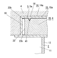
このコントローラ20は、図3に示すようにユニット化されたものであって、コントローラ収納部5aに収納される、つまり、コントローラ収納ボックス15a内部に収納されるものである。このコントローラ20は、難燃性のABS樹脂によって成形した略矩形函状体のハウジング23を有し、前面に明るさセンサ24を設けると共に裏面に電源線13の先端が連結する速結端子部25を設けているものである。なお、上記ハウジング23は、その前面以外の側面(両側面、裏面)においてその上下端部位置にそれぞれ外側方向に突出したつば片23bをフランジ状に形成させており、その上下面にコントローラ収納ボックス15aに設けた係止部16に係止される被係止部41を形成させており、また、前面の下部においては、カバー6の傾斜部7に合わせた傾斜23aが形成されているものである。また、コントローラ20の裏面からは照明部21への配電を行う配電線26が延出すると共に上記配電線26の先端にはコネクタ27が設けられている。
【0017】
一方、照明部21は、図5(b)に示すように、照明部収納部5bに装着される、つまり、照明部収納ボックス15b内部に装着される取付台座29と上記取付台座29に配置した照明光を発する複数の照明器具28から構成されるものである。取付台座29は凹溝状の被係止部41を有すると共に照明部21の長手方向に亘るように形成した台座であり、照明部収納ボックス15bの最奥部上部に設けた係合部16と上記被係止部41が係合して上がり框4の玄関幅方向である長手方向に亘って架設されるものである。上記照明器具28は、光源としてLED30を用い、上記LED30を基板31の前面に固定して形成したものである。この照明器具28を取付台座29に取り付けた際には基板31の前面が玄関土間1に向って面をなすものである。上記照明器具28は複数個用意されるものであって、上記取付台座29の長手方向に等間隔に配置されるものである。なお、上記照明部21にはコントローラ20を介して給電が行われるが、これは、照明器具28に連結した配電線32の先端に設けたコネクタ34と上記コントローラ20に連結した配電線26のコネクタ27とをコネクタ接続させて行われるものである。
【0018】
コントローラ20を収納するコントローラ収納ボックス15aは前面を開口した略矩形状のボックス体に形成されたものである。このコントローラ収納ボックス15aの背面部には玄関床面3の下方位置に配線した電源線13をコントローラ20の速結端子部25に連結させる挿通させるボックス貫通孔38aが形成されている。なお、玄関床面3の下方位置(電源線配線部42)に配線した電源線13は、上がり框4の下方に設けた貫通孔38を通ると共に上記ボックス貫通孔38aを通ってコントローラ20の速結端子部25に連結されるものである。また、コントローラ収納ボックス15aの照明部21に隣接する側面部には照明部21に向って配電線26,32を挿通させ得る挿通孔35が形成されている。ここで、このコントローラ収納ボックス15aにコントローラ20を装着した際には、図6及び図4に示すように、コントローラ20のハウジング23に形成したつば片23bがコントローラ20とコントローラ収納ボックス15aの内面との間に隙間空間10を形成するものである。この隙間空間10には、後述するが電源線13の照明装置8への連結施工作業の際に生じる電源線13の余長部分や配電線26,32やそのコネクタ27,34が収納されるものである。また、上記つば片23bにはコントローラ20をコントローラ収納ボックス15aの内部の所定位置に一意的に配置させる利点もあるものであり、これは後述するコントローラ収納ボックス15aに取り付けられるコントローラカバー6aに設けた採光窓39に対してコントローラ20の明るさセンサ24を合わせて配置する際に有用である。
【0019】
照明部21を装着する照明部収納ボックス15bは前面及び両側端を開口し、上がり框4の玄関幅方向に長手方向を有した柱状体に形成されたものである。したがって、コストを考慮して押出成形材で形成されることが好ましい。また、この照明部収納ボックス15bにはその長手方向に亘って配電線32を収納する凹溝片33を形成している。
【0020】
上述したように、本例では、照明装置8をコントローラ20と照明部21とで構成し、その収納部5もコントローラ収納部5aと照明部収納部5bとを有して構成しているものであるが、収納部5の前面に装着するカバー6もコントローラ20の前面を被覆するコントローラカバー6aと照明部21の前面を被覆する照明部カバー6bとで構成させている。コントローラカバー6aはその前面、つまり、カバー本体17に、採光窓39を設けてあり、コントローラ20に設けた明るさセンサ24への採光を行い得るようにしているものである。これにより、本例では、上記明るさセンサ24が前面に設けられているので、例えば、上がり框4の下面に明るさセンサ24を設けた場合の薄暗く検知されてしまうといった誤検知を避けることができるものであって、上記上がり框4の下面に明るさセンサ24を設けた場合と比較して玄関空間を正確に検知させることができるものである。そして、照明装置8の照明部21の制御を玄関空間の状態に合わせて行うことができるものである。また、照明部カバー6bはその傾斜部7を光が透過する光透過材、例えば、ポリカーボネードで形成させている。これにより、照明装置8の照明器具28が発する照明光を傾斜部7を通じて照明装置8及びカバー6の外方に照射することができ、ここで、傾斜部7は玄関土間1に向って面をなす部分であることから、玄関土間1のうちの立上り部2の近傍位置に上記照明光を集中的に照射させることができるものである。また、上述したように照明部21では照明装置28が玄関土間1に向って面をなすように取付台座29に取り付けられており、上記照明装置28と上記照明部カバー6bの傾斜部7は対向位置にあるものであって、上記傾斜部7には照明器具28から比較的強い照明光が照射されているものであり、上記傾斜部7を光透過材で形成することで上記照明器具28からの比較的強い照明光を玄関土間1に照射できるといった利点もあるものである。
【0021】
また、本例においては、図4(b)に示すように、照明装置8の外観を左右対称に見せることを期して、照明部21の長手方向の端部のうちのコントローラ20に隣接しない方の端部にはダミーとしてのコントローラカバー6cを装着している。これにより、玄関土間1から上記上がり框4を見た際に、上記上がり框4の下部に設けた玄関足元照明装置の正面外観を左右対称にするものであって外観の向上が図られているものである。
【0022】
また、本例においては、上がり框4の大切欠部14aの奥方(つまり、玄関床面3の下方位置)に電源線配線部42を設けてある。この電源線配線部42は、玄関床面3の下方位置に配線する電源線13の配線スペースである。
【0023】
以下、上述した玄関足元照明装置の施工作業を簡単に記す。玄関土間1に床面土台11を配置し、上記床面土台11の上面に上記上がり框4及び玄関床面3を配置し、上記床面土台11の前面にタイル12を接着剤等で貼着して立上り部2を形成させる。このとき、上記上がり框4は工場出荷段階で収納部5に照明装置8を装着すると共にカバー6を装着したものが用いられるものであるが、この施工段階で照明装置8のコントローラ20及びコントローラカバー6aを収納部5から取り外しておく。次に、玄関床面3の下方位置に電源線13を配線し、上記電源線13の先端を収納部5の貫通孔38に挿通させて収納部5に導入し、上記収納部5に導入した電源線13を掴んでその先端を玄関土間側前面に引張り出し、上記電源線13の先端を照明装置8のコントローラ20の速結端子部25に連結する。そして、上記電源線13と連結させて電気が供給されるようにした照明装置8を上がり框4の収納部5に再び挿入して装着し、カバー6を収納部5の前面に装着するものである。ここで、電源線13の照明装置8への連結施工作業においては、収納部5が前面に開口していることから収納部5に導入された電源線13を玄関土間1から目視確認できるものであり、施工作業者は容易に電源線13を掴んで前方に引張り出すことができるものである。
【0024】
【発明の効果】
上記のように本発明の請求項1記載の玄関足元照明装置にあっては、玄関土間から立設した立上り部の上部に玄関床面の玄関土間側前端部に水平配置した上がり框を位置させ、上がり框の下部に少なくとも玄関土間側である前面に開口した切欠部を形成し、上記切欠部に少なくとも前面に開口した収納ボックスを固着させて収納部を形成し、上記収納部にコントローラと照明部とで構成した照明装置を配置し、下方にいく程奥方に位置するような傾斜部が形成されたカバーを上記収納部の開口を閉塞するように装着したので、上記玄関土間に立つ人から上記カバーを見えにくいものとすることができ、更に、玄関土間に立つ人の見下ろし角度(玄関土間に対する視線の角度)よりも傾斜部の傾斜角度(玄関土間に対する傾斜の角度)を浅い角度にさせると、上記玄関土間に立つ人の視界から上記カバーを見えなくさせることができるものであって、玄関土間に立つ人には上記玄関において玄関足元照明装置の存在を感じさせにくくすることができ、玄関の外観及びその意匠性を向上させることができるのであり、また、切欠部の上端部分における前端部分に収納ボックスの上部における前端部分を臨ませ、カバーの上端部に上方に突出すると共にカバーの水平方向に亘る被覆突起片を設け、上記切欠部の上端部における前端部分と収納ボックスの上部における前端部分とに上記被覆突起片の裏面を当接したので、切欠部の上端部における前端部分と収納ボックスの上部における前端部分は、カバーの上端に亘って設けられる被覆突起片の裏面に当接して位置するものであって、ここで、切欠部の上端部における前端部分とは上がり框の前面の一部分であることから、カバーはその被覆突起片が上がり框の前面に隙間無く沿うものであり、玄関土間に立つ人から収納ボックス15や上がり框の切断面である切欠部を完全に見えなくさせることができて玄関の外観及びその意匠性を向上させることができると共に、施工的にも収納ボックスの切欠部への納まりを良くできるものであり、また、上記カバーを、コントローラを覆うコントローラカバーと、照明部を覆う照明カバーと、照明部の長手方向の端部のうちのコントローラに隣接しない方の端部に設けるダミーとしてのコントロールカバーとで構成したので、玄関土間から上記上がり框を見た際に、上記上がり框の下部に設けた玄関足元照明装置の正面外観を左右対称にするものであって外観の向上を図ることができるのである。
【0025】
また、本発明の請求項2記載の玄関足元照明装置にあっては、請求項1の効果に加えて、照明カバーの傾斜部を光が透過する透光材で形成させたので、照明装置の照明部での照明光を照明カバーの傾斜部を通じて外方に照射することができ、ここで、傾斜部は玄関土間に向って面をなす部分であることから、玄関土間のうちの立上り部の近傍位置に上記照明光を集中的に照射させることができるものである。
【0026】
また、本発明の請求項3記載の玄関足元照明装置にあっては、請求項1の効果に加えて、上記収納ボックスにカバーを係脱自在に装着したので、収納部に装着する照明装置は、実質的には、収納ボックスの内部に装着されるものであるが、上記収納ボックスの前面の開口を閉塞するカバーを収納ボックスに対して係脱自在にしたことで、上記カバーを収納ボックスに対して容易に着脱自在にするものであって、例えば、照明装置の上がり框への配置施工や照明装置のメンテナンスや照明装置の交換等を容易に行わせることができるものである。
【図面の簡単な説明】
【図1】本発明の実施の形態の例を示す側面断面図である。
【図2】同上の斜視図である。
【図3】同上の照明装置の収納部への収納施工作業を示す概略斜視図である。
【図4】同上の玄関足元照明装置を示すものであり、(a)は上面図であり、(b)は正面図である。
【図5】(a)は図4のA−A線断面図であり、(b)は図4のB−B線断面図である。
【図6】図1のC部分の拡大図である。
【図7】従来技術の例を示す斜視図である。
【符号の説明】
1 玄関土間
2 立上り部
3 玄関床面
4 上がり框
5 収納部
6 カバー
7 傾斜部
8 照明装置
9 被覆突起片
14 切欠部
14a 大切欠部
15 収納ボックス
15a コントローラ収納ボックス
18 係合片
19 係合凹部
20 コントローラ[0001]
BACKGROUND OF THE INVENTION
The present invention relates to an entrance foot illuminating device in which an illuminating device is arranged on a rising ridge of the entrance.
[0002]
[Prior art]
Conventionally, in the footstep lighting device that illuminates the front door 1FIG.As shown in FIG. 4, there is a device that irradiates the entrance soil 1 with the lighting device 8 ′ disposed on the entrance wall surface 40. In such an entrance foot illuminating device, the illuminating device 8 'disposed on the entrance wall surface 40 is reminiscent of the design that the entrance foot illuminating device is retrofitted after the entrance construction, It does not give consumers the appeal of attaching the front foot lighting device to the front door, and the lighting device 8 ′ disposed on the front wall surface 40 cannot irradiate only the foot portion between the front doors 1. there were.
[0003]
[Problems to be solved by the invention]
Thus, a front foot illuminating device has been proposed in which an illuminating device is arranged at the lower part of the raised ridge 4 provided at the front end portion of the front entrance floor 3 between the front and front soils. In this entrance foot illuminator, the illuminator provided at the lower part of the eaves ridge 4 is effective as being able to illuminate the foot portion of the entrance soil 1 at the lower position of the eaves 4. Since the device was visible, the problem of improving the appearance design of the entrance was still unsolved, and improvement in the appearance design of the entrance foot lighting device was desired.
[0004]
The present invention has been made in view of the above points, and it is an object of the present invention to provide an entrance foot illuminating device having improved appearance design in an entrance foot illuminating device composed of an illuminating device disposed on an uphill of an entrance. To do.
[0005]
[Means for Solving the Problems]
In order to solve the above problems, in the entrance foot lighting device according to claim 1 of the present invention, the entrance floor 2 is horizontally disposed at the front end portion of the entrance floor surface 3 at the upper portion of the rising portion 2 erected from the entrance soil 1. Position the raised ridge 4A cut at the bottom of the riser 4 with an opening at least in front of the front door The notch part 14 is formed, and a storage box 15 opened at least on the front surface is fixed to the notch part 14 to form the storage part 5.In the storage part 5Consists of a controller 20 and an illumination unit 21Arrange lighting device 8Then, the cover 6 having the inclined portion 7 formed so as to be located in the back is attached so as to close the opening of the storage portion 5, and the storage box 15 is attached to the front end portion of the upper end portion of the notch portion 14. The upper end of the cover 6 faces upward, the cover 6 protrudes upward, and the cover projection 9 is provided in the horizontal direction. The front end of the upper end of the notch 14 and the upper portion of the storage box 15 are provided. The back surface of the covering projection piece 9 is brought into contact with the front end portion of the cover 6, the cover 6 is covered with a controller cover 6 a that covers the controller 20, a lighting cover 6 b that covers the lighting unit 21, and a longitudinal end of the lighting unit 21. It was comprised with the control cover 6c as a dummy provided in the edge part which is not adjacent to our controller 20It is characterized byThe
[0006]
ThisAs a result,A rising ridge 4 placed horizontally at the front end of the entrance floor side of the entrance floor 3 is positioned above the rising portion 2 erected from the entrance soil 1, and at least a notch opening at the front of the front side of the entrance soil at the bottom of the rising ridge 4 14 is formed, and a storage box 15 having at least a front opening is fixed to the cutout portion 14 to form the storage portion 5, and the lighting device 8 including the controller 20 and the lighting portion 21 is disposed in the storage portion 5. Since the cover 6 in which the inclined portion 7 is formed so as to be located in the back as it goes downward is mounted so as to close the opening of the storage portion 5,It is possible to make the cover 6 difficult to see from a person standing between the entrance soils 1, and further, the inclination angle of the inclined portion 7 than the looking down angle of the person standing between the entrance soils 1 (the angle β of the line of sight with respect to the entrance soil 1). When the angle of inclination α with respect to the entrance soil 1 is set to a shallow angle, the inclined portion 7 of the cover 6 can be made invisible from the view of a person standing in the entrance soil 1. It is possible to make it difficult for a standing person to feel the presence of the lighting device 8 at the entrance, and to improve the appearance and design of the entrance.Further, the front end portion of the upper portion of the storage box 15 faces the front end portion of the upper end portion of the cutout portion 14, and the cover 6 protrudes upward at the upper end portion of the cover 6 and is provided with a covering projection piece 9 extending in the horizontal direction of the cover 6, Since the back surface of the covering projection piece 9 is brought into contact with the front end portion at the upper end portion of the cutout portion 14 and the front end portion at the upper portion of the storage box 15, the front end portion at the upper end portion of the cutout portion 14 and the front end portion at the upper portion of the storage box 15 The portion is located in contact with the back surface of the covering projection piece 9 provided over the upper end of the cover 6. Here, the front end portion at the upper end portion of the notch portion 14 is a part of the front surface of the raised ridge 4. Therefore, the cover 6 has the covering projection piece 9 that rises and follows the front surface of the ridge 4 without a gap, and the person who stands between the front doors 1 cuts the storage box 15 and the ridge 4. The cutout portion 14 can be completely invisible, the appearance and design of the entrance can be improved, and the storage of the storage box 15 in the cutout portion 14 can be improved in terms of construction. . In addition, the cover 6 is provided on a controller cover 6 a that covers the controller 20, a lighting cover 6 b that covers the lighting unit 21, and a dummy that is provided on the end of the lighting unit 21 in the longitudinal direction that is not adjacent to the controller 20. The front cover of the front foot illuminating device provided at the lower part of the raised ridge 4 is made symmetrical when the raised ridge 4 is viewed from the entrance soil 1. Improvements are being made.
[0007]
MaOf the present inventionClaim 2In the entrance foot lighting device according to claim 1,The inclined portion 7 of the illumination cover 6b is formed of a translucent material that transmits light.It is characterized by that. As a result, the lighting device 8In the lighting unit 21Lighting lightLighting cover 6bThrough the ramp 7OutsideHere, since the inclined portion 7 is a portion that forms a surface toward the entrance soil 1, the illumination light is concentrated at a position near the rising portion 2 in the entrance soil 1. It can be irradiated.
[0008]
In addition, the present inventionClaim 3In the front foot lighting device according to claim 1,,the aboveThe cover 6 is detachably attached to the storage box 15. Thereby, the lighting device 8 to be mounted on the storage unit 5 is substantially mounted inside the storage box 15, but the cover 6 that closes the opening on the front surface of the storage box 15 is attached to the storage box 15. The cover 6 can be easily attached to and detached from the storage box 15 by being freely detachable from the storage box 15. For example, the construction of the lighting device 8 on the rising wall 4 and the maintenance of the lighting device 8 can be performed. And replacement of the lighting device 8 can be performed easily.is there.
[0009]
DETAILED DESCRIPTION OF THE INVENTION
Hereinafter, the present invention will be described based on embodiments shown in the accompanying drawings.
[0010]
1 to 6 show an example of an embodiment of the present invention. As shown in FIG. 1, this entrance structure has a floor base 11 disposed between entrance soils 1 laid at the entrance, and a tile 12 is attached to the front surface of the floor base 11 that is between the entrance soils. 2 is set up, and a raised ridge 4 is provided at the front end of the entrance floor surface 3 between the entrance soils, and the upward ridge 4 is positioned so as to protrude to the entrance soil side at the upper part of the uplift portion 2. A storage unit 5 that opens to the front is provided at the lower part, and a lighting device 8 that irradiates the entrance soil 1 near the rising portion is mounted on the storage unit 5, and the opening of the storage unit 5 is closed on the front of the storage unit 5. The cover 6 to be attached is detachably mounted. A power line 13 made of a VFF cable or the like is wired below the entrance floor 3 and the tip of the power line 13 is connected to the lighting device 8.
[0011]
Here, the storage portion 5 is formed by forming a notch portion 14 opened to the lower surface and the front surface in the lower portion of the raised ridge 4 and arranging a storage box 15 opening to the front surface to the notch portion 14. . The storage box 15 is formed of ABS (acrylonitrile, butadiene, styrene) resin, and is fixed to the upper surface and the back surface of the notch 14 with an adhesive interposed therebetween. That is, the lighting device 8 is mounted inside the storage box 15. A locking portion 16 is provided on the inner wall surface of the storage box 15, and the lighting device 8 inserted from the front surface is engaged with the storage box 15 to be detachably mounted. In addition, the storage box 15 is formed such that the upper and lower protrusion lengths differ, that is, the upper portion of the storage box 15 protrudes forward compared to the lower part. The front end portion of the upper portion of the storage box 15 faces the front end portion of the upper end portion of the cutout portion 14. In this way, the storage portion 5 of the raised basket 4 to which the lighting device 8 is mounted is formed by the storage box 15, and the lighting device 8 is detachably mounted inside the storage box 15, so that the lighting device 8 is removed from the storage portion 5. It is ensured that it can be easily removed for maintenance and replacement. That is, when the lighting device 8 is mounted directly on the notch portion 14 positioned at the upper end of the rising portion 2, the tile 12 through the adhesive to the floor base 11 performed in the construction of the rising portion 2 described later. The adhesive may accidentally adhere the tile 12 and the lighting device 8 at the time of sticking, and the lighting device 8 may rise almost permanently and not come off the ridge 4 in some cases. In this example, such a situation can be avoided. Also, from an electrical point of view, the lighting device 8 is mounted inside the storage box 15 as described above, so that it is possible to avoid the lighting device 8 through which electricity passes directly from being brought into contact with the wood part such as the firewood 4. Safety can be improved.
[0012]
In addition, a cover 6 that closes the opening is detachably attached to the opening on the front surface side of the storage unit 5 between the front doors, but is substantially attached to the front of the storage box 15 that forms the storage unit 5. It is detachably mounted. The cover 6 includes a cover main body 17 that closes the opening on the front surface of the storage box 15 and a rear side of the cover main body 17 that engages with a locking recess 19 provided on the upper wall surface and the lower wall surface of the inner wall surface of the storage box 15. And a pair of engaging pieces 18 projecting from each other. As described above, the cover 6 that closes the opening on the front surface of the storage box 15 is detachable from the storage box 15, so that the cover 6 can be easily attached to and detached from the storage box 15. Thus, for example, the arrangement and construction of the lighting device 8 on the lifting rod 4, the maintenance of the lighting device 8, the replacement of the lighting device 8, and the like can be easily performed.
[0013]
The cover main body 17 is provided with a covering projection piece 9 extending in the horizontal direction of the cover 6 and protruding upward. The cover 6 is attached to the front surface of the storage box 15 by engagement of the engagement piece 18 and the locking recess 19 of the storage box 15. At this time, the covering projection piece 9 14 is in contact with the front end portion at the upper end portion of 14 and the front end portion at the upper portion of the storage box 15. Here, since the front end portion at the upper end portion of the notch portion 14 is a part of the front surface of the raised ridge 4, the covering projection piece 9 of the cover 6 is raised and extends along the front surface of the ridge 4 without any gaps. It is possible to make the storage box 15 and the cut surface 14 which is the cut surface of the raised ridge 4 completely invisible from a standing person, improve the appearance of the entrance and its design, and also in terms of construction In this way, the storage box 15 is better fitted into the cutout portion 14.
[0014]
In addition, an inclined portion 7 is formed in the lower portion of the cover 6, that is, in the lower portion of the cover main body 17, so as to be located in the back, which is in the opposite direction to the front side of the front door. The inclined portion 7 is provided so as to make the cover 6 invisible from the field of view of a person standing between the front doors 1, and the upper end position of the inclined portion 7 is positioned as high as possible above the cover 6. It is preferable to set the inclination angle (angle α with respect to the entrance soil 1) to a shallow angle. That is, when the inclination angle of the inclined portion 7 (the inclination angle α with respect to the entrance soil 1) is made shallower than the look-down angle of the person standing in the entrance soil 1 (the angle β of the line of sight with respect to the entrance soil 1), the above-mentioned entrance soil 1 It is possible to make the inclined portion 7 of the cover 6 invisible from the field of view of a person standing on the floor, and it is possible to make it difficult for a person standing between the front doors 1 to feel the presence of the lighting device 8 at the front door. The appearance of the entrance and its design are improved. The inclined portion 7 of the cover 6 is formed of a light transmitting material through which light passes, for example, polycarbonate, etc., and this will be described later.
[0015]
Moreover, the illuminating device 8 is provided along the longitudinal direction which is the entrance width direction of the rising ridge 4, and in this example, as shown in FIG.4 and FIG.5, the illumination part 21 and the controller 20 are arrange | positioned adjacently. Is used. This is intended to allow the lighting unit 21 and the controller 20 to be replaced separately when the lighting device 8 fails. Here, the illuminating part 21 constitutes a large part of the illuminating device 8 and is an illuminating part that illuminates the entrance soil 1.TheThe controller 20 constitutes a part of the lighting device 8 and controls the lighting unit 21. The controller 20 requires an installation portion having a depth dimension larger than that of the illumination unit 21 as a result of the large number of components and the arrangement area thereof as compared with the illumination unit 21. Thus, the storage section 5 for storing the lighting device 8 has a controller storage section 5a for storing the controller 20 and an illumination section storage section 5b for storing the illumination section 21, and the cutout portion 14 of the raised basket 4 is also stored in the storage box. 15 also includes an important notch portion 14a in which the controller 20 is disposed and a small notch portion 14b in which the illumination portion 21 is disposed, and a controller storage box 15a that forms the controller storage portion 5a and an illumination portion storage that forms the illumination portion storage portion 5b. A box 15b is provided. In addition, since the illumination part 21 and the controller 20 are arrange | positioned adjacently, the important notch part 14a and the small notch part 14b are formed continuously.
[0016]
The controller 20 is unitized as shown in FIG. 3, and is housed in the controller housing 5a, that is, housed in the controller housing box 15a. This controller 20 has a housing 23 having a substantially rectangular box-shaped body formed of flame-retardant ABS resin, provided with a brightness sensor 24 on the front surface, and a quick connection terminal portion 25 to which the tip of the power line 13 is connected on the rear surface. Is provided. The housing 23 is formed with flanges 23b projecting outward at the upper and lower end positions on the side surfaces (both side surfaces and back surface) other than the front surface, and the controller storage box on the upper and lower surfaces. A locked portion 41 that is locked to the locking portion 16 provided in 15a is formed, and an inclined portion 23a that matches the inclined portion 7 of the cover 6 is formed in the lower portion of the front surface. is there. A distribution line 26 that distributes power to the illumination unit 21 extends from the back surface of the controller 20, and a connector 27 is provided at the tip of the distribution line 26.
[0017]
On the other hand, as shown in FIG. 5B, the illumination unit 21 is mounted on the illumination unit storage unit 5 b, that is, disposed on the mounting base 29 and the mounting base 29 mounted in the illumination unit storage box 15 b. It comprises a plurality of lighting fixtures 28 that emit illumination light. The mounting pedestal 29 is a pedestal formed with a recessed groove-like locked portion 41 and extending in the longitudinal direction of the illuminating unit 21, and the engaging portion 16 provided at the uppermost uppermost part of the illuminating unit storage box 15 b. The to-be-latched portion 41 engages and rises and extends over the longitudinal direction, which is the entrance width direction of the eaves 4. The lighting fixture 28 is formed by using the LED 30 as a light source and fixing the LED 30 to the front surface of the substrate 31. When the lighting fixture 28 is attached to the mounting base 29, the front surface of the substrate 31 faces the entrance soil 1. A plurality of the lighting fixtures 28 are prepared, and are arranged at equal intervals in the longitudinal direction of the mounting base 29. The lighting unit 21 is supplied with power via the controller 20, which is a connector 34 provided at the tip of the distribution line 32 connected to the lighting fixture 28 and a connector of the distribution line 26 connected to the controller 20. 27 is connected to a connector.
[0018]
The controller storage box 15a for storing the controller 20 is formed in a substantially rectangular box with an open front. A box through-hole 38 a is formed in the back surface of the controller storage box 15 a so that the power line 13 wired below the entrance floor 3 is connected to the quick connection terminal 25 of the controller 20. The power line 13 wired below the entrance floor 3 (the power line wiring portion 42) passes through the through hole 38 provided below the rising wall 4 and passes through the box through hole 38a to quickly connect the controller 20. It is connected to the terminal portion 25. Further, an insertion hole 35 through which the distribution lines 26 and 32 can be inserted toward the illumination unit 21 is formed in a side surface portion adjacent to the illumination unit 21 of the controller storage box 15a. Here, when the controller 20 is mounted on the controller storage box 15a, as shown in FIGS. 6 and 4, the collar piece 23b formed on the housing 23 of the controller 20 is connected to the inner surface of the controller 20 and the controller storage box 15a. A gap space 10 is formed between the two. As will be described later, this gap space 10 accommodates an extra length portion of the power supply line 13 generated when the power supply line 13 is connected to the lighting device 8, distribution lines 26 and 32, and connectors 27 and 34 thereof. It is. Further, the collar piece 23b has an advantage that the controller 20 is uniquely arranged at a predetermined position inside the controller storage box 15a. This is provided on a controller cover 6a attached to the controller storage box 15a described later. This is useful when the brightness sensor 24 of the controller 20 is arranged with respect to the daylighting window 39.
[0019]
The lighting unit storage box 15b to which the lighting unit 21 is mounted is formed in a columnar body having a front side and both side ends opened and having a longitudinal direction in the entrance width direction of the raised bowl 4. Therefore, it is preferable to form with an extrusion molding material in consideration of cost. Moreover, the groove part 33 which accommodates the distribution line 32 over the longitudinal direction is formed in this illumination part storage box 15b.
[0020]
As described above, in this example, the lighting device 8 includes the controller 20 and the lighting unit 21, and the storage unit 5 includes the controller storage unit 5a and the lighting unit storage unit 5b. However, the cover 6 attached to the front surface of the storage unit 5 is also composed of a controller cover 6 a that covers the front surface of the controller 20 and an illumination unit cover 6 b that covers the front surface of the illumination unit 21. The controller cover 6a is provided with a daylighting window 39 on the front surface thereof, that is, the cover main body 17, so that the brightness sensor 24 provided in the controller 20 can be daylighted. Thereby, in this example, since the brightness sensor 24 is provided on the front surface, for example, it is possible to avoid an erroneous detection such that the brightness sensor 24 is detected as being dim when the brightness sensor 24 is provided on the lower surface of the raised ridge 4. Thus, the entrance space can be accurately detected as compared with the case where the brightness sensor 24 is provided on the lower surface of the rising ridge 4. And control of the illumination part 21 of the illuminating device 8 can be performed according to the state of an entrance space. In addition, the illumination unit cover 6b is formed by forming a light transmitting material, such as polycarbonate, through which the inclined portion 7 transmits light.The ThisThereby, the illumination light emitted from the luminaire 28 of the illuminating device 8 can be irradiated to the outside of the illuminating device 8 and the cover 6 through the inclined portion 7, where the inclined portion 7 has a surface facing toward the entrance soil 1. Since it is a part to be formed, the illumination light can be intensively applied to a position in the vicinity of the rising portion 2 in the entrance soil 1. Further, as described above, in the illuminating unit 21, the illuminating device 28 is attached to the mounting base 29 so as to form a surface toward the entrance soil 1, and the illuminating device 28 and the inclined portion 7 of the illuminating unit cover 6b face each other. The inclined portion 7 is irradiated with relatively strong illumination light from the luminaire 28. By forming the inclined portion 7 with a light transmitting material, the luminaire 28 There is also an advantage that the relatively strong illumination light can be irradiated to the entrance soil 1.
[0021]
Further, in this example, as shown in FIG. 4B, one of the end portions in the longitudinal direction of the illumination unit 21 that is not adjacent to the controller 20 in order to make the appearance of the illumination device 8 appear symmetrical. At the end of the controller cover as a dummy6cWearing. As a result, when the rising ridge 4 is viewed from the entrance soil 1, the front appearance of the entrance foot illuminating device provided at the lower part of the rising ridge 4 is made symmetrical, and the appearance is improved. is there.
[0022]
Further, in this example, the power line wiring portion 42 is provided behind the important notch portion 14a of the rising ridge 4 (that is, a position below the entrance floor 3). The power line wiring portion 42 is a wiring space for the power line 13 that is wired below the entrance floor 3.
[0023]
Hereinafter, the construction work of the above-mentioned entrance foot lighting device will be briefly described. A floor base 11 is disposed between the front doors 1, the raised ridge 4 and the front floor 3 are disposed on the upper surface of the floor base 11, and tiles 12 are adhered to the front surface of the floor base 11 with an adhesive or the like. The rising portion 2 is formed. At this time, the rising rod 4 is the one in which the lighting device 8 is mounted on the storage unit 5 and the cover 6 is mounted at the factory shipment stage. At this construction stage, the controller 20 and the controller cover 6a of the lighting device 8 are used. Is removed from the storage unit 5. Next, the power supply line 13 is wired below the entrance floor 3, the tip of the power supply line 13 is inserted into the storage part 5 through the through hole 38 of the storage part 5, and is introduced into the storage part 5. The power supply line 13 is gripped and the tip is pulled out to the front surface between the front door and the front end of the power supply line 13 is connected to the quick connection terminal portion 25 of the controller 20 of the lighting device 8. Then, the lighting device 8 connected to the power supply line 13 and supplied with electricity is inserted again into the storage unit 5 of the basket 4 and mounted, and the cover 6 is mounted on the front surface of the storage unit 5. . Here, in the connection construction work of the power line 13 to the lighting device 8, since the storage part 5 is open on the front surface, the power line 13 introduced into the storage part 5 can be visually confirmed from the entrance soil 1. Yes, the construction worker can easily grasp the power line 13 and pull it forward.is there.
[0024]
【The invention's effect】
As described above, in the entrance foot illuminating device according to claim 1 of the present invention, the rising hook horizontally disposed at the front end portion between the entrance soil of the entrance floor surface is positioned at the upper portion of the rising portion standing from the entrance soil,Form a notch that opens at the front side that is at least the side of the front soil at the lower part of the rising ridge, and fix a storage box that opens at least to the front to the notch to form a storage part,In the storage sectionConsists of controller and lighting unitPlace lighting equipmentThen, a cover having an inclined portion formed so as to be located in the back as it goes downward is mounted so as to close the opening of the storage portion.Because,UpIt is possible to make it difficult for the person standing between the entrance soils to see the cover, and the inclination angle of the inclined part (the inclination of the slope between the entrance soils) is smaller than the look down angle of the person standing between the entrance soils (the angle of the line of sight relative to the entrance soil). If the angle is set to a shallow angle, the cover can be made invisible from the view of the person standing between the entrance soils, and the person standing between the entrance soils feels the presence of the entrance foot lighting device at the entrance. Can improve the appearance and design of the entrance.In addition, the front end portion of the upper portion of the storage box faces the front end portion of the upper end portion of the notch, and the cover protruding piece extending in the horizontal direction of the cover is provided at the upper end portion of the cover. Since the back surface of the covering projection piece is in contact with the front end portion at the upper end portion of the cutout portion and the front end portion at the upper portion of the storage box, the front end portion at the upper end portion of the cutout portion and the front end portion at the upper portion of the storage box are It is located in contact with the back surface of the covering projection piece provided over the upper end of the cover, and the front end portion at the upper end portion of the notch portion is a part of the front surface of the raised ridge, so that the cover is The covering protrusions are raised and follow the front surface of the ridge without any gaps, and the person standing between the front doors cannot completely see the storage box 15 or the cut portion of the rising ridge cut surface. It is possible to improve the appearance and design of the entrance, and to improve the fit in the cutout portion of the storage box in terms of construction, and the controller cover that covers the controller. And a lighting cover that covers the lighting part, and a control cover as a dummy provided at the end of the lighting part in the longitudinal direction that is not adjacent to the controller. In this case, the front appearance of the front foot illuminating device provided in the lower part of the raised heel is made symmetrical, and the appearance can be improved.
[0025]
MaOf the present inventionClaim 2In the entrance foot illuminating device described above, in addition to the effect of claim 1,The inclined part of the lighting cover is made of a translucent material that transmits lightSo the lighting equipmentIn the lighting sectionLighting lightLighting coverThrough the rampOutsideHere, since the inclined portion is a portion that forms a surface between the entrance soils, the illumination light can be intensively applied to a position near the rising portion between the entrance soils. It can be done.
[0026]
In addition, the present inventionClaim 3In the entrance foot lighting device described above, in addition to the effect of claim 1, since the cover is detachably mounted on the storage box, the lighting device mounted on the storage portion is substantially a storage box. The cover that closes the front opening of the storage box is made detachable from the storage box, so that the cover can be easily attached to and detached from the storage box. For example, it is possible to easily perform the installation and construction of the lighting device on the rising pole, the maintenance of the lighting device, the replacement of the lighting device, and the like.
[Brief description of the drawings]
FIG. 1 is a side sectional view showing an example of an embodiment of the present invention.
FIG. 2 is a perspective view of the same.
FIG. 3 is a schematic perspective view showing a storage work operation in a storage unit of the lighting device same as above.
FIGS. 4A and 4B show the entrance foot illumination device of the above, wherein FIG. 4A is a top view and FIG. 4B is a front view.
5A is a cross-sectional view taken along line AA in FIG. 4, and FIG. 5B is a cross-sectional view taken along line BB in FIG.
6 is an enlarged view of a portion C in FIG.
[Fig. 7]It is a perspective view which shows the example of a prior art.
[Explanation of symbols]
1 Entrance soil
2 Rising part
3 entrance floor
4 Going up
5 storing section
6 Cover
7 Inclined part
8 Lighting equipment
9 Coated protrusion
14 Notch
14a Important missing part
15 Storage box
15a Controller storage box
18 engagement piece
19 Engaging recess
20 controller