JP3689623B2 - X-ray imaging device - Google Patents
X-ray imaging device Download PDFInfo
- Publication number
- JP3689623B2 JP3689623B2 JP2000269214A JP2000269214A JP3689623B2 JP 3689623 B2 JP3689623 B2 JP 3689623B2 JP 2000269214 A JP2000269214 A JP 2000269214A JP 2000269214 A JP2000269214 A JP 2000269214A JP 3689623 B2 JP3689623 B2 JP 3689623B2
- Authority
- JP
- Japan
- Prior art keywords
- ray
- incident
- crystal
- plate
- beams
- Prior art date
- Legal status (The legal status is an assumption and is not a legal conclusion. Google has not performed a legal analysis and makes no representation as to the accuracy of the status listed.)
- Expired - Fee Related
Links
Images


Classifications
-
- G—PHYSICS
- G21—NUCLEAR PHYSICS; NUCLEAR ENGINEERING
- G21K—HANDLING OF PARTICLES OR IONISING RADIATION NOT OTHERWISE PROVIDED FOR; IRRADIATION DEVICES; GAMMA RAY OR X-RAY MICROSCOPES
- G21K2207/00—Particular details of imaging devices or methods using ionizing electromagnetic radiation such as X-rays or gamma rays
- G21K2207/005—Methods and devices obtaining contrast from non-absorbing interaction of the radiation with matter, e.g. phase contrast
Landscapes
- Analysing Materials By The Use Of Radiation (AREA)
Description
【0001】
【発明の属する技術分野】
本発明はX線撮像装置に係わり、特に物体の内部を非破壊的に検査するX線撮像装置に関する。
【0002】
【従来の技術】
物体内部を非破壊で検査する方法として、X線が試料を透過する際に生じるX線の振幅の変化を利用するX線撮像装置が広く普及している。この装置で取得される像は、試料のX線吸収分布を示すものである。ところで、X線が試料を透過する際、X線の振幅の他に位相も変化する。一般的に位相の変化は吸収の変化に比べて顕著であるため、この変化を捉えることにより、高感度に物体内部を観測することができる。この位相変化を利用したものとしては、特開平4−348262号公報に記載されたものや、特開平10−248833号公報に記載されたものなどがある。これら位相コントラスト型X線撮像装置では、従来の振幅の変化を検出する撮像装置では観察することができなかった生体軟部組織を無造影で観察することができる。
【0003】
上記公報に記載された装置は、いずれもX線用の干渉計を用いて位相の変化を検出している。X線干渉計には、ボンゼ・ハート型干渉計(Appl. Phys. Lett. 6,155(1965)に記載されたようなもの)や、この型の干渉計を複数の結晶ブロックに分割したものなどを用いている。ボンゼ・ハート型干渉計は、等間隔で平行に配置された3枚の歯(ビームスプリッタ、ミラー、アナライザー)を持った結晶ブロックで構成される。それぞれの歯でラウエケースの回折を利用して、ビームの分割、反射、結合を行っている。1枚目の歯(スプリッタ)で入射X線を2つのビームに分割し、2枚目の歯(ミラー)で分割されたビームをそれぞれ回折し、3枚目の歯(アナライザー)で分割されたビームを再び結合し、干渉ビームを形成している。
【0004】
この干渉計の一方の光路内に試料を設置すると、試料を透過したビームの位相が試料の位相分布に応じて変化する。このため、アナライザーで他方のビーム(参照波)と結合させると、干渉により位相の変化が干渉ビームの強度変化となって現れる。しかし、この強度変化からだけでは試料による位相変化量を精度良く求めることはできない。そこで、分割されたビームのいずれかの光路内に位相シフタを設置し、バックグランドの位相をずらして複数の干渉ビーム像を測定する。そして、測定後にこれら干渉ビーム像から計算で試料の位相像を求めている。
【0005】
【発明が解決しようとする課題】
上記干渉計でビームの分割や結合に使用されているラウエケースの回折では、入射X線が角度発散を持つとき、X線は結晶内で大きく広がって進むことになる(ボルマン・ファン効果)。この広がりは入射ビームの発散角の100000倍程度になる。このため、入射角がわずかにずれているだけでも、結晶内でのX線の光路は大きく変わってしまうので、信号波と参照波が同じ場所で結合されなくなる。この結果、コヒーレント長の短いX線ではビジビリティー(Visibility)が低下したり、ビームが干渉しなくなったりする場合があった。また、試料に入射したX線は試料と周囲との屈折率の違いにより、ごく僅かであるが屈折される。この屈折は空間的に一様ではないために、結晶内での光路が場所によって様々に変化し、その結果、アナライザーから出射される試料像がぼけて空間分解能が低下してしまうという欠点があった。このため、これまでの研究でよく利用されている測定条件(入射X線の波長0.07nm、アナライザーの歯の厚さ1mm)における空間分解能は30μm程度であり、生体軟部組織を構成する個々の細胞の状態や細胞内の器官や構造の観察等といった微視的な観察はできなかった。
【0006】
本発明の目的は、ラウエケースの回折によるビームの結合とは別の方法でビームを結合するX線干渉計を用いることにより、ビジビリティーが高くかつ高空間分解能なX線位相像の取得が可能な位相コントラスト型X線撮像装置を提供することにある。
【0007】
【課題を解決するための手段】
上記で説明したように、従来の位相コントラスト型X線撮像装置のビジビリティーや空間分解能の低下は、X線干渉計内で信号波と参照波の結合にラウエケースの回折を用いたことに起因する。したがって、ラウエケースの回折によるビームの結合の代わりに、ブラッグケースの回折によるビームの結合を用いることにより上記課題を解決することができる。しかし、通常のブラッグケースの回折では、1本の入射ビームに対して、回折ビームも1本であり、ビームを結合することはできない。そこで、本発明ではブラッグケースの同時反射を利用してビームを結合する。同時反射とは、入射X線が複数の格子面に対して、ブラッグの回折条件を同時に満たしたときに生じる回折現象のことをいい、入射X線は各回折格子面で回折され、複数のビームに分割されたり、あるいは逆に複数の入射X線が1本のビームに結合されたりする。通常のX線回折と同様に、ブラッグケースとラウエケースが存在し、さらに入射X線と回折されたX線のなす面がすべて平行な場合(coplanar)と、非平行な場合(nonplanar)とに区別される。以下本発明で使用するブラッグケースの同時反射について、coplanarとnonplanarに区別して説明する。
【0008】
coplanarの同時反射の例として、(n11)面と(n−1−1)面の同時反射について説明する。図1(a)に結晶表面に平行な格子面を(m00)とした場合の各格子面の関係を示す。(m00)面と(n11)面のなす角θaは、次の〔数1〕で与えられる。また、(m00)面と(n−1−1)面のなす角θa′も同様に〔数1〕で与えられる。
【0009】
【数1】

結晶を図1に示すようにθ回転させたとき、(n11)面及び(n−1−1)面に対する入射X線1の入射角が等しくなるのは、入射X線1が結晶表面に垂直に入射する場合だけである。このとき、(n11)面に対する入射角をθB、(n−1−1)面に対する入射角をθB′としたとき、θa=θa′=θB=θB′となる。入射X線1の波長λが下記の〔数2〕を満たすとき、入射X線1は(n11)面及び(n−1−1)面の回折条件を同時に満足するので、入射X線は2方向に回折され、回折光2及び回折光3に分割される。但し、dは(n11)面の格子間隔である。また、逆に回折光2及び回折光3の方向から〔数2〕で与えられた波長のX線が入射した場合は図1(b)に示すように、それぞれ(n11)面及び(n−1−1)面により回折され、1本のビームに結合され入射X線1の逆方向に出射される。
【0011】
【数2】
次に、(n11)面と(n−1−1)面を例として、nonplanarの同時反射について説明する。ここで、結晶表面に平行な格子面を(m00)面とし、[011]面はx−y面に平行であるとする。(m00)面と(n11)面のなす角をθa、(m00)面とx−y面のなす角をθbとしたとき、(n11)面の回折格子ベクトルgの単位ベクトルnは〔数3〕となる。
【0013】
【数3】
【0014】
【数4】
【0015】
【数5】
【0016】
【数6】
以上から、dρ=0のときθi=θi′となり、入射X線の波長λが下記〔数7〕を満たしていれば、入射X線は(n11)及び(n−1−1)面の同時反射により、波数ベクトルkhのX線とkh′のX線に分割されることが分かる。ただし、dは(n11)面の格子面間隔である。
【0018】
【数7】
【0019】
【数8】
【0020】
【数9】
【0021】
【数10】
【0022】
【数11】
【0023】
【数12】
以上から、(n11)と(n−1−1)面の同時反射において、回折光はx−z面に対して対称な方向に回折されることがわかる。もし、逆にb及びb′方向からX線が入射した場合、図2(b)に示すようにそれぞれ(n11)面と(n−1−1)面により回折され、1本のビームに結合されaと逆方向に出射される。ところで、入射X線koの(n11)面への入射角θBは、dρ=0のとき〔数14〕で与えられる。
【0025】
【数14】
この式において、結晶表面と(n11)面のなす角θaは一意に決定されるが、X線の結晶表面への入射角θbは任意の値を取ることができる。したがって、coplanarの同時反射とは異なり、(n11)面へのX線の入射角は任意に設定することができ、入射X線の波長を可変とすることができる。
【0027】
以上で説明したように、ブラッグケースの同時反射を用いると複数(上記例では2本)の入射ビームを1本のビームに結合することができる。このため、ラウエケースの回折にみられたボルマン・ファン効果によるビジビリティーの低下や空間分解能の低下はない。したがって、この同時反射を利用してビームの結合を行うX線干渉計を使用することにより、位相コントラスト型X線撮像装置のビジビリティー及び空間分解能を向上することができる。よく使用される測定条件(入射X線の波長0.07nm)における空間分解能は数ミクロン以下と、従来の撮像装置に比べて1桁以上向上すると考えられる。この結果、生体軟部組織を構成する個々の細胞の状態観察や、細胞及び細胞内の器官や構造の観察も可能となり、様々な生体メカニズムの解明等に役立つと期待できる。
【0028】
以下に、前記目的を達成するために本発明で採用した技術的特徴を列挙する。
本発明の一形態によるX線撮像装置は、入射X線ビームを複数のビームに分割する分割素子と、分割された複数のビームを反射する反射素子と、反射された複数のビームを結合する結合素子と、分割された一方のビームの光路内に試料を設置する手段と、分割された一方のビームあるいは他方のビームの光路内に設置される位相シフタと、結合素子によって結合されたビームを検出するX線検出器と、X線検出器の出力に基づいて試料の位相像を得る処理部とを備え、分割素子によるビームの分割及び結合素子によるビームの結合にX線の同時反射を用いることを特徴とする。
【0029】
試料と位相シフタは別々の光路中に設置してもよいし、同じ光路中に設置してもよい。X線検出器は2次元X線検出器とするのが好ましい。
結合素子に入射する複数のビームと結合素子によって結合されたビームのなす面は互いに非平行とすることができる。また、分割素子に入射するビームと、分割素子によって分割された複数のビームのなす面は互いに非平行とすることができる。この構成によると、入射X線の波長を可変とすることができる。
【0030】
反射素子によるビームの反射に非対称反射を用いてもよい。非対称反射を用いることにより回折を生じる入射X線の角度幅の条件を緩和することができる。また、非対称反射により入射ビームの幅が拡大され、より高い空間分解能で像を取得することができる。
分割素子、反射素子及び結合素子は、単結晶ブロックから一体で形成された対向する面が互いに平行な2枚の結晶プレート上に設定することができる。
【0031】
2枚の結晶プレートの少なくとも一方は、ビームの光路に沿う方向に分割されていてもよい。結晶プレートを分割することにより、試料や位相シフタの設置が容易になる。
分割素子、反射素子及び結合素子は単結晶ブロックから一体で形成された複数の結晶プレート上に設定されており、複数の結晶プレートは、対向する面が互いに平行な第1の結晶プレート対と、対向する面が互いに平行かつ前記第1の結晶プレート対の対向する面と非平行である第2の結晶プレート対とを含むものとすることができる。
【0032】
単結晶ブロックは複数のブロックに分割されていてもよい。単結晶ブロックを分割することにより、試料や位相シフタの設置に関する自由度を更に増すことができる。
本発明の一態様によるX線撮像方法は、前記したX線撮像装置を用いたX線撮像方法において、同時反射に使用するそれぞれの格子面となす角が等しい格子面を用いて入射X線ビームと分割素子、反射素子及び結合素子の光軸合わせを行うことを特徴とする。
【0033】
【発明の実施の形態】
以下、図面を用いて本発明の実施の形態を説明する。以下に示す図において、同じ機能を有する部分には同じ符号を付し、重複する説明を省略する。
〔実施の形態1〕
図3は、本発明による位相コントラスト型X線撮像装置の一例の構成図である。同図に示すようにX線撮像装置は、同時反射型X線干渉計4、X線干渉計用位置調整機構5、試料ホルダー6、試料ホルダー位置決め機構7、位相シフタ8、位相シフタ動作機構9、位相シフタ位置決め機構10、X線検出器(2次元X線検出器)11、制御装置12、画像処理機構13、表示装置14から構成される。
【0034】
同時反射型X線干渉計としては、図4に示すようなGraeffらによる干渉計(Z. Physik B 27,19-32(1977)の図7に記載されているもの)などを用いることができる。この干渉計は、Siの単結晶インゴットから切り出しで形成された5枚の結晶プレートとその土台から構成される。この実施の形態では、Graeffらによる同時反射干渉計の例とは異なり、Si(311)とSi(3−1−1)の同時反射を利用している。したがって、結晶の方位は図示したように、X軸(プレート面に対して垂直な方向)が<1,0,0>、Y軸が<0,1,1>である。この干渉計は、coplanarの同時反射を利用しているので、入射X線の波長は0.1396nm、ブラッグ角は25.24度固定となる。
【0035】
入射X線15は、同時反射型X線干渉計の第1プレート16で同時反射により第1ビーム21と第2ビーム22に分割される。第1ビーム21は第2プレート17及び第3プレート18で、第2ビーム22は第4プレート19及び第5プレート20で回折され、第1プレート16の裏面の同じ点に入射する。第2プレート17と第3プレート18の間隔と、第4プレート19と第5プレート20の間隔は数ミクロンの精度で等しくなるように加工されているので、第1プレート16の裏面の同じ点に入射し、結合され干渉ビーム23を形成する。第1ビーム21或いは第2ビーム22の光路に、試料ホルダー位置決め機構7により位置決めされた試料ホルダー6を用いて試料を設置すると、試料の位相分布に応じて第1ビーム21或いは第2ビーム22の位相が変化する。この結果、この位相変化に応じて干渉により、干渉光ビーム23の強度も変化する。したがって、この強度変化から、試料による位相変化を検出することができる。X線検出器11として2次元X線検出器を用いれば、試料によって生じた位相変化を干渉像として2次元的に検出することができる。
【0036】
しかし、1枚の干渉像から精度良く試料による位相変化を検出したり、或いは干渉縞が輪になっている領域の位相変化が凹なのか凸なのかを判断することはできない。ここでは、可視光の干渉光学の分野で縞走査法として知られている手法(Appl. Opt., 33, 2693(1974))を用いて干渉図形から位相シフト分布像を求める。この手法は、干渉し合う2つのX線ビームの相対的位相差を少しずつ変えながら得られる複数の干渉図形から位相シフト分布像を計算により求めるものである。いま、位相差を2π/Mずつ変化させながらM枚の干渉図形が得られたとすると、下記〔数15〕の偏角を計算すれば位相シフト像が得られる。
【0037】
そこで、第1ビーム21或いは第2ビーム22の光路内に位相シフタ位置決め機構10により位置決めされた位相シフタ8を設置し、位相シフタ動作機構9が設置されたビームの位相を変化させ、位相の異なった複数の干渉像を測定し、これらの干渉像から計算により位相像を求める。変化させる位相シフト量は不等間隔でも良いし、等間隔でも良い。位相シフタ8はくさび形のアクリルとし、これを位相シフタ動作機構9により光路に出し入れするような構造でも良いし、位相シフタ8は平板のアクリルとし、これを位相シフタ動作機構9により回転させる構造でも良い。これらの動作制御は制御装置12で行う。
【0038】
画像処理機構13では測定した複数の干渉像から位相φを計算で求める。上記位相シフタ8によって、等間隔に位相シフトさせたM枚の干渉像であれば、位相φは〔数15〕から求めることができる。ここで、arg[]は偏角を計算することを示す。また、Ikは位相差2πk/Mのときの干渉像である。以上のようにして求めた位相像は、表示装置14に表示する。
【0039】
【数15】
coplanarの同時反射において、入射角はθ軸の回転及びφ軸の回転に依存する。このため、両軸の回転は同時反射の回折幅より十分細かい精度(1/100秒程度)で制御する必要がある。したがって、X線干渉計用位置調整機構5には、1/100秒の精度を持ったθ軸回転テーブルとφ軸の回転テーブルからなるステージを用いる。
以上、本実施の形態によれば、ブラッグケースの同時反射によりビームの結合を行うX線干渉計を用いることにより、ビジビリティーが高く、高空間分解能の試料の位相像を取得することができる。
【0041】
〔実施の形態2〕
実施の形態1で使用した同時反射型X線干渉計では、coplanarの同時反射を利用しているため、上記で説明したように入射X線の波長が、利用する同時反射の回折面によって一意に決定されてしまう。このため、試料の厚さに最適化したX線の波長を選択することなどができなかった。ここでは、nonplanarの同時反射によりビームの結合を行うX線干渉計を用いたX線撮像装置の例を示す。図5に装置の構成を、図6にX線干渉計の詳細を示す。同図に示すようにX線撮像装置は、実施の形態1とほぼ同じ構成となっている。
【0042】
本例のnonplanarの同時反射型X線干渉計24も、Siインゴットから切り出しで形成された複数のプレートとその土台から構成される。図6に示したように、X軸(プレート面に対して垂直な方向)が<1,0,0>、−Z軸が<0,1,1>である。ここではSi(311)とSi(3−1−1)の同時反射を利用する。Si(311)と結晶表面のなす角θaは25.24度であり、例えば入射X線の波長λが0.09nmのときのブラッグ角θBは15.95度である。結晶表面に対するX線の入射角θbは〔数14〕から次の〔数16〕で与えられるので、17.69度となる。また、回折されたビームが結晶表面となす角θoは11.15度、x−y面となす角θxは13.55度となる。
【0043】
【数16】
図6において、入射X線29はX線干渉計の第1プレート27で同時反射により、第1ビーム30と第2ビーム31に分割され、第2プレート28に入射する。第1プレート27と第2プレート28は一体の結晶ブロックで構成されているので、各プレート内の回折面は平行になっている。このため、第1ビーム30及び第2ビーム31ともに第2プレート28のSi(311)及びSi(3−1−1)の回折条件を満たし、回折される。回折されたビームは入射X線と平行となるので、第1プレート27のSi(311)及びSi(311)の回折条件を再び満たし、回折される。この回折は同時反射であるので、第1ビーム30は第3ビーム32と第4ビーム33に、第2ビーム31は第5ビーム34と第6ビーム35にさらに分割される。分割されたビームのうち第4ビーム33と第5ビーム34は第2プレート28に入射する。各プレートの間隔は平行に加工されているので、第4ビーム33と第5ビーム34は第2プレート28上の同じ点に入射する。両ビームともに第2プレート28のSi(311)及びSi(3−1−1)の回折条件を満たすので、同一方向に回折・結合されて干渉ビーム36を形成する。
【0045】
試料は試料ホルダー位置決め機構7で位置決めされた試料ホルダー6を用いて、図5に示すように第2プレート28で回折され入射X線と平行になった第1ビーム30に設置する。位相シフタ8も位相シフタ位置決め機構10を用いて同様に設置する。
【0046】
nonplanarの同時反射においても、X線の入射角はθ軸の回転及びφ軸の回転に依存する。このため、両軸の回転は同時反射の回折幅より十分細かい精度(1/100秒程度)で制御する必要がある。したがって、X線干渉計の位置調整には、1/100秒の精度を持ったθ軸回転テーブル26とφ軸の回転テーブル25を用いる。これらのステージは、制御装置12により制御される。
【0047】
同時反射を得るためには、上述したようにθ及びφ回転の軸を秒オーダーという極めて高い精度で位置決め(光軸合わせ)する必要がある。したがって、θあるいはφ回転の入射X線29の第1プレート27に対する入射角の原点を何らかの方法で予め求めておくことができれば、位置決め作業を大幅に低減することができる。ところで、結晶表面に平行なSi(400)の0.09nmにおけるブラッグ角θcは19.36度であり、θbとの差は1.67度である。したがって、入射X線がSi(400)の回折条件を満足するとき、図7に示すようなSi(400)の複数の回折からなる光路を経て、干渉計を通り抜けることができる。この回折条件はθ軸の回転だけで満足することができるので、比較的簡単に調整できる。したがって、図6に示した回折を生じる角度θcを求めて、これをθ軸の原点として利用することができるので、X線干渉計の光軸合わせは次のステップ(1)〜(3)により容易に行うことができる。
【0048】
(1)X線干渉計をθ回転させてSi(400)の回折ピークを見つけ、ここをθ回転の原点とする。
(2)X線干渉計のθ軸を原点より1.67度回転する。
(3)θ軸とφ軸の2軸スキャンを行い、同時反射を見つける。
このステップ(1)〜(3)によるX線干渉計の光軸合わせは、入射X線の波長におけるブラッグ角θc、同時反射が生じる結晶表面へのX線入射角θb、あるいはブラッグ角θcとθbとの差等のパラメータを予め入力しておくことにより、制御装置12によって自動で行うことも可能である。
【0049】
本実施の形態では、同時反射の格子面としてSi(311)とSi(3−1−1)を用いたが、他の格子面例えば(220)と(202)や(111)と(1−11)などを用いても良い。この場合でも、それぞれの格子面となす角が等しい格子面(例えば(220)と(202)であれば(422)、(111)と(1−11)であれば(202)など)を用いて、上記と同様な方法で干渉計を調整することができる。
試料の位相像の検出は、実施の形態1と同様にして行うことができる。以上、本実施の形態によれば、任意の入射X線波長を用いてビジビリティーが高く、高空間分解能の試料の位相像を取得することができる。
【0050】
〔実施の形態3〕
実施の形態2で示した同時反射型X線干渉計では、第1ビーム30及び第2ビーム31の光路と第1プレート27及び第2プレート28とが接近しているため、光路内に設置する試料および位相シフタに対して制限があった。ここでは、X線干渉計の結晶プレートをさらに分割することにより、試料及び位相シフタの設置が容易なX線撮像装置の実施の形態を示す。
【0051】
本実施の形態における撮像装置の構成例を図8に示す。この図に示すようにX線撮像装置は、実施の形態2とほぼ同じ構成となっている。X線干渉計は実施の形態2で示した同時反射型X線干渉計の第1プレートを第1プレート37と第2プレート38に、第2プレート28を第3プレート39と第4プレート40に分割した4枚のプレートから構成される。分割されたプレートは実施の形態2と同様に土台と一体で形成されているので、各プレート内の格子面は互いに平行に保たれている。したがって、各プレートは実施の形態2の第1プレート27及び第2プレート28と全く同様に機能し、ビームの分割、回折、結合を行う。
【0052】
試料ホルダー6及び位相シフタ8は図8に示したように、第3プレート39と第2プレート38の間に設置する。本実施の形態によると、試料ホルダー及び位相シフタの支え棒を横方向から挿入することができるので、実施の形態2に比べて極めて容易に設置することができる。
【0053】
試料の位相像は実施の形態1と同様にして取得することができる。また、X線干渉計の位置調整には実施の形態2と同様に、1/100秒の精度を持ったθ軸回転テーブル26とφ軸の回転テーブル25を用いる。X線干渉計の光軸合わせも実施の形態2と同様にして行うことができる。
以上、本実施の形態によれば、試料及び位相シフタを容易に設置することができ、且つ任意の入射X線波長を用いてビジビリティーが高く、高空間分解能の試料の位相像を取得することができる。
【0054】
〔実施の形態4〕
X線が試料を透過するとき、周囲との屈折率の違いによりX線がごく僅かな角度だけ屈折される。X線の同時反射が生じる角度幅は、数秒程度ときわめて狭い範囲であるため、上記の角度変化でも同時反射が生じなくなる場合がある。ここでは、非対称反射を利用することにより、回折の角度幅を広げ、上記角度変化にも対応できる同時反射型X線干渉計の実施の形態を示す。
非対称反射とは、図9に示すように結晶表面と回折格子面が非平行な回折のことをいう。結晶表面と回折格子面のなす角をαとすると、非対称因子bは次の〔数17〕で定義される。
【0055】
【数17】
【0056】
【数18】
【数19】
したがって、b<1となる非対称反射を用いれば、ωoを広くすることができるので、ビームの結晶プレートへの入射角が多少変化しても回折を生じさせることができる。また、この非対称反射により、入射ビームの幅が拡大される。これに伴い当然のことながら、被写体の像も拡大される。したがって、より高い空間分解能で像を取得することが可能となる。
【0059】
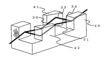
上記非対称反射とnonplanarの同時反射を組み合わせたX線干渉計の例を図10に示す。このX線干渉計は、実施の形態3の同時反射型X線干渉計と同様に、単結晶インゴットから一体で切り出した4枚の結晶プレートとその土台から構成されている。試料及び位相シフタも同様に第2プレート41と第3プレート42の間に設置する。試料を透過したX線は屈折により曲げられているので、第2プレート41に非対称反射を用いてその回折角度幅を広げればよい。しかしながら、第2プレート41のみ非対称反射としたのでは、第4プレート40上で第4ビーム33と第5ビーム34が同じ点に入射しなくなってしまう。そこで、第3プレート42にも同じ非対称因子bの非対称反射を用いることにより、第4プレート40上で第4ビーム33と第5ビーム34が同じ点に入射するようにする。
【0060】
試料の位相像は実施の形態1と同様にして取得することができる。また、X線干渉計の位置調整には実施の形態2と同様に、1/100秒の精度を持ったθ軸回転テーブル26とφ軸の回転テーブル25を用いる。X線干渉計の光軸合わせも実施の形態2と同様にして行うことができる。
以上、本実施の形態によれば、X線干渉計内のビームの回折に非対称反射を用いることにより、屈折が大きな試料においても、任意の入射X線波長を用いてビジビリティーが高く、高空間分解能の試料の位相像を取得することができる。
【0061】
〔実施の形態5〕
実施の形態3で示した同時反射型X線干渉計では、試料及び位相シフタを容易に設置できるように結晶プレートを複数に分割した。ここでは、結晶ブロックを複数個に分割することにより、より大きな試料を設置できるX線干渉計の例を示す。
【0062】
本実施の形態では、これまで1個の結晶ブロックから一体で形成されていたX線干渉計を、図11に示すように第1結晶ブロック43と第2結晶ブロック44の2個の結晶ブロックに分割する。このように構成されたX線干渉計では、第2プレート41と第3プレート42の間隔を自由に決めることができるので、より大きな試料を第1ビーム30或いは第2ビーム31の光路内に設置することができる。
【0063】
分割された結晶ブロックの相対的な位置変動は、位相の変動となって現れる。このため、精度良く位相像を観測するためには、結晶ブロック間43,44の相対的な位置変動を波長のオーダー以下に抑える必要がある。このために、干渉計全体のθ軸回転を担う第1θテーブル48、φ軸回転を担う第1φテーブル47、第2結晶のθ軸回転を行う第2θテーブル46、第2結晶のφ軸回転を行う第2φテーブル45を用いて、結晶ブロック間の位置決めを行う。各テーブルは圧電素子により駆動しても良いし、ステッピングモータなどにより駆動しても良い。
【0064】
この干渉計の調整は以下のようにして行う。
(1)結晶ブロック29のみを設置する。そして、第1θテーブル48及び第1φテーブル47を用いて、第3プレート42から出射されるビーム30および31の強度が等しくなるように、実施の形態2と同様に同時反射に使用するそれぞれの格子面となす角が等しい格子面を用いて調整する。
【0065】
(2)結晶ブロック30を設置する。第2θテーブル46及び第2φテーブル45を用い、実施の形態2と同様に同時反射に使用するそれぞれの格子面となす角が等しい格子面を用いて、結晶ブロック29に対する結晶ブロック30の位置を調整する。
【0066】
(3)以上の調整後に、干渉像の検出が可能となる。しかし、上述したように測定中に結晶ブロック43,44間の相対的な位置変動(数10pmオーダー)が生じると、第1ビーム30と第2ビーム31の間の位相が変化し、結果として干渉ビーム36の強度変動が生じてしまう。このため、測定中に干渉ビーム36の強度を一定とするように結晶ブロック間の位置を調整する制御機構を設ける。この制御機構は、干渉ビーム36を検出する2次元X線検出器の任意のピクセルからの信号強度が一定になるように第2θテーブル46及び第2φテーブル45を駆動制御するフィードバック制御機構、あるいは各テーブルの位置をモニタする高精度なレーザ干渉計を配置し、レーザ干渉計によってモニタされるテーブルの位置が一定となるように第2θテーブル46及び第2φテーブル45を駆動制御するフィードバック制御機構等によって実現することができる。
【0067】
各テーブルには非常に高い位置決め精度の他に、高い耐振動特性も要求される。そこで、これらのステージ45,46には、動摩擦係数と静止摩擦係数がほぼ等しい滑り材を使用した固体滑り機構などを用いる。試料の位相像は実施の形態1と同様の方法により取得することができる。
以上、本実施の形態によれば、サイズの大きな試料においても、任意の入射X線波長を用いてビジビリティーが高く、高空間分解能の試料の位相像を取得することができる。
【0068】
【発明の効果】
本発明によると、ブラッグケースの同時反射を利用したX線干渉計を用いることにより、ビジビリティーが高くかつ高空間分解能なX線位相像を取得できる。
【図面の簡単な説明】
【図1】 coplanarの同時反射によるビームの分割及び結合を示す図。
【図2】 nonplanarの同時反射によるビームの分割及び結合を示す図。
【図3】 coplanarの同時反射型X線干渉計を用いたX線撮像装置の構成例を示す図。
【図4】 coplanarの同時反射型X線干渉計の例を示す図。
【図5】 nonplanarの同時反射型X線干渉計を用いたX線撮像装置の構成例を示す図。
【図6】 nonplanarの同時反射型X線干渉計の例を示す図。
【図7】 nonplanarの同時反射型X線干渉計において、表面に平行な格子面により回折されたビームの光路を示す図。
【図8】結晶プレートを複数に分割したnonplanarの同時反射型X線干渉計を用いるX線撮像装置の構成例を示す図。
【図9】X線の非対称反射を示す図。
【図10】非対称反射を利用したnonplanarの同時反射型X線干渉計の例を示す図。
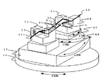
【図11】複数の結晶ブロックから構成されるnonplanarの同時反射型X線干渉計と位置調整機構を示す図。
【符号の説明】
1:入射X線、2:(n11)面による回折光、3:(n−1−1)面による回折光、4:coplanarの同時反射型X線干渉計、5:X線干渉計用位置調整機構、6:試料ホルダー、7:試料ホルダー位置決め機構、8:位相シフタ、9:位相シフタ動作機構、10:位相シフタ位置決め機構、11:X線検出器、12:制御装置、13:画像処理機構、14:表示装置、15:入射X線、16:第1プレート、17:第2プレート、18:第3プレート、19:第4プレート、20:第5プレート、21:第1ビーム、22:第2ビーム、23:干渉ビーム、24:nonplanarの同時反射型X線干渉計、25:φ軸の回転テーブル、26:θ軸回転テーブル、27:第1プレート、28:第2プレート、29:入射X線、30:第1ビーム、31:第2ビーム、32:第3ビーム、33:第4ビーム、34:第5ビーム、35:第6ビーム、36:干渉ビーム、37:第1プレート、38:第2プレート、39:第3プレート、40:第4プレート、41:非対称第2プレート、42:非対称第3プレートを複数に分割したnonplanarの同時反射型X線干渉計、43:第1結晶、44:第2結晶、45:第2φテーブル、46:第2θテーブル、47:第1φテーブル、48:第1θテーブル[0001]
BACKGROUND OF THE INVENTION
The present invention relates to an X-ray imaging apparatus, and more particularly to an X-ray imaging apparatus that inspects the inside of an object nondestructively.
[0002]
[Prior art]
As a method for inspecting the inside of an object in a non-destructive manner, X-ray imaging apparatuses that use changes in the amplitude of X-rays that occur when X-rays pass through a sample are widely used. The image acquired by this apparatus shows the X-ray absorption distribution of the sample. By the way, when the X-ray passes through the sample, the phase changes in addition to the amplitude of the X-ray. In general, the change in phase is more significant than the change in absorption. Therefore, by capturing this change, the inside of the object can be observed with high sensitivity. Examples of using this phase change include those described in JP-A-4-348262 and those described in JP-A-10-248833. In these phase-contrast X-ray imaging apparatuses, it is possible to observe a living soft tissue that has not been observed with a conventional imaging apparatus that detects a change in amplitude without contrast.
[0003]
All of the devices described in the above publications detect phase changes using an X-ray interferometer. X-ray interferometers include Bonze-Heart interferometers (such as those described in Appl. Phys. Lett. 6,155 (1965)), and this type of interferometer divided into multiple crystal blocks. Used. The Bonse-Heart interferometer is composed of a crystal block with three teeth (beam splitter, mirror, analyzer) arranged in parallel at equal intervals. Each tooth splits, reflects and combines beams using Lauecase diffraction. The incident X-ray is split into two beams by the first tooth (splitter), and the beams split by the second tooth (mirror) are diffracted and split by the third tooth (analyzer). The beams are recombined to form an interference beam.
[0004]
When the sample is placed in one optical path of the interferometer, the phase of the beam transmitted through the sample changes according to the phase distribution of the sample. For this reason, when combined with the other beam (reference wave) by the analyzer, a change in phase appears as a change in the intensity of the interference beam due to interference. However, the phase change amount due to the sample cannot be obtained with high accuracy only from this intensity change. Therefore, a phase shifter is installed in one of the optical paths of the divided beams, and a plurality of interference beam images are measured by shifting the phase of the background. Then, after the measurement, a phase image of the sample is obtained by calculation from these interference beam images.
[0005]
[Problems to be solved by the invention]
In the Laue case diffraction used for beam splitting and coupling in the above interferometer, when the incident X-ray has an angular divergence, the X-ray travels widely in the crystal (Bolman-fan effect). This spread is about 100,000 times the divergence angle of the incident beam. For this reason, even if the incident angle is slightly deviated, the optical path of the X-ray in the crystal changes greatly, so that the signal wave and the reference wave are not coupled at the same place. As a result, X-rays having a short coherent length may have reduced visibility or the beam may not interfere. Further, the X-rays incident on the sample are refracted by a slight amount due to the difference in refractive index between the sample and the surroundings. Since this refraction is not spatially uniform, the optical path in the crystal varies depending on the location. As a result, the sample image emitted from the analyzer is blurred and the spatial resolution is reduced. It was. For this reason, the spatial resolution is about 30 μm under the measurement conditions (incident X-ray wavelength 0.07 nm,
[0006]
It is an object of the present invention to obtain an X-ray phase image with high visibility and high spatial resolution by using an X-ray interferometer that combines beams by a method different from beam combining by Lauecase diffraction. The object is to provide a phase contrast X-ray imaging apparatus.
[0007]
[Means for Solving the Problems]
As described above, the visibility and spatial resolution of the conventional phase contrast X-ray imaging apparatus are caused by the use of Laue-case diffraction to combine the signal wave and the reference wave in the X-ray interferometer. . Therefore, the above-mentioned problem can be solved by using beam combination by Bragg case diffraction instead of beam combination by Laue case diffraction. However, in ordinary Bragg case diffraction, there is only one diffracted beam for one incident beam, and the beams cannot be combined. Therefore, in the present invention, the beams are combined using the simultaneous reflection of the Bragg case. Simultaneous reflection refers to a diffraction phenomenon that occurs when incident X-rays simultaneously satisfy the Bragg diffraction conditions for a plurality of grating surfaces, and the incident X-rays are diffracted by each diffraction grating surface to generate a plurality of beams. Or a plurality of incident X-rays are combined into one beam. As with normal X-ray diffraction, there are Bragg cases and Laue cases, and when the planes of incident X-rays and diffracted X-rays are all parallel (coplanar) and non-parallel (nonplanar) Differentiated. The simultaneous reflection of the Bragg case used in the present invention will be described below by distinguishing between coplanar and nonplanar.
[0008]
As an example of coplanar simultaneous reflection, simultaneous reflection of the (n11) plane and the (n-1-1) plane will be described. FIG. 1A shows the relationship between the lattice planes when the lattice plane parallel to the crystal surface is (m00). Angle θ formed by (m00) plane and (n11) plane a Is given by the following [Equation 1]. Further, the angle θ formed by the (m00) plane and the (n-1-1) plane a ′ Is similarly given by [Equation 1].
[0009]
[Expression 1]
When the crystal is rotated by θ as shown in FIG. 1, the incident angles of the
[0011]
[Expression 2]
Next, the nonplanar simultaneous reflection will be described using the (n11) plane and the (n-1-1) plane as examples. Here, it is assumed that the lattice plane parallel to the crystal surface is the (m00) plane, and the [011] plane is parallel to the xy plane. The angle formed by the (m00) plane and the (n11) plane is θ a , The angle formed by the (m00) plane and the xy plane is θ b , The unit vector n of the diffraction grating vector g on the (n11) plane is [Equation 3].
[0013]
[Equation 3]
[0014]
[Expression 4]
[0015]
[Equation 5]
[0016]
[Formula 6]
From the above, when dρ = 0, θ i = Θ i If the wavelength λ of the incident X-ray satisfies the following [Expression 7], the incident X-ray is reflected by the simultaneous reflection of the (n11) and (n-1-1) planes, and the wave vector k h X-ray and k h It can be seen that it is divided into X-rays. Where d is the lattice spacing of the (n11) plane.
[0018]
[Expression 7]
[0019]
[Equation 8]
[0020]
[Equation 9]
[0021]
[Expression 10]
[0022]
[Expression 11]
[0023]
[Expression 12]
From the above, it can be seen that in the simultaneous reflection of the (n11) and (n-1-1) planes, the diffracted light is diffracted in a symmetric direction with respect to the xz plane. Conversely, if X-rays enter from the b and b 'directions, they are diffracted by the (n11) plane and the (n-1-1) plane, respectively, as shown in FIG. And emitted in the opposite direction to a. By the way, incident X-ray k o Angle of incidence on the (n11) plane of B Is given by [Equation 14] when dρ = 0.
[0025]
[Expression 14]
In this equation, the angle θ formed by the crystal surface and the (n11) plane a Is uniquely determined, but the incident angle θ of X-rays on the crystal surface b Can take any value. Therefore, unlike coplanar simultaneous reflection, the incident angle of X-rays to the (n11) plane can be set arbitrarily, and the wavelength of incident X-rays can be made variable.
[0027]
As described above, when the simultaneous reflection of the Bragg case is used, a plurality of (two in the above example) incident beams can be combined into one beam. For this reason, there is no decrease in visibility or spatial resolution due to the Borman-Fan effect observed in Lauecase diffraction. Therefore, by using an X-ray interferometer that combines beams using this simultaneous reflection, the visibility and spatial resolution of the phase contrast X-ray imaging apparatus can be improved. The spatial resolution under frequently used measurement conditions (incident X-ray wavelength of 0.07 nm) is considered to be several microns or less, an improvement of one digit or more as compared with conventional imaging devices. As a result, it is possible to observe the state of individual cells constituting the soft tissue of the living body and to observe the cells and the organs and structures in the cells, which can be expected to be useful for elucidating various biological mechanisms.
[0028]
The technical features employed in the present invention to achieve the above object are listed below.
An X-ray imaging apparatus according to an aspect of the present invention includes a splitting element that splits an incident X-ray beam into a plurality of beams, a reflecting element that reflects the split plurality of beams, and a coupling that combines the reflected plurality of beams. Detects the element, the means for placing the sample in the optical path of one of the divided beams, the phase shifter installed in the optical path of one of the divided beams or the other beam, and the beam combined by the coupling element And a processing unit for obtaining a phase image of the sample based on the output of the X-ray detector, and simultaneous X-ray reflection is used for splitting the beam by the splitting element and for combining the beams by the combining element. It is characterized by.
[0029]
The sample and the phase shifter may be installed in separate optical paths or in the same optical path. The X-ray detector is preferably a two-dimensional X-ray detector.
The surfaces formed by the plurality of beams incident on the coupling element and the beams coupled by the coupling element can be non-parallel to each other. Further, the surfaces formed by the beam incident on the splitting element and the plurality of beams split by the splitting element can be made non-parallel to each other. According to this configuration, the wavelength of incident X-rays can be made variable.
[0030]
Asymmetric reflection may be used for reflection of the beam by the reflecting element. By using asymmetric reflection, the condition of the angle width of incident X-rays that causes diffraction can be relaxed. Further, the width of the incident beam is expanded by asymmetric reflection, and an image can be acquired with higher spatial resolution.
The dividing element, the reflecting element, and the coupling element can be set on two crystal plates that are integrally formed from a single crystal block and whose opposing faces are parallel to each other.
[0031]
At least one of the two crystal plates may be divided in a direction along the optical path of the beam. By dividing the crystal plate, the sample and the phase shifter can be easily installed.
The dividing element, the reflecting element, and the coupling element are set on a plurality of crystal plates formed integrally from a single crystal block, and the plurality of crystal plates include a first crystal plate pair whose opposing surfaces are parallel to each other, It is possible to include a second crystal plate pair whose opposing surfaces are parallel to each other and non-parallel to the opposing surfaces of the first crystal plate pair.
[0032]
The single crystal block may be divided into a plurality of blocks. By dividing the single crystal block, the degree of freedom regarding the installation of the sample and the phase shifter can be further increased.
An X-ray imaging method according to an aspect of the present invention is an X-ray imaging method using the above-described X-ray imaging apparatus, and an incident X-ray beam using a grating surface having the same angle with each grating surface used for simultaneous reflection. And the optical axis alignment of the dividing element, the reflecting element, and the coupling element.
[0033]
DETAILED DESCRIPTION OF THE INVENTION
Hereinafter, embodiments of the present invention will be described with reference to the drawings. In the drawings shown below, portions having the same function are denoted by the same reference numerals, and redundant description is omitted.
[Embodiment 1]
FIG. 3 is a configuration diagram of an example of a phase contrast X-ray imaging apparatus according to the present invention. As shown in the figure, the X-ray imaging apparatus includes a simultaneous reflection
[0034]
As the simultaneous reflection type X-ray interferometer, an interferometer (as described in FIG. 7 of Z.
[0035]
The incident X-ray 15 is split into a
[0036]
However, it is impossible to accurately detect the phase change due to the sample from one interference image, or to determine whether the phase change in the region where the interference fringes form a ring is concave or convex. Here, a phase shift distribution image is obtained from the interference pattern using a technique known as a fringe scanning method in the field of visible light interference optics (Appl. Opt., 33, 2693 (1974)). In this method, a phase shift distribution image is obtained by calculation from a plurality of interference patterns obtained by gradually changing the relative phase difference between two interfering X-ray beams. Now, assuming that M interference patterns are obtained while changing the phase difference by 2π / M, a phase shift image can be obtained by calculating the declination of the following [Equation 15].
[0037]
Therefore, the
[0038]
The
[0039]
[Expression 15]
In the coplanar simultaneous reflection, the incident angle depends on the rotation of the θ axis and the rotation of the φ axis. For this reason, it is necessary to control the rotation of both axes with sufficiently fine accuracy (about 1/100 second) than the diffraction width of simultaneous reflection. Therefore, the X-ray interferometer
As described above, according to the present embodiment, a phase image of a sample with high visibility and high spatial resolution can be obtained by using an X-ray interferometer that combines beams by simultaneous reflection of a Bragg case.
[0041]
[Embodiment 2]
Since the simultaneous reflection type X-ray interferometer used in the first embodiment uses the coplanar simultaneous reflection, the wavelength of the incident X-ray is uniquely determined by the diffraction surface of the simultaneous reflection used as described above. It will be decided. For this reason, the wavelength of the X-ray optimized for the thickness of the sample cannot be selected. Here, an example of an X-ray imaging apparatus using an X-ray interferometer that combines beams by simultaneous nonplanar reflection is shown. FIG. 5 shows the configuration of the apparatus, and FIG. 6 shows details of the X-ray interferometer. As shown in the figure, the X-ray imaging apparatus has substantially the same configuration as that of the first embodiment.
[0042]
The nonplanar simultaneous reflection type X-ray interferometer 24 of this example is also composed of a plurality of plates cut from a Si ingot and its base. As shown in FIG. 6, the X axis (direction perpendicular to the plate surface) is <1, 0, 0>, and the −Z axis is <0, 1, 1>. Here, simultaneous reflection of Si (311) and Si (3-1-1) is used. The angle θa formed between Si (311) and the crystal surface is 25.24 degrees. For example, the Bragg angle θ when the wavelength λ of incident X-rays is 0.09 nm. B Is 15.95 degrees. X-ray incident angle θ on the crystal surface b Is given by the following [Equation 16] from [Equation 14], so it is 17.69 degrees. The angle θ between the diffracted beam and the crystal surface o Is 11.15 degrees, the angle θ with the xy plane x Is 13.55 degrees.
[0043]
[Expression 16]
In FIG. 6,
[0045]
The sample is placed on the
[0046]
Even in nonplanar simultaneous reflection, the incident angle of X-rays depends on the rotation of the θ axis and the rotation of the φ axis. For this reason, it is necessary to control the rotation of both axes with sufficiently fine accuracy (about 1/100 second) than the diffraction width of simultaneous reflection. Therefore, for the position adjustment of the X-ray interferometer, the θ-axis rotary table 26 and the φ-axis rotary table 25 having an accuracy of 1/100 second are used. These stages are controlled by the
[0047]
In order to obtain simultaneous reflection, it is necessary to position (optical axis alignment) the axes of rotation of θ and φ with extremely high accuracy on the order of seconds as described above. Therefore, if the origin of the incident angle of the
[0048]
(1) The X-ray interferometer is rotated by θ to find a diffraction peak of Si (400), which is set as the origin of θ rotation.
(2) The θ axis of the X-ray interferometer is rotated 1.67 degrees from the origin.
(3) A 2-axis scan of the θ axis and the φ axis is performed to find simultaneous reflection.
The optical axis alignment of the X-ray interferometer in steps (1) to (3) is performed by the Bragg angle θ at the wavelength of the incident X-ray. c , X-ray incident angle θ to the crystal surface where simultaneous reflection occurs b Or Bragg angle θ c And θ b It is also possible to automatically perform parameters by the
[0049]
In this embodiment, Si (311) and Si (3-1-1) are used as the lattice plane for simultaneous reflection. However, other lattice planes such as (220), (202), (111), and (1- 11) or the like may be used. Even in this case, a lattice plane having the same angle with each lattice plane (for example, (422) if (220) and (202), (202) if (111) and (1-11)) is used. Thus, the interferometer can be adjusted in the same manner as described above.
Detection of the phase image of the sample can be performed in the same manner as in the first embodiment. As described above, according to the present embodiment, a phase image of a sample with high visibility and high spatial resolution can be acquired using an arbitrary incident X-ray wavelength.
[0050]
[Embodiment 3]
In the simultaneous reflection type X-ray interferometer shown in the second embodiment, since the optical paths of the
[0051]
FIG. 8 shows a configuration example of the imaging device in this embodiment. As shown in this figure, the X-ray imaging apparatus has substantially the same configuration as that of the second embodiment. As for the X-ray interferometer, the first plate of the simultaneous reflection type X-ray interferometer shown in the second embodiment is used as the
[0052]
The
[0053]
A phase image of the sample can be obtained in the same manner as in the first embodiment. Further, the position adjustment of the X-ray interferometer uses a θ-axis rotary table 26 and a φ-axis rotary table 25 having an accuracy of 1/100 second as in the second embodiment. The optical axis alignment of the X-ray interferometer can be performed in the same manner as in the second embodiment.
As described above, according to the present embodiment, a sample and a phase shifter can be easily installed, and a phase image of a sample with high visibility and high spatial resolution can be obtained using an arbitrary incident X-ray wavelength. it can.
[0054]
[Embodiment 4]
When X-rays pass through the sample, the X-rays are refracted by a very small angle due to the difference in refractive index from the surroundings. Since the angle width at which X-ray simultaneous reflection occurs is in a very narrow range of about several seconds, simultaneous reflection may not occur even when the angle changes as described above. Here, an embodiment of a simultaneous reflection type X-ray interferometer capable of widening the angle width of diffraction by using asymmetric reflection and adapting to the change in angle will be described.
Asymmetric reflection refers to diffraction in which the crystal surface and the diffraction grating surface are non-parallel as shown in FIG. Assuming that the angle between the crystal surface and the diffraction grating plane is α, the asymmetry factor b is defined by the following [Equation 17].
[0055]
[Expression 17]
[0056]
[Expression 18]
[Equation 19]
Thus, using asymmetric reflection with b <1, ω o Therefore, even if the incident angle of the beam to the crystal plate is slightly changed, diffraction can be generated. In addition, the width of the incident beam is expanded by this asymmetric reflection. As a matter of course, the image of the subject is also enlarged. Therefore, an image can be acquired with higher spatial resolution.
[0059]
An example of an X-ray interferometer that combines the asymmetric reflection and the nonplanar simultaneous reflection is shown in FIG. Similar to the simultaneous reflection X-ray interferometer of the third embodiment, this X-ray interferometer is composed of four crystal plates integrally cut from a single crystal ingot and its base. Similarly, the sample and the phase shifter are installed between the second plate 41 and the
[0060]
A phase image of the sample can be obtained in the same manner as in the first embodiment. Further, the position adjustment of the X-ray interferometer uses a θ-axis rotary table 26 and a φ-axis rotary table 25 having an accuracy of 1/100 second as in the second embodiment. The optical axis alignment of the X-ray interferometer can be performed in the same manner as in the second embodiment.
As described above, according to the present embodiment, by using asymmetric reflection for diffraction of the beam in the X-ray interferometer, even in a sample having a large refraction, visibility is high using an arbitrary incident X-ray wavelength and high spatial resolution. A phase image of the sample can be acquired.
[0061]
[Embodiment 5]
In the simultaneous reflection type X-ray interferometer shown in the third embodiment, the crystal plate is divided into a plurality of pieces so that the sample and the phase shifter can be easily installed. Here, an example of an X-ray interferometer in which a larger sample can be set by dividing the crystal block into a plurality of parts is shown.
[0062]
In the present embodiment, the X-ray interferometer that has been integrally formed from one crystal block so far is divided into two crystal blocks, a
[0063]
The relative position fluctuation of the divided crystal block appears as a phase fluctuation. For this reason, in order to observe the phase image with high accuracy, it is necessary to suppress the relative positional fluctuation between the crystal blocks 43 and 44 to be equal to or less than the wavelength order. For this purpose, the first θ table 48 responsible for the θ-axis rotation of the entire interferometer, the first φ table 47 responsible for the φ-axis rotation, the second θ table 46 that rotates the θ-axis of the second crystal, and the φ-axis rotation of the second crystal Positioning between crystal blocks is performed using the second φ table 45 to be performed. Each table may be driven by a piezoelectric element, or may be driven by a stepping motor or the like.
[0064]
The interferometer is adjusted as follows.
(1) Only the
[0065]
(2) The
[0066]
(3) After the above adjustment, the interference image can be detected. However, as described above, if a relative positional variation (in the order of several tens of pm) between the crystal blocks 43 and 44 occurs during the measurement, the phase between the
[0067]
Each table is required to have high vibration resistance in addition to extremely high positioning accuracy. Therefore, a solid sliding mechanism using a sliding material having a kinetic friction coefficient and a static friction coefficient substantially equal is used for these stages 45 and 46. The phase image of the sample can be acquired by the same method as in the first embodiment.
As described above, according to the present embodiment, even in a large-sized sample, a phase image of a sample with high visibility and high spatial resolution can be obtained using an arbitrary incident X-ray wavelength.
[0068]
【The invention's effect】
According to the present invention, an X-ray phase image with high visibility and high spatial resolution can be acquired by using an X-ray interferometer using simultaneous reflection of a Bragg case.
[Brief description of the drawings]
FIG. 1 shows beam splitting and combining by coplanar simultaneous reflection.
FIG. 2 is a diagram showing beam splitting and combining by nonplanar simultaneous reflection.
FIG. 3 is a diagram illustrating a configuration example of an X-ray imaging apparatus using a coplanar simultaneous reflection X-ray interferometer.
FIG. 4 is a diagram showing an example of a coplanar simultaneous reflection type X-ray interferometer.
FIG. 5 is a diagram showing a configuration example of an X-ray imaging apparatus using a nonplanar simultaneous reflection type X-ray interferometer.
FIG. 6 is a diagram showing an example of a nonplanar simultaneous reflection type X-ray interferometer.
FIG. 7 is a diagram showing an optical path of a beam diffracted by a grating plane parallel to the surface in a nonplanar simultaneous reflection type X-ray interferometer.
FIG. 8 is a diagram showing a configuration example of an X-ray imaging apparatus using a nonplanar simultaneous reflection X-ray interferometer in which a crystal plate is divided into a plurality of parts.
FIG. 9 is a view showing asymmetric reflection of X-rays.
FIG. 10 is a diagram showing an example of a nonplanar simultaneous reflection type X-ray interferometer using asymmetric reflection.
FIG. 11 is a diagram showing a nonplanar simultaneous reflection X-ray interferometer and a position adjustment mechanism composed of a plurality of crystal blocks.
[Explanation of symbols]
1: incident X-ray, 2: diffracted light by (n11) plane, 3: diffracted light by (n-1-1) plane, 4: coplanar simultaneous reflection type X-ray interferometer, 5: position for X-ray interferometer Adjustment mechanism, 6: Sample holder, 7: Sample holder positioning mechanism, 8: Phase shifter, 9: Phase shifter operating mechanism, 10: Phase shifter positioning mechanism, 11: X-ray detector, 12: Controller, 13: Image processing Mechanism: 14: display device, 15: incident X-ray, 16: first plate, 17: second plate, 18: third plate, 19: fourth plate, 20: fifth plate, 21: first beam, 22 : Second beam, 23: interference beam, 24: nonplanar simultaneous reflection type X-ray interferometer, 25: φ axis rotary table, 26: θ axis rotary table, 27: first plate, 28: second plate, 29 : Incident X-ray, 30: first beam, 31: first Beam: 32: third beam, 33: fourth beam, 34: fifth beam, 35: sixth beam, 36: interference beam, 37: first plate, 38: second plate, 39: third plate, 40 : Fourth plate, 41: asymmetric second plate, 42: nonplanar simultaneous reflection X-ray interferometer obtained by dividing asymmetric third plate into a plurality, 43: first crystal, 44: second crystal, 45: second φ table , 46: second θ table, 47: first φ table, 48: first θ table
Claims (5)
前記分割素子によるビームの分割及び前記結合素子によるビームの結合にX線の同時反射を用いることを特徴とするX線撮像装置。A splitting element that splits an incident X-ray beam into a plurality of beams, a reflecting element that reflects the split plurality of beams, a coupling element that combines the reflected plurality of beams, and an optical path of the split one beam Means for placing a sample therein, a phase shifter placed in the optical path of one of the divided beams or the other beam, an X-ray detector for detecting the beam combined by the coupling element, and the X A processing unit for obtaining a phase image of the sample based on the output of the line detector,
An X-ray imaging apparatus using simultaneous X-ray reflection for beam splitting by the splitting element and beam combining by the coupling element.
Priority Applications (1)
| Application Number | Priority Date | Filing Date | Title |
|---|---|---|---|
| JP2000269214A JP3689623B2 (en) | 2000-09-05 | 2000-09-05 | X-ray imaging device |
Applications Claiming Priority (1)
| Application Number | Priority Date | Filing Date | Title |
|---|---|---|---|
| JP2000269214A JP3689623B2 (en) | 2000-09-05 | 2000-09-05 | X-ray imaging device |
Publications (2)
| Publication Number | Publication Date |
|---|---|
| JP2002082072A JP2002082072A (en) | 2002-03-22 |
| JP3689623B2 true JP3689623B2 (en) | 2005-08-31 |
Family
ID=18755861
Family Applications (1)
| Application Number | Title | Priority Date | Filing Date |
|---|---|---|---|
| JP2000269214A Expired - Fee Related JP3689623B2 (en) | 2000-09-05 | 2000-09-05 | X-ray imaging device |
Country Status (1)
| Country | Link |
|---|---|
| JP (1) | JP3689623B2 (en) |
Cited By (1)
| Publication number | Priority date | Publication date | Assignee | Title |
|---|---|---|---|---|
| JP2005152500A (en) * | 2003-11-28 | 2005-06-16 | Hitachi Ltd | X-ray imaging apparatus and imaging method |
Families Citing this family (4)
| Publication number | Priority date | Publication date | Assignee | Title |
|---|---|---|---|---|
| JP4676244B2 (en) * | 2005-05-13 | 2011-04-27 | 株式会社日立製作所 | X-ray imaging device |
| WO2010143263A1 (en) * | 2009-06-09 | 2010-12-16 | 株式会社日立製作所 | Fourier transform x-ray spectroscope |
| CN109827976B (en) * | 2019-03-14 | 2024-01-05 | 中国科学院上海应用物理研究所 | Optical system for on-line observation and adjustment of X-ray beam and sample |
| TWI906841B (en) * | 2024-04-26 | 2025-12-01 | 奈視科技股份有限公司 | X-ray reflection analysis system applying multiple x-ray beams |
-
2000
- 2000-09-05 JP JP2000269214A patent/JP3689623B2/en not_active Expired - Fee Related
Cited By (1)
| Publication number | Priority date | Publication date | Assignee | Title |
|---|---|---|---|---|
| JP2005152500A (en) * | 2003-11-28 | 2005-06-16 | Hitachi Ltd | X-ray imaging apparatus and imaging method |
Also Published As
| Publication number | Publication date |
|---|---|
| JP2002082072A (en) | 2002-03-22 |
Similar Documents
| Publication | Publication Date | Title |
|---|---|---|
| US5469259A (en) | Inspection interferometer with scanning autofocus, and phase angle control features | |
| US10451402B2 (en) | Single shot full-field reflection phase microscopy | |
| EP1875162B1 (en) | Determining positional error of an optical component using structured light patterns | |
| JP4898869B2 (en) | Method and apparatus for characterization of angle resolved spectroscopic lithography | |
| EP2899495A1 (en) | Interferometer and phase shift amount measuring apparatus | |
| KR20100134609A (en) | Apparatus and method for measuring the surface shape of an object | |
| US11187518B2 (en) | Method and apparatus for super-resolution optical metrology | |
| KR20090113895A (en) | Defect measuring device of glass sheet | |
| KR20120095317A (en) | Optical apparatus, method of scanning, lithographic apparatus and device manufacturing method | |
| JP7326292B2 (en) | Apparatus and method for determining the position of a target structure on a substrate | |
| JP4862051B2 (en) | Three-wave transverse shear compact achromatic optical interferometer | |
| TW479127B (en) | Method and device for measuring thickness of test object | |
| JP5349739B2 (en) | Interferometer and interferometer calibration method | |
| JP3689623B2 (en) | X-ray imaging device | |
| US20050117699A1 (en) | X-ray imaging apparatus and x-ray imaging method | |
| JP3714853B2 (en) | Planar shape measuring method in phase shift interference fringe simultaneous imaging device | |
| JP4427632B2 (en) | High-precision 3D shape measuring device | |
| Misumi et al. | 25 nm pitch comparison between a traceable x-ray diffractometer and a metrological atomic force microscope | |
| US6804009B2 (en) | Wollaston prism phase-stepping point diffraction interferometer and method | |
| JP4015394B2 (en) | X-ray imaging | |
| JPH07280535A (en) | Three-dimensional shape measuring device | |
| DE102018112204A1 (en) | Displacement detection device | |
| JP2000249510A (en) | Shearing interferometer, refractive index distribution measuring device provided with the interferometer, and method of measuring refractive index distribution | |
| JP2005326192A (en) | 3D shape measuring device | |
| US12467737B1 (en) | Self-referencing interferometric microscope |
Legal Events
| Date | Code | Title | Description |
|---|---|---|---|
| A977 | Report on retrieval |
Free format text: JAPANESE INTERMEDIATE CODE: A971007 Effective date: 20050520 |
|
| TRDD | Decision of grant or rejection written | ||
| A01 | Written decision to grant a patent or to grant a registration (utility model) |
Free format text: JAPANESE INTERMEDIATE CODE: A01 Effective date: 20050524 |
|
| A61 | First payment of annual fees (during grant procedure) |
Free format text: JAPANESE INTERMEDIATE CODE: A61 Effective date: 20050613 |
|
| FPAY | Renewal fee payment (event date is renewal date of database) |
Free format text: PAYMENT UNTIL: 20080617 Year of fee payment: 3 |
|
| FPAY | Renewal fee payment (event date is renewal date of database) |
Free format text: PAYMENT UNTIL: 20090617 Year of fee payment: 4 |
|
| FPAY | Renewal fee payment (event date is renewal date of database) |
Free format text: PAYMENT UNTIL: 20090617 Year of fee payment: 4 |
|
| FPAY | Renewal fee payment (event date is renewal date of database) |
Free format text: PAYMENT UNTIL: 20100617 Year of fee payment: 5 |
|
| FPAY | Renewal fee payment (event date is renewal date of database) |
Free format text: PAYMENT UNTIL: 20100617 Year of fee payment: 5 |
|
| FPAY | Renewal fee payment (event date is renewal date of database) |
Free format text: PAYMENT UNTIL: 20110617 Year of fee payment: 6 |
|
| FPAY | Renewal fee payment (event date is renewal date of database) |
Free format text: PAYMENT UNTIL: 20110617 Year of fee payment: 6 |
|
| FPAY | Renewal fee payment (event date is renewal date of database) |
Free format text: PAYMENT UNTIL: 20120617 Year of fee payment: 7 |
|
| LAPS | Cancellation because of no payment of annual fees |