JP3701112B2 - Concrete block connector and method of using the same - Google Patents
Concrete block connector and method of using the same Download PDFInfo
- Publication number
- JP3701112B2 JP3701112B2 JP32851297A JP32851297A JP3701112B2 JP 3701112 B2 JP3701112 B2 JP 3701112B2 JP 32851297 A JP32851297 A JP 32851297A JP 32851297 A JP32851297 A JP 32851297A JP 3701112 B2 JP3701112 B2 JP 3701112B2
- Authority
- JP
- Japan
- Prior art keywords
- shaped
- concrete block
- loop
- block
- pair
- Prior art date
- Legal status (The legal status is an assumption and is not a legal conclusion. Google has not performed a legal analysis and makes no representation as to the accuracy of the status listed.)
- Expired - Lifetime
Links
- 238000000034 method Methods 0.000 title description 7
- 230000003014 reinforcing effect Effects 0.000 claims description 16
- 230000000630 rising effect Effects 0.000 claims description 8
- 230000008878 coupling Effects 0.000 claims 1
- 238000010168 coupling process Methods 0.000 claims 1
- 238000005859 coupling reaction Methods 0.000 claims 1
- 238000003466 welding Methods 0.000 description 3
- 230000000694 effects Effects 0.000 description 2
- 230000001788 irregular Effects 0.000 description 2
- 238000005452 bending Methods 0.000 description 1
- 238000010276 construction Methods 0.000 description 1
- 238000010586 diagram Methods 0.000 description 1
- 238000005516 engineering process Methods 0.000 description 1
- 238000003780 insertion Methods 0.000 description 1
- 230000037431 insertion Effects 0.000 description 1
- 238000004519 manufacturing process Methods 0.000 description 1
- 230000002787 reinforcement Effects 0.000 description 1
Images


Landscapes
- Pit Excavations, Shoring, Fill Or Stabilisation Of Slopes (AREA)
- Road Paving Structures (AREA)
- Revetment (AREA)
Description
【0001】
【発明の属する技術分野】
本発明は、法面保護、護岸、路面被覆等に用いる比較的厚さの薄いコンクリートブロックを隅角部で連結するコンクリートブロックの連結具及びその使用方法に関する。
【0002】
【従来の技術】
コンクリートブロックから鉄筋を突出させておき、この鉄筋を連結してコンクリートブロックを一体化する場合、突出鉄筋同士を溶接接合するか又はループ状に突出した鉄筋を連結具で結合するのが一般的である。溶接は、天候に支配されたり、溶接技術者を要するなどの問題がある。ループ状に突出させる鉄筋を結合するには、鉄筋のループの面をコンクリートブロックの表面に対して直角にしてブロックの側面に突出させ、隣接ブロックの側面から突出したループと対向させ、ループ内をシャックル又は円環状綴じボルトで綴じ合わせることが通常行われている。図5はこのようなコンクリートブロックの隅角部の結合を示す平面図である。4個のブロック100a、100b、100c、100dの隅角部からそれぞれブロックの面に直角なループ鉄筋102a、102b、102c、102dが突設されている。環状クリップ103が各ループ鉄筋を縫い合わせている。
【0003】
このようなブロックの表面に直交するループの面を有する鉄筋は、表面積が比較的大きく厚さが薄いコンクリートブロックでは制約され、コンクリート中から突出させることが強度上や製造技術上好ましくない。そこで、厚さの薄いコンクリートブロックでは、ループがコンクリートブロック表面と平行な面内にあるように設けられる。
【0004】
このようなコンクリートブロックの隅角部の突出鉄筋のループを綴じ合わせるにはシャックル等では不適当である。そこで、三次元的に湾曲したU字ボルトとプレートとを組み合わせた連結具で連結する連結方法がある(例えば、特許文献1参照)。この連結具は三次元的に形成され、両ねじのUボルトをU字の軸を含む面をU字形に湾曲させた形状を有するものであるため、ループ鉄筋が不揃いであったり、不整形である時には連結具を挿入装着する自由度が小さく、施工が容易でなく、また突出鉄筋同士を遊びがないように強固に緊密に結合することはできなかった。
【0005】
【特許文献1】
特公平7−86215号公報
【0006】
【発明が解決しようとする課題】
本発明は上記問題点を解決した技術を提供するもので、比較的厚さの薄いコンクリートブロックの隅角部の突出鉄筋を容易に緊密に連結することができるコンクリートブロックの連結具及びその使用方法を開発し、これを提供することを目的とするものである。
【0007】
【課題を解決するための手段】
本発明は、上記問題点を解決するためになされたもので、次の技術手段を講じたことを特徴とする。
【0008】
本発明は、U字ボルトの立ち上がり部の一方には他のU字部材のねじ部が挿通され締付ナットが着座する座を備え、立ち上がり部の他方にはU字ボルトのU字を含む面から側方に延出し、延出端にねじ部が形成されたU字部材の一双の組合わせからなることを特徴とする。この連結具は、ねじの締付け方向がループ鉄筋同士を引き寄せる方向に緊密に締めつける作用がある。
【0009】
この連結具は一双の部材からなり、各部材は1本の線材又は棒材の単純な形状の曲がり部材であり、ループ鉄筋に自由に挿通することができるから、4個のコンクリートブロックの隅角部の4個のループ突出鉄筋が不揃いであったり変形していても、これらを容易に縫い合わせて結合することができる。
【0010】
前記一双のU字部材が同形であるものは1種類の部材でよく、前記一双のU字部材の延出部が互いに左右勝手違いであるものでは、2種類の部材となるが部材が互いにクロスして強固に結合することができる。また一双の部材を組合わせて締付けナットで締めるので、ループ鉄筋を緊密に締めつけることができる。
【0011】
さらにコンクリートブロックが地盤沈下等によって不陸が生ずるような場合に連結部に屈撓性を付与することができる。
【0012】
上記コンクリートブロックの連結具の使用方法は次のとおりである。
【0013】
連結すべきコンクリートブロックの隅角部の角切りした部分から突出され、ブロックの表面と平行な同一平面内でU字ループを形成する4個のU字鉄筋を対向させてコンクリートブロックを敷並べ、上記一双のコンクリートブロックの連結具をこれらのU字ループ鉄筋を縫い合わせるように上下に貫通して挿通し、一双のU字ボルトのそれぞれの座の孔に他のU字ボルトのねじ部を挿通し、それぞれのねじにナットを螺合して組み立て、ブロックを連結する。組み立てられた連結具は、4つのそれぞれのループを貫通し、隣接するループの上面と下面の何れかで互いに連結されている。ねじ部は他の部材の座の孔に挿通されるが、その位置は互いに任意の位置に定めることができるから、組立の自由度が大きい。またナットは、それぞれの座に安定的に着座し、しっかりと締付けることができる。
【0014】
【発明の実施の形態】
以下、図面を参照して本発明のコンクリートブロックの連結具及びその使用方法の実施の形態を説明する。
【0015】
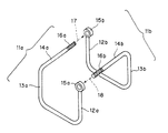
図1は、実施例のU字部材11a、11bからなる連結具である。この実施例では、U字形の立ち上がり部の一方12a、12bに座15a、15bを取付け、他方の立ち上がり部13a、13bの先端を側方に曲げて延出させ延出部14a、14bの先端にねじ部16a、16bを設けたものである。
【0016】
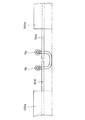
図2は、ブロック100a、100b、100c、100dの隅角部のループ鉄筋101a、101b、101c、101dにU字部材11a、11bからなるコンクリートブロックの連結具を組込んだ状態を示す平面図、図3は図2の側面図、図4は図2の正面図を示したものである。
【0017】
【発明の効果】
本発明のコンクリートブロックの連結具は以上のように構成されているので、コンクリートブロックの隅角部に突出したループ鉄筋に挿通するとき自由度が大きく容易に挿通することができ、挿通後締付ナットを締めつけることによりループ鉄筋とU路部材との隙間がなくなるように緊密に組立てることができる。その結果、コンクリートブロック同士の連結が確実になる。またこのとき、ループ鉄筋同士は互いにヒンジとして作動することは確保され自由に動き得るので、ブロック同士の屈撓性は確保される。
【図面の簡単な説明】
【図1】実施例の連結具部材の斜視図である。
【図2】図1の組立平面図である。
【図3】図2の側面図である。
【図4】図2の正面図である。
【図5】従来技術の説明図である。
【符号の説明】
11a、11b U字部材
12a、12b 立ち上がり部
13a、13b 立ち上がり部
14a、14b 延出部
15a、15b 座
16a、16b ねじ部
100a、100b、100c、100d ブロック
101a、101b、101c、101d ループ鉄筋[0001]
BACKGROUND OF THE INVENTION
The present invention relates to a concrete block connector for connecting a relatively thin concrete block used for slope protection, revetment, road surface covering, and the like at a corner, and a method of using the same.
[0002]
[Prior art]
When reinforcing bars are protruded from a concrete block and these reinforcing bars are connected to integrate the concrete block, it is common to connect the protruding reinforcing bars together by welding, or to connect the reinforcing bars protruding like a loop with a connector. is there. Welding has problems such as being controlled by the weather and requiring a welding engineer. To connect a reinforcing bar that protrudes in a loop shape, make the loop surface of the reinforcing bar perpendicular to the surface of the concrete block, project it to the side of the block, face the loop protruding from the side of the adjacent block, and inside the loop It is common practice to bind with a shackle or an annular binding bolt. FIG. 5 is a plan view showing the connection of the corners of such a concrete block. Loop rebars 102a, 102b, 102c, and 102d that are perpendicular to the surfaces of the blocks protrude from the corners of the four
[0003]
Such a reinforcing bar having a loop surface orthogonal to the surface of the block is restricted by a concrete block having a relatively large surface area and a small thickness, and it is not preferable in terms of strength and manufacturing technology to protrude from the concrete. Therefore, in the concrete block having a small thickness, the loop is provided in a plane parallel to the concrete block surface.
[0004]
A shackle or the like is not suitable for binding the protruding reinforcing bar loops at the corners of the concrete block. Therefore, there is a connection method in which a U-bolt that is curved three-dimensionally and a plate are connected by a connecting tool (see, for example, Patent Document 1). This connector is formed three-dimensionally and has a U-bolt of both screws curved in a U-shaped surface including the U-shaped shaft, so that the loop rebar is uneven or irregular. In some cases, the degree of freedom for inserting and mounting the connector was small, the construction was not easy, and the protruding reinforcing bars could not be firmly and tightly joined together so that there was no play.
[0005]
[Patent Document 1]
Japanese Examined Patent Publication No. 7-86215 [0006]
[Problems to be solved by the invention]
The present invention provides a technique that solves the above-mentioned problems, and a concrete block connector capable of easily and tightly connecting protruding reinforcing bars at corners of a relatively thin concrete block, and a method of using the same. Is intended to develop and provide this.
[0007]
[Means for Solving the Problems]
The present invention has been made to solve the above problems, and is characterized by taking the following technical means.
[0008]
The present invention includes a seat on which one of the rising portions of the U-bolt is inserted with a threaded portion of another U-shaped member and on which a tightening nut is seated, and the other of the rising portions includes the U-shape of the U-shaped bolt. It is characterized by comprising a pair of U-shaped members that extend laterally from the side and have a threaded portion formed at the extended end. This connector has an effect of tightening tightly in a direction in which the screw tightening direction pulls the loop reinforcing bars together.
[0009]
This connector consists of a pair of members, and each member is a bending member with a simple shape of one wire or bar, and can be freely inserted into the loop rebar, so the corner angles of the four concrete blocks Even if the four loop protruding reinforcing bars of the part are irregular or deformed, they can be easily sewn and combined.
[0010]
If the pair of U-shaped members have the same shape, one type of member may be used, and if the extended portions of the pair of U-shaped members are different from each other, they are two types of members, but the members cross each other. And can be firmly bonded. Moreover, since a pair of members are combined and tightened with a tightening nut, the loop rebar can be tightened tightly.
[0011]
Furthermore, when the concrete block becomes uneven due to ground subsidence or the like, it is possible to impart flexibility to the connecting portion.
[0012]
The method of using the concrete block connector is as follows.
[0013]
The concrete blocks are laid out with four U-shaped reinforcing bars facing each other and forming U-shaped loops in the same plane parallel to the surface of the blocks, which protrude from the corners of the concrete blocks to be connected. The above-mentioned pair of concrete block connectors are inserted through the U-shaped loop reinforcing bars so as to sew together, and the thread portions of the other U-bolts are inserted into the holes of the seats of the pair of U-bolts. The nuts are screwed into the respective screws and assembled to connect the blocks. The assembled connector passes through each of the four loops and is connected to each other on either the upper surface or the lower surface of the adjacent loop. Although the threaded portion is inserted into the hole of the seat of the other member, the positions thereof can be set at arbitrary positions with each other, so that the degree of freedom of assembly is great. Also, the nut can be seated stably in each seat and tightened securely.
[0014]
DETAILED DESCRIPTION OF THE INVENTION
Embodiments of a concrete block connector and a method of using the same according to the present invention will be described below with reference to the drawings.
[0015]
FIG. 1 shows a connector composed of U-shaped
[0016]
FIG. 2 is a plan view showing a state in which a concrete block connector made up of U-shaped
[0017]
【The invention's effect】
Since the concrete block connector of the present invention is configured as described above, it can be easily inserted with a large degree of freedom when inserted into a loop rebar protruding from the corner of the concrete block, and tightened after insertion. By tightening the nut, it can be assembled tightly so that there is no gap between the loop rebar and the U-path member. As a result, the connection between the concrete blocks is ensured. At this time, it is ensured that the loop reinforcing bars act as hinges and can move freely, so that the flexibility between the blocks is ensured.
[Brief description of the drawings]
FIG. 1 is a perspective view of a connector member according to an embodiment.
2 is an assembly plan view of FIG. 1. FIG.
FIG. 3 is a side view of FIG. 2;
4 is a front view of FIG. 2;
FIG. 5 is an explanatory diagram of a prior art.
[Explanation of symbols]
11a, 11b
Claims (2)
Priority Applications (1)
| Application Number | Priority Date | Filing Date | Title |
|---|---|---|---|
| JP32851297A JP3701112B2 (en) | 1997-11-28 | 1997-11-28 | Concrete block connector and method of using the same |
Applications Claiming Priority (1)
| Application Number | Priority Date | Filing Date | Title |
|---|---|---|---|
| JP32851297A JP3701112B2 (en) | 1997-11-28 | 1997-11-28 | Concrete block connector and method of using the same |
Publications (2)
| Publication Number | Publication Date |
|---|---|
| JPH11158878A JPH11158878A (en) | 1999-06-15 |
| JP3701112B2 true JP3701112B2 (en) | 2005-09-28 |
Family
ID=18211116
Family Applications (1)
| Application Number | Title | Priority Date | Filing Date |
|---|---|---|---|
| JP32851297A Expired - Lifetime JP3701112B2 (en) | 1997-11-28 | 1997-11-28 | Concrete block connector and method of using the same |
Country Status (1)
| Country | Link |
|---|---|
| JP (1) | JP3701112B2 (en) |
Families Citing this family (1)
| Publication number | Priority date | Publication date | Assignee | Title |
|---|---|---|---|---|
| CN103122619B (en) * | 2013-02-25 | 2015-06-03 | 金发科技股份有限公司 | Protective hooking body |
-
1997
- 1997-11-28 JP JP32851297A patent/JP3701112B2/en not_active Expired - Lifetime
Also Published As
| Publication number | Publication date |
|---|---|
| JPH11158878A (en) | 1999-06-15 |
Similar Documents
| Publication | Publication Date | Title |
|---|---|---|
| US5525014A (en) | Horizontally-yielding earth stabilizing structure | |
| US6343449B1 (en) | Tension strap connector assembly | |
| US20090308017A1 (en) | Reinforcing bar anchorage | |
| US6571528B1 (en) | Mechanical connector between headed studs and reinforcing steel | |
| JP3701112B2 (en) | Concrete block connector and method of using the same | |
| JP2003184223A (en) | Fastener for reinforcements | |
| JP4024688B2 (en) | Wire mesh fixing bracket | |
| JPH04108944A (en) | Constitution of bar arrangement of reinforced concrete construction | |
| PL169144B1 (en) | Connector for connecting construction elements PL | |
| JP3902451B2 (en) | Structure of fastener and its buried setting part | |
| JP4281886B2 (en) | High load rebar clip | |
| JPH10231585A (en) | Shear reinforcement | |
| JPH0786215B2 (en) | How to connect blocks | |
| JP2004011672A (en) | Wire connecting tool, wire connecting apparatus and wire connecting method | |
| JP2648085B2 (en) | Reinforced joints for reinforced concrete buildings | |
| KR102889864B1 (en) | Anti-crack brackets and anti-crack devices | |
| JPS6219749Y2 (en) | ||
| JPH11315526A (en) | Joint method of concrete block | |
| KR200156121Y1 (en) | Bending Ceiling Bar Coupler | |
| JPH0715938Y2 (en) | Reinforcing bar connector | |
| JP2003301561A (en) | Reinforcement joint | |
| JP2002129706A (en) | Holding jig for lattice frame assembling rod such as reinforcement or the like | |
| JPS6032206Y2 (en) | Beam joint structure | |
| JP2000234418A (en) | Holding jig of lattice frame assembling rod-like body for reinforcing bar or the like | |
| JP2512780Y2 (en) | Concrete block connecting member |
Legal Events
| Date | Code | Title | Description |
|---|---|---|---|
| A977 | Report on retrieval |
Free format text: JAPANESE INTERMEDIATE CODE: A971007 Effective date: 20050628 |
|
| TRDD | Decision of grant or rejection written | ||
| A01 | Written decision to grant a patent or to grant a registration (utility model) |
Free format text: JAPANESE INTERMEDIATE CODE: A01 Effective date: 20050705 |
|
| A61 | First payment of annual fees (during grant procedure) |
Free format text: JAPANESE INTERMEDIATE CODE: A61 Effective date: 20050712 |
|
| R150 | Certificate of patent or registration of utility model |
Free format text: JAPANESE INTERMEDIATE CODE: R150 |
|
| S111 | Request for change of ownership or part of ownership |
Free format text: JAPANESE INTERMEDIATE CODE: R313113 |
|
| FPAY | Renewal fee payment (event date is renewal date of database) |
Free format text: PAYMENT UNTIL: 20080722 Year of fee payment: 3 |
|
| R350 | Written notification of registration of transfer |
Free format text: JAPANESE INTERMEDIATE CODE: R350 |
|
| FPAY | Renewal fee payment (event date is renewal date of database) |
Free format text: PAYMENT UNTIL: 20090722 Year of fee payment: 4 |
|
| FPAY | Renewal fee payment (event date is renewal date of database) |
Free format text: PAYMENT UNTIL: 20100722 Year of fee payment: 5 |