JP3710109B2 - Repeater in fire alarm equipment - Google Patents
Repeater in fire alarm equipment Download PDFInfo
- Publication number
- JP3710109B2 JP3710109B2 JP10443896A JP10443896A JP3710109B2 JP 3710109 B2 JP3710109 B2 JP 3710109B2 JP 10443896 A JP10443896 A JP 10443896A JP 10443896 A JP10443896 A JP 10443896A JP 3710109 B2 JP3710109 B2 JP 3710109B2
- Authority
- JP
- Japan
- Prior art keywords
- fire
- repeater
- fire detector
- receiver
- failure
- Prior art date
- Legal status (The legal status is an assumption and is not a legal conclusion. Google has not performed a legal analysis and makes no representation as to the accuracy of the status listed.)
- Expired - Fee Related
Links
- 238000012360 testing method Methods 0.000 claims description 47
- 230000006870 function Effects 0.000 claims description 37
- 230000005540 biological transmission Effects 0.000 claims description 19
- 238000001514 detection method Methods 0.000 claims description 16
- 238000006243 chemical reaction Methods 0.000 claims 1
- 238000010586 diagram Methods 0.000 description 10
- 230000008054 signal transmission Effects 0.000 description 6
- 238000000034 method Methods 0.000 description 4
- 230000000694 effects Effects 0.000 description 2
- 238000007689 inspection Methods 0.000 description 1
Images


Landscapes
- Alarm Systems (AREA)
- Fire Alarms (AREA)
Description
【0001】
【発明の属する技術分野】
本発明は、火災受信機と火災感知器との間に接続される中継器に関する。
【0002】
【従来の技術】
従来の火災報知設備において、火災受信機に接続されている火災感知器が正常に機能しているか否かの自動試験を行う場合、接続される火災感知器の全てを自動試験の対象にしている。つまり、自動試験機能を有する火災感知器が伝送の回線を介して、R型火災受信機に接続され、上記自動試験機能付き火災感知器の全てに、互いに異なる固有のアドレスを付与し、このアドレスを介して、R型火災受信機と交信し、上記自動試験機能付き火災感知器のいずれかが故障信号を発生すると、その故障した火災感知器がどれであるかをR型火災受信機が個別に識別することができる。
【0003】
図6は、従来の火災報知設備を示すブロック図である。
【0004】
上記の場合、R型火災受信機10Rに第1の伝送の回線20R1が接続され、付与可能なアドレス数よりも多くの自動試験機能付き火災感知器を接続したい場合には、この伝送の回線20R1に自動試験機能付火災感知器SA1、SA2、……の他に、中継器CA0を接続し、これら自動試験機能付火災感知器SA1、SA2、……、中継器CA0のそれぞれに独自のアドレスを付与し、中継器CA0に、第2の伝送の回線20R2を介して、複数の自動試験機能付き火災感知器SA11、SA12、……を接続し、これら火災感知器SA11、SA12、……の間で互いに異なるアドレス(火災感知器SA1、SA2等に付与しているアドレスと重複するアドレスを付与してもよい)を付与することによって、火災感知器を増設可能にしている。
【0005】
【発明が解決しようとする課題】
ところで、監視区域には、プライバシーの関係上、必要以上に外部の人が入ることを好まない領域(たとえば社長室)、また人の立ち入りが危険若しくは困難な領域があり、このような領域には通常の火災感知器を設置しても試験(点検)を行いにくいことから、自動試験機能付機の火災感知器が設置されることが多い。したがって、プライバシー保護を必要とする領域が一部分である場合には、火災報知設備に設けられている火災感知器の一部にのみ、自動試験機能が付与されている火災感知器を接続すれば足り、このようにすれば、プライバシー保護を必要とする領域以外の領域では安価な一般型の火災感知器を使用できるので、火災報知設備全体のコストが低くなる。
【0006】
しかし、火災受信機に接続する火災感知器のうちで1つでもアドレスを付与し、ポーリングによってその火災感知器と交信しようとした場合には、火災受信機としてR型火災受信機を使用する必要があるので、火災受信機自体のコストを下げることができないという問題がある。換言すれば、R型火災受信機が高価であることから、たとえ一部の火災感知器にのみ自動試験機能を付与するようにしても、全体としては火災報知設備が高価であるという問題がある。
【0007】
本発明は、火災報知設備における多数の火災感知器のうちの一部の火災感知器にのみ自動試験機能を付与する場合、P型火災受信機を使用しても、火災感知、故障検出することができる火災報知設備における中継器を提供することを目的とするものである。
【0008】
【課題を解決するための手段】
本発明は、互いに異なるアドレスが付与され自動試験機能を有する複数の火災感知器と伝送の回線を経由して接続され、上記アドレスを介して上記各火災感知器と交信する送受信回路と、上記火災感知器から火災信号、故障信号を検出する検出手段と、P型回線を経由してP型火災受信機と接続される2つの受信機側端子と、上記検出手段が火災信号を検出したときに、上記2つの受信機側端子間のインピーダンス値を火災検出用インピーダンス値に変化させ、一方、上記検出手段が上記故障信号を検出したときに、上記2つの受信機側端子間のインピーダンス値を故障検出用インピーダンス値に変化するインピーダンス変化手段と、上記検出手段が上記故障信号を検出したときに、上記複数の火災感知器の少なくとも1つが故障していることを示す故障表示を行う故障表示手段とを有する中継器である。
【0009】
【発明の実施の形態および実施例】
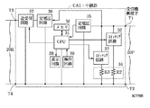
図1は、本発明の一実施例である火災報知設備における中継器CA1と、この周辺を示すブロック図である。
【0010】
この実施例では、P型火災受信機10Pに、2つのP型回線20P、21Pが接続され、P型回線20Pに、一般型火災感知器SE1、SE2、SE3、SE4、……とともに、中継器CA1が接続され、伝送の回線20Rを介して、中継器CA1に自動試験機能付き火災感知器SA1、SA2、SA3、……が接続されている。P型回線21Pには、一般型火災感知器SE11、SE12、SE13、……が接続されている。
【0011】
中継器CA1は、互いに異なるアドレスが付与される自動試験機能を有する複数の火災感知器SA1〜SA3と伝送の回線20Rを経由して接続され、上記アドレスを介して上記各火災感知器SA1〜SA3と交信するとともに、P型回線20Pを介して、P型火災受信機10Pに火災信号、故障信号を送出するものである。
【0012】
自動試験機能付き火災感知器SA1は、独自のアドレスが付与され、自身で故障検出を行うことができ、火災信号、故障信号を中継器CA1に送出するものである。自動試験機能付き火災感知器SA2、SA3、……も、自動試験機能付き火災感知器SA1と同様のものである。
【0013】
なお、自動試験には、次の2つの方法があり、本発明においては、どちらの方法を使用しても構わない。1つ目の方法は、火災感知器SA1〜SA3から送出される信号のアナログ量を常時監視し、そのアナログ量が所定値から外れると、故障と判断するものであり、2つ目の方法は、中継器に設置された試験スイッチをONさせることによって、火災検出回路に火災時と同じ状態を疑似的につくるもので、そのときに火災信号が送出されればその火災感知器の機能が正常と判断するものである。
【0014】
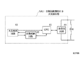
図2は、上記実施例である中継器CA1の一例を示すブロック図である。
【0015】
中継器CA1は、CPU31と、火災信号送出用のスイッチング回路32と、故障信号送出用のスイッチング回路33と、インピーダンス変化手段としてのインピーダンス回路34と、定電圧回路35、36と、送受信回路37と、表示回路38と、操作回路39と、メモリMと、受信機側端子T1、T2と火災感知器側端子T3、T4とを有する。
【0016】
CPU31は、中継器CA1の全体を制御するものである。インピーダンス回路34は、抵抗R2とR3とを有し、抵抗R2は、スイッチング回路32と直列に接続され、抵抗R3は、スイッチング回路33と直列に接続されている。抵抗R2とR3との値は異なっている。また、CPU31は、火災感知器から火災と判断される信号、または故障と判断される信号を受信したか否かを検出する検出手段の例である。
【0017】
火災信号送出用のスイッチング回路32は、通常はオフし、自動試験機能付き火災感知器SA1等から火災と判断される信号を受信したときに、オンし、抵抗R2をP型回線20Pに接続するものである。故障信号送出用のスイッチング回路33は、通常はオフし、自動試験機能付き火災感知器SA1等から故障と判断される信号を受信したときに、オンし、抵抗R3をP型回線20Pに接続するものである。
【0018】
送受信回路37は、所定のアドレスを介して、伝送の回線20Rを経由して、自動試験機能付き火災感知器SA1等と交信する回路である。表示回路38は、送受信回路37が自動試験機能付き火災感知器SA1等から故障信号を検出したときに、中継器CA1に接続された複数の火災感知器SA1等の少なくとも1つが故障していることを示す故障表示を行うものであり、スイッチング回路33のスイッチング動作と同時に表示するものである。この場合、接続される火災感知器の数だけ、LEDを設けるようにしてもよく、7セグメント表示素子やLCD表示素子を使用するようにしてもよい。操作回路39は、ここからの入力によって、火災感知器SA1、SA2、SA3等に対して、自動試験命令を送出するようにしてもよく、オプションのプリンタが中継器CA1に接続されたときに、そのプリンタを起動する場合のスイッチを設けるようにしてもよい。
【0019】
メモリMは、火災感知器が故障信号を出力したことを記憶するメモリであり、故障信号を出力した火災感知器のアドレスと時刻とを格納するものである。このメモリMに格納された内容は、上記オプションのプリンタに印字可能である。受信機側端子T1、T2は、P型回線20Pを介して火災受信機P型火災受信機10Pと接続される端子である。火災感知器側端子T3、T4は、伝送の回線20Rを介して自動試験機能付き火災感知器SA1等と接続される端子である。
【0020】
図3は、中継器CA1の外観と、この中継器CA1に接続されるオプションプリンタの外観とを示す図である。
【0021】
なお、図3において、操作回路39の一例としてスイッチSWが記載されている。
【0022】
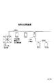
図4は、上記実施例に接続される自動試験機能付き火災感知器SA1を示すブロック図である。
【0023】
自動試験機能付き火災感知器SA1は、CPU41と、火災検出回路42と、自動試験回路43と、送受信回路44とを有する。自動試験機能付き火災感知器SA2等の他の自動試験機能付き火災感知器の構成も、自動試験機能付き火災感知器SA1と同様の構成を有する。
【0024】
CPU41は、自動試験機能付き火災感知器SA1の全体を制御するものであり、自動試験回路43は、火災検出回路42の機能が正常であるか否かを自動的に試験するものである。送受信回路44は、火災検出回路42が火災を検出したときに、独自のアドレスとともに火災信号をR型回線20Rに送出し、火災検出回路42が故障であることを示す故障信号が自動試験回路43によって出力されたときに、独自のアドレスとともに故障信号をR型回線20Rに送出するものである。
【0025】
次に、上記実施例の動作について説明する。
【0026】
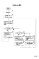
図5は、中継器CA1の動作を示すフローチャートである。
【0027】
まず、初期設定し(S1)、受信機10Pへの信号送出を停止し(S2)、火災感知器SA1、SA2、SA3、……の順で状態情報を収集し(S3)、このときに、火災感知器SA1、SA2、SA3、……のいずれから火災発報があれば(S4)、受信機10Pへ火災(発報)信号を送出する(S5)。つまり、スイッチング回路32をオンし、受信機側端子T1とT2との間のインピーダンス(P型回線20P間のインピーダンス)を抵抗R2の値に下げ、受信機側端子T1とT2との間の電圧を、火災発報に対応する電圧に変化させる。なお、受信機10P側で復旧操作が行われると、スイッチング回路32はオフとなる。
【0028】
一方、感知器SA1、SA2、SA3、……の順で状態情報を収集している(S3)ときに、故障信号を受信すれば(S11)、受信機10Pへ故障信号を送出する(S12)。つまり、スイッチング回路33をオンし、受信機側端子T1とT2との間のインピーダンス(P型回線20P間のインピーダンス)を抵抗R3の値に下げ、受信機側端子T1とT2との間の電圧を、故障信号に対応する電圧に変化させる。この場合、表示回路38によって故障が発生していることを表示する(S13)。
【0029】
感知器SA1、SA2、SA3、……の順で状態情報を収集している(S3)ときに、火災信号も故障信号も受信しなければ(S11)、特に信号は送出しないが、S12で故障信号を既に送出している場合には、受信機10Pへの故障信号送出を解除し(S14)、故障表示を解除する(S15)。
【0030】
このようにすれば、P型火災受信機10Pは、これに接続されている火災感知器から火災信号を受信することができ、また、自動試験機能付き火災感知器SA1、SA2、SA3、……からの故障信号を、中継器CA1を介して、受信することができる。この場合、火災報知設備における多数の火災感知器のうちの一部の火災感知器にのみ自動試験機能を付与してもP型火災受信機を使用することが出来るので、火災報知設備全体のコストを低く抑えることができ、さらに、必要な部分にのみ、自動試験機能付き火災感知器を配置することができる。
【0031】
なお、上記実施例における自動試験機能付き火災感知器の代わりに、ガスセンサ等の他の自動試験機能付きセンサを使用するようにしてもよい。
【0032】
また、火災感知器SA1等から送出された火災信号や故障信号を、中継器を介して火災受信機が受信した場合、火災の場合と故障の場合とでインピーダンスの値が異なるようにしているので、火災であるのか故障であるのかの判別をすることが可能である。火災感知器の故障が発生した場合、火災受信機のオペレータは、中継器が設置されている現場に出向き、そこで中継器の表示回路38をみることによって、より詳細な情報つまり、どの火災感知器が故障であるのかを把握することが可能となる。
【0033】
なお、本実施例では、火災感知器の場合にのみ中継器の表示回路に、その故障した火災感知器のアドレスを表示するようにしているが、火災の場合にも、火災発報した火災感知器のアドレスを表示できるように別の表示回路を設けるようにしてもよい。
【0034】
また、上記実施例では、火災用と故障用との2つのスイッチング回路を設けたが、これを1つにまとめてもよく、このようにすれば、既存の火災受信機に直ちに対応できる。
【0035】
【発明の効果】
本発明によれば、火災報知設備における多数の火災感知器のうちの一部の火災感知器にのみ自動試験機能を付与する場合、P型火災受信機を使用しても、火災感知、故障検出することができるという効果を奏する。
【図面の簡単な説明】
【図1】本発明の一実施例である火災報知設備における中継器CA1と、この周辺を示すブロック図である。
【図2】上記実施例である中継器CA1の一例を示すブロック図である。
【図3】中継器CA1の外観と、この中継器CA1に接続されるプリンタとを示す図である。
【図4】上記実施例に接続される自動試験機能付き火災感知器SA1を示すブロック図である。
【図5】中継器CA1の動作を示すフローチャートである。
【図6】従来の火災報知設備を示すブロック図である。
【符号の説明】
10P…P型火災受信機、
20P…P型回線、
20R…伝送の回線、
CA1…中継器、
SA1〜SA3…自動試験機能付き火災感知器、
SW1〜SE4、SE11〜SE13…一般型火災感知器、
31、41…CPU、
32、33…スイッチング回路、
37…送受信回路、
38…表示回路。[0001]
BACKGROUND OF THE INVENTION
The present invention relates to a repeater connected between a fire receiver and a fire detector.
[0002]
[Prior art]
In conventional fire alarm equipment, when performing an automatic test to determine whether the fire detector connected to the fire receiver is functioning normally, all of the connected fire detectors are subject to automatic testing. . That is, a fire detector having an automatic test function is connected to an R-type fire receiver via a transmission line, and a unique address different from each other is assigned to each of the fire detectors with the automatic test function. If any of the above fire detectors with automatic test function generates a failure signal, the R fire receiver individually identifies which of the fire detectors has failed. Can be identified.
[0003]
FIG. 6 is a block diagram showing a conventional fire alarm facility.
[0004]
In the above case, when the first transmission line 20R1 is connected to the R-
[0005]
[Problems to be solved by the invention]
By the way, in the surveillance area, there are areas where outside people do not like to enter more than necessary due to privacy (for example, the president's office), and areas where it is dangerous or difficult for people to enter, such areas are Since it is difficult to perform a test (inspection) even if a normal fire detector is installed, a fire detector with an automatic test function is often installed. Therefore, when the area requiring privacy protection is a part, it is sufficient to connect a fire detector with an automatic test function only to a part of the fire detector provided in the fire alarm facility. In this way, since an inexpensive general-purpose fire detector can be used in an area other than the area requiring privacy protection, the cost of the entire fire alarm system is reduced.
[0006]
However, if an address is assigned to one of the fire detectors connected to the fire receiver, and an attempt is made to communicate with that fire detector by polling, it is necessary to use an R-type fire receiver as the fire receiver. There is a problem that the cost of the fire receiver itself cannot be reduced. In other words, since the R-type fire receiver is expensive, even if the automatic test function is given only to some fire detectors, there is a problem that the fire alarm equipment is expensive as a whole. .
[0007]
The present invention can detect a fire and detect a failure even if a P-type fire receiver is used when an automatic test function is given to only some of the fire detectors in a fire alarm system. It aims at providing the repeater in the fire alarm equipment which can do.
[0008]
[Means for Solving the Problems]
The present invention includes a transmission / reception circuit that is connected to a plurality of fire detectors assigned different addresses and having an automatic test function via a transmission line and communicates with each of the fire detectors via the addresses, and the fire. Detection means for detecting a fire signal and a failure signal from a sensor, two receiver-side terminals connected to a P-type fire receiver via a P-type line, and when the detection means detects a fire signal The impedance value between the two receiver-side terminals is changed to the fire detection impedance value, while the impedance value between the two receiver-side terminals is failed when the detection means detects the failure signal. Impedance changing means that changes to an impedance value for detection, and when the detecting means detects the failure signal, at least one of the plurality of fire detectors has failed. A repeater and a failure display means for performing a fault indication indicating a.
[0009]
BEST MODE FOR CARRYING OUT THE INVENTION
FIG. 1 is a block diagram showing a repeater CA1 and its surroundings in a fire alarm facility that is an embodiment of the present invention.
[0010]
In this embodiment, two P-
[0011]
The repeater CA1 is connected to a plurality of fire detectors SA1 to SA3 having an automatic test function to which different addresses are assigned via the
[0012]
The fire detector SA1 with an automatic test function is assigned a unique address, can detect a failure by itself, and sends a fire signal and a failure signal to the repeater CA1. Fire detectors SA2, SA3,... With automatic test function are the same as fire detector SA1 with automatic test function.
[0013]
The automatic test includes the following two methods, and either method may be used in the present invention. The first method is to constantly monitor the analog amount of the signal sent from the fire detectors SA1 to SA3, and determine that a failure occurs when the analog amount deviates from a predetermined value. The second method is By turning on the test switch installed in the repeater, the fire detection circuit is simulated in the same state as at the time of the fire, and if a fire signal is sent at that time, the function of the fire detector is normal It is to be judged.
[0014]
FIG. 2 is a block diagram illustrating an example of the repeater CA1 according to the embodiment.
[0015]
The repeater CA1 includes a
[0016]
The
[0017]
The fire signal
[0018]
The transmission /
[0019]
The memory M stores the fact that the fire detector has output a failure signal, and stores the address and time of the fire detector that has output the failure signal. The contents stored in the memory M can be printed on the optional printer. The receiver side terminals T1 and T2 are terminals connected to the fire receiver P-
[0020]
FIG. 3 is a diagram showing the appearance of the repeater CA1 and the appearance of an optional printer connected to the repeater CA1.
[0021]
In FIG. 3, a switch SW is described as an example of the
[0022]
FIG. 4 is a block diagram showing a fire detector SA1 with an automatic test function connected to the above embodiment.
[0023]
The fire detector SA1 with an automatic test function includes a
[0024]
The
[0025]
Next, the operation of the above embodiment will be described.
[0026]
FIG. 5 is a flowchart showing the operation of the repeater CA1.
[0027]
First, initialization is performed (S1), signal transmission to the
[0028]
On the other hand, if status information is collected in the order of the sensors SA1, SA2, SA3,... (S3), if a failure signal is received (S11), the failure signal is sent to the
[0029]
When the state information is collected in the order of the sensors SA1, SA2, SA3,... (S3), if neither a fire signal nor a failure signal is received (S11), no signal is sent, but a failure occurs in S12. If the signal has already been transmitted, the failure signal transmission to the
[0030]
In this way, the P-
[0031]
In addition, you may make it use other sensors with automatic test functions, such as a gas sensor, instead of the fire detector with an automatic test function in the said Example.
[0032]
In addition, when the fire receiver or fire signal sent from the fire detector SA1 or the like is received by the fire receiver via the repeater, the impedance value is different between the fire and the failure. It is possible to determine whether it is a fire or a failure. In the event of a fire detector failure, the fire receiver operator goes to the site where the repeater is installed, where he looks at the
[0033]
In this embodiment, the address of the faulty fire detector is displayed on the display circuit of the repeater only in the case of a fire detector. Another display circuit may be provided so that the address of the device can be displayed.
[0034]
Further, in the above embodiment, two switching circuits for fire and for failure are provided, but these may be combined into one, and in this way, an existing fire receiver can be dealt with immediately.
[0035]
【The invention's effect】
According to the present invention, when an automatic test function is given only to some of the many fire detectors in the fire alarm facility, even if a P-type fire receiver is used, fire detection and failure detection are possible. There is an effect that can be done.
[Brief description of the drawings]
FIG. 1 is a block diagram showing a repeater CA1 and its surroundings in a fire alarm facility that is an embodiment of the present invention.
FIG. 2 is a block diagram showing an example of a repeater CA1 according to the embodiment.
FIG. 3 is a diagram illustrating an appearance of the repeater CA1 and a printer connected to the repeater CA1.
FIG. 4 is a block diagram showing a fire detector SA1 with an automatic test function connected to the embodiment.
FIG. 5 is a flowchart showing the operation of the repeater CA1.
FIG. 6 is a block diagram showing a conventional fire alarm facility.
[Explanation of symbols]
10P ... P type fire receiver,
20P ... P-type line,
20R ... Transmission line,
CA1 ... repeater,
SA1 to SA3 ... Fire detector with automatic test function,
SW1-SE4, SE11-SE13 ... General fire detectors,
31, 41 ... CPU,
32, 33 ... switching circuit,
37. Transmission / reception circuit,
38. Display circuit.
Claims (4)
上記火災感知器に、In the above fire detector,
火災検出回路の機能が正常であるか否かを自動的に試験し、故障信号を出力する自動試験回路を設け、An automatic test circuit that automatically tests whether the function of the fire detection circuit is normal and outputs a failure signal is provided.
上記中継器に、 In the above repeater,
故障であると判断された信号を、上記火災感知器から受信したか否かを検出する検出手段と;Detecting means for detecting whether or not a signal determined to be a failure has been received from the fire detector;
上記故障であると判断される信号を上記検出手段が検出したときに、上記2つの受信機側端子間のインピーダンス値を変化させるインピーダンス変換手段と; Impedance conversion means for changing an impedance value between the two receiver-side terminals when the detection means detects a signal determined to be the failure;
を設け、Provided,
上記P型回線に、上記中継器と一般型火災感知器とが接続されていることを特徴とする火災報知設備。A fire alarm system characterized in that the repeater and a general fire detector are connected to the P-type line.
上記火災感知器が故障信号を出力したことを記憶するメモリを、上記中継器に設け、上記故障信号を出力した火災感知器のアドレスと時刻とを、上記メモリに格納することを特徴とする火災報知設備。A fire for storing that the fire detector has output a failure signal is provided in the repeater, and the address and time of the fire detector that has output the failure signal are stored in the memory. Notification equipment.
上記中継器には、上記メモリに格納された内容を印字可能なプリンタが接続されていることを特徴とする火災報知設備。A fire alarm facility characterized in that a printer capable of printing the contents stored in the memory is connected to the repeater.
上記火災感知器の火災検出回路に、火災時と同じ状態を疑似的に作る試験スイッチが、上記中継器に設けられていることを特徴とする火災報知設備。A fire alarm system, characterized in that a test switch for making the same state as that at the time of a fire is provided in the fire detection circuit of the fire detector in the repeater.
Priority Applications (1)
| Application Number | Priority Date | Filing Date | Title |
|---|---|---|---|
| JP10443896A JP3710109B2 (en) | 1996-03-29 | 1996-03-29 | Repeater in fire alarm equipment |
Applications Claiming Priority (1)
| Application Number | Priority Date | Filing Date | Title |
|---|---|---|---|
| JP10443896A JP3710109B2 (en) | 1996-03-29 | 1996-03-29 | Repeater in fire alarm equipment |
Publications (2)
| Publication Number | Publication Date |
|---|---|
| JPH09270082A JPH09270082A (en) | 1997-10-14 |
| JP3710109B2 true JP3710109B2 (en) | 2005-10-26 |
Family
ID=14380676
Family Applications (1)
| Application Number | Title | Priority Date | Filing Date |
|---|---|---|---|
| JP10443896A Expired - Fee Related JP3710109B2 (en) | 1996-03-29 | 1996-03-29 | Repeater in fire alarm equipment |
Country Status (1)
| Country | Link |
|---|---|
| JP (1) | JP3710109B2 (en) |
Families Citing this family (2)
| Publication number | Priority date | Publication date | Assignee | Title |
|---|---|---|---|---|
| KR100750513B1 (en) * | 2006-06-08 | 2007-08-20 | 효림산업 주식회사 | P type and P type combined receiver for fire management |
| JP5709699B2 (en) * | 2011-09-06 | 2015-04-30 | 能美防災株式会社 | Fire alarm equipment and terminators used for it |
-
1996
- 1996-03-29 JP JP10443896A patent/JP3710109B2/en not_active Expired - Fee Related
Also Published As
| Publication number | Publication date |
|---|---|
| JPH09270082A (en) | 1997-10-14 |
Similar Documents
| Publication | Publication Date | Title |
|---|---|---|
| JP2886726B2 (en) | Disaster prevention system | |
| JP3710109B2 (en) | Repeater in fire alarm equipment | |
| JPH1196480A (en) | Automatic fire alarm | |
| JP2004133770A (en) | Fire alarm facility and fire sensor | |
| JP3073793B2 (en) | Fire alarm system | |
| JPH1196469A (en) | Automatic fire alarm | |
| JPH0652462A (en) | Disaster preventing facility | |
| JP3287925B2 (en) | Fire detector with repeater function | |
| JP3678599B2 (en) | Test system and test method | |
| JP2994105B2 (en) | Test equipment for disconnection detection function in fire alarm equipment | |
| JP3750886B2 (en) | Method and apparatus for controlling fire indicator | |
| JP2000076565A (en) | Fire alarm | |
| JP2558870B2 (en) | Fire alarm | |
| JP2000187784A (en) | Fire sensor, fire warning receiver, fire warning reception system using them | |
| JP3284324B2 (en) | Fire detector | |
| JP3168349B2 (en) | Sensor connection test method and device | |
| JPH0765262A (en) | Fire detection system and fire sensor | |
| JPH09212765A (en) | Automatic fire alarm receiver | |
| JP3379844B2 (en) | Fire alarm system | |
| JPH07254095A (en) | Disaster prevention monitoring system | |
| JP3168222B2 (en) | Fire alarm system | |
| JP2007323197A (en) | Fire alarm equipment | |
| JPH09163465A (en) | Remote supervisory system | |
| JPH0565918B2 (en) | ||
| JPH05334580A (en) | Fire alarming facility |
Legal Events
| Date | Code | Title | Description |
|---|---|---|---|
| A977 | Report on retrieval |
Free format text: JAPANESE INTERMEDIATE CODE: A971007 Effective date: 20040316 |
|
| A131 | Notification of reasons for refusal |
Free format text: JAPANESE INTERMEDIATE CODE: A131 Effective date: 20040827 |
|
| A521 | Written amendment |
Free format text: JAPANESE INTERMEDIATE CODE: A523 Effective date: 20041026 |
|
| TRDD | Decision of grant or rejection written | ||
| A01 | Written decision to grant a patent or to grant a registration (utility model) |
Free format text: JAPANESE INTERMEDIATE CODE: A01 Effective date: 20050805 |
|
| A61 | First payment of annual fees (during grant procedure) |
Free format text: JAPANESE INTERMEDIATE CODE: A61 Effective date: 20050808 |
|
| R150 | Certificate of patent or registration of utility model |
Free format text: JAPANESE INTERMEDIATE CODE: R150 |
|
| LAPS | Cancellation because of no payment of annual fees |