JP3710147B2 - Terminal structure - Google Patents
Terminal structure Download PDFInfo
- Publication number
- JP3710147B2 JP3710147B2 JP06432794A JP6432794A JP3710147B2 JP 3710147 B2 JP3710147 B2 JP 3710147B2 JP 06432794 A JP06432794 A JP 06432794A JP 6432794 A JP6432794 A JP 6432794A JP 3710147 B2 JP3710147 B2 JP 3710147B2
- Authority
- JP
- Japan
- Prior art keywords
- pressing
- terminal
- electric wire
- hollow cylindrical
- cylindrical case
- Prior art date
- Legal status (The legal status is an assumption and is not a legal conclusion. Google has not performed a legal analysis and makes no representation as to the accuracy of the status listed.)
- Expired - Fee Related
Links
Images
Landscapes
- Breakers (AREA)
Description
【0001】
【産業上の利用分野】
本発明は端子の接続部の構造に関し、詳しくは電線接続の長期安定的な信頼性を高めるとともに、簡単且つ迅速に接続作業が出来る端子部に関する。
【0002】
【従来の技術】
従来この種の端子部における構造は、圧着端子、電線をネジで直接締め付けるもの、パイプ端子にネジを設けて電線を直接締め付けるもの、電線上部を蓋う部材等と共にネジで締め付けるもの等がある。
【0003】
【発明が解決しようとする課題】
従来の圧着端子は、作業現場に圧着器具を持込み操作することが難儀であるため正確に圧着できない場合があり、ネジで電線を直接締め付けるもの又は蓋う部材と共にネジで締め付けるもの等は、使用後一定期間経過するとネジが物理的に必ず緩み締め直さなければ接続不良を生じる恐れがあり信頼が持てなかった。
【0004】
そこで、電線の締め付け作業が簡単且つ締め付け度合いに多少の強弱があっても確実に電線が接続され、更に、押ネジに緩みが生じても電線押圧力が緩まず恒久的に安定した導電が得られ信頼性の高い端子の開発が切望されていた。
【0005】
【課題を解決するための手段】
本願発明の端子部の構造は、中空筒状のケースと、
挿入される電線の外形に対応させて電線が少し余裕をもって挿入できる程度の大きさの内径に形成した円形孔を備える筒状の筒端子であって、周壁には外部から押圧バネの一部を円形孔内に挿入された電線に向けて差し込む為の切開部が形成してある筒端子と、
断面をW字状に形成してそれの両端をケースに装着する為の支持部とし、W字状の中央部に位置する凸部を押ネジに対接させる加圧部とし、かつW字状の中央部に位置する加圧部の両側における二つの凹状部を電線を押さえ付ける為の押圧部としている押圧バネと、
中空筒状のケースの周壁に対して回動自在に装着して押圧バネにおけるW字状の中央部に位置する加圧部を押圧する為の押ネジとを備え、
上記中空筒状ケース内には、上記筒端子を、切開部が中空筒状ケース内壁と空間を隔てた状態で押ネジの存在する方向に向き、かつ、筒端子の軸心が中空筒状ケースの軸芯と平行する状態で中空筒状ケース内壁に接して存置させ、
上記押圧バネは、中空筒状ケース内における中空筒状ケース内壁と上記筒端子との間隙に、二つの支持部と二つの押圧部と加圧部とが筒端子の軸心方向に並び、二つの支持部の一方は上記中空筒状ケースの電線挿入側に、他方は奥部側に夫々取り付けられ、二つの押圧部は夫々挿入される電線の前後の外周を切開部を通しての押し圧を可能に位置させ、
加圧部は、中空筒状ケースの周壁に対して回動自在に装着してある押ネジによっての押圧を可能に押ネジの先端に対向させた位置になるよう配設し、
中空筒状ケースの周壁に対して回動自在に装着してある押ネジの回動によって、上記二つの押圧部が、上記筒端子に挿入される電線の前後の外周を押し圧し、電線の外周面を、電線が少し余裕をもって挿入できる程度の大きさに形成してある内径の上記筒端子における円形孔内壁の円弧面に当接させることができるようにしてある。
【0006】
押圧バネの前後端をケースで支え、前後端との間の複数の押圧部が筒端子の切開部の口開部から押し圧可能にし、電線を挿入後、押ネジ等を締め付けると押圧部に電線が押圧され筒端子の円形孔の壁面に支えられて崩れず接続を保つ。
【0007】
特に図示されている撚線を接続する場合においては、筒端子を用い押圧部が位置する部分に複数の切開部を設け、電線を挿入後押ネジ等を締め付けると押圧部が直接電線を押圧し、より線は円形孔の内壁に支えられ全体が緩むことなく接続が安定する。
【0008】
更に、筒端子の円形孔の奥部をテーパーに形成し、そのテーパー孔部分に挿入した撚り線端末は、全体が円形孔の内壁に押し付けられ、特に撚線の崩れを防止する。
【0009】
本願発明は、より線に限らず単線に用いても何ら支障無く使用でき、電線が固定するなどの効果が得られる。
【0010】
【作用】
押ネジ等を締め付けると押圧部が電線と端子を締め付け、一定期間使用後の押ネジ等及び電線の緩みを押圧バネの弾力性の蓄積で補強し、堅固な押ネジ等が押圧バネの緩みを補強する。
【0011】
切開部を設けた筒端子を用いると、電線がその内壁全体に支えられるとともに、押圧部が直接電線を押圧できる。
【0012】
奥部に向けて緩やかに細くテーパー孔を形成した筒端子を使用すると、電線の外径に差があってもテーパー部分で自動的に合致する位置が定まり、挿入した電線端末がテーパー内壁に押し付けられ、電線全体の緩み崩れを防止する。
【0013】
【実施例】
以下本願の実施例を示す図面について説明すると、1は筒端子であり、電線7を挿入し支える円形孔2を形成しその奥部はテーパー孔3を形成し電線7の端末が押し付けられ、円形孔2と共に電線7全体を崩さず原形を保つ。
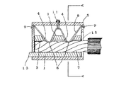
円形孔2の内径は、図1及び図3に示されるように、電線7が少し余裕をもって挿入できる程度に電線7の外径に対応する大きさに形成し、押圧部6、6で挿入された電線7を押圧した状態では図3に示されるように、電線7の両側が円形孔2の内壁に当接するような内径に形成してある。円形孔2は口開部12から奥底の少し前まで平行孔に形成してある。また円形孔2の内径は全長を緩やかなテーパー孔にしてもよい。テーパー孔3は図5に示すように奥部の一部に限りテーパーにし、電線7の外径に差があつても挿入時にテーパー孔3の部分で調節され端末部分がその内壁全周に押し付けられ固定するため安定的に接続を保つ。4・4は切開部であり、筒端子1の上部に複数設け押圧部6・6が触れることなく入る大きさに口開しておく。5はケースであり、一方に口開部を形成し、前後の側部に細長い横孔を設けている。この横孔には、図1に示されているように断面をW字状に形成してある押圧バネ8の両端の支持部9・9を取付ける。押圧部6・6は押圧バネ8の両端中間に複数設け、図1に表れているように切開部4・4の位置にある電線7の上部に定着させる。断面がW字状の押圧バネ8における中央部に位置する凸部の加圧部に図示のように押ネジ11を対接させ、押ネジ11をネジ込むと断面がW字状の押圧バネ8における凸部の加圧部の両側に位置する凹状の押圧部6、6は図1、図3に現れているように電線7を直接押圧する。電線7はより線に限らず単線でも使用できる。押圧バネ8は押ネジ11で強固に押圧定着すると共に弾力性を蓄積し、押ネジ11の物理的緩み及び電線7の通電による緩みを補強する。10はバネ先端であり、ケース5の前部に設けた押圧ネジ11で締め付けると押圧部6・6が作動し電線7を同時に押圧する。押ネジ11は押圧バネ8を強固に押圧し定着させる。口開部12は筒端子1に電線7の先端が容易に入るよう少し余裕のある内径にする。13は連結部であり、それぞれの端子が電線7から導電した電気を次ぎに送電する接続部である。14は滑り止めであり、円形孔2に線を多数形成し電線7の滑り止めを成す。
【0014】
図1においては、押圧バネ8を用いて筒端子1内の電線7の接続状態を示す一部の側断面図であり、図5に示す筒端子1をケース5に装着し、その奥まで電線7を差し込み奥のテーパー孔3に端末を押し付け固定し、ケース5の前後に設けた横孔に押圧バネ8の両端を取付けて支え、V字形の押圧部6・6が筒端子1の上部に設けた切開部4・4の入口に位置させ、押圧バネ8の中央上部に押ネジ11をケース5に取付けておき、これをネジ込むと押圧バネ8が下降し押圧部6・6が電線7を均一的に押圧し筒端子1に接続する。押し圧される電線7は円形孔2の全壁及びテーパー孔3に支えられ縒りが崩れず接続が安定する。接続後一定期間を経過すると物理的に押ネジ11は緩みを生ずるが、押圧バネ8が蓄積している弾力性が作用し、その緩みを補強し電線7に対する押圧力が弱小すること無く、従って一定期間使用後の点検及び押ネジ11の締め直し無用となり手間が省けるばかりか、締め直しを怠った場合の危険性が解消する。
【0015】
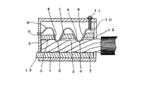
図2においては、図1と同じく筒端子の一部側断面図であり、図1とは異なり、底部に向けて細く緩やかなテーパー形状の円形孔2を形成した筒端子1の実施例を示すものである。ケース5に装着した筒端子1は、例えば後部に押圧バネ8の後端9を取り付けて支え、押圧バネ8の先端上部に押ネジ11を取付け、切開部4・4の入口に押圧部6・6を位置させておき、電線7を口開部12から差し込むと奥のテーパー孔3に先端が挿入して図示のように内壁に囲まれ、それにより強く締め付けられ、次ぎに押ネジ11をネジ込むとバネ先端10が押し圧され押圧部6・6が電線7を押圧し円形孔2の壁面により線部分が支えられて崩れず押圧力が安定する。押圧部6・6においては弾力性を有しており、使用後一定期間が経過した押ネジ11及び電線7の緩みを補強するに足る剛性な弾力性が作用し電線7に対する押圧力が緩むことなく安定した導電効果を保ち、押ネジ11の締め直し無用であり保安上点検の手間が省けるなど信頼性が著しく向上する。
【0016】
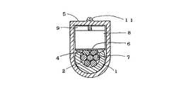
図3においては、図1のA−A断面図であり、押ネジ11で押圧バネ8の中央部頂点を経て押圧部6・6に圧縮された電線7が筒端子1の円形孔2の壁面に支えらて崩れず固定した完全な接続導電状態を示している。
【0017】
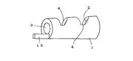
図4においては、筒端子1の斜視図であり、テーパー孔3、切開部4・4の状態を示しており、外形は円形に限らず、必要に応じ任意の形状でよく、漏電遮断器の構造等の条件に適した形状にすれば効果的である。
【0018】
図5においては、筒端子1の側断面図であり、テーパー孔3の内壁状態と、平行な円形孔2及び切開部4・4の溝の深さを示している。更に、筒端子1の円形孔2の形状は、口開部12から奥底部に至る全長を同径による平行孔であっても、切開部4・4を設けて押圧部6・6を形成する押圧バネ8との組み合わせ構造にすれば、本願の効果は充分得られる。更に、円形孔2の下部壁面に滑り止め14の線を多数を並列に設けておけば電線7の抜け止めとなる。
【0019】
作業条件の悪い場所で使用する場合においても、本願による漏電遮断器の各端子部は、押ネジ11で剛性な押圧バネ8を押し圧しても弾力性が作用して非常に軽く締まり、しかも1本の押ネジ11をネジ込むだけで複数の押圧部を一挙に押圧作動し、作業が簡単容易であり省力化の効果も得られる。
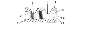
【0020】
なお、本願の押圧バネ8を用いる端子部については、本願の筒端子1の使用に限定されること無く、従来使用されている総ての端子部に応用可能であり、その場合においても何ら劣ることなく本願による効果が得られる特徴をも兼ね備えている。
【0021】
【発明の効果】
以上のように本願発明にあっては、押圧バネ8の特徴である弾力性と、押ネジ11の持つ堅固性とを組み合わせた構造にしたことにより、押圧バネ8だけでは緩みを生ずる欠点を押ネジの持つ強固性で補強し、押ネジ11が物理的に緩む欠点及び通電による電線の緩みを押圧バネ8の持つ弾力性の蓄積分で補強する構造にしたことにより強力且つ剛性な押圧力を均一的に持続し、長期に安定した接続導電による信頼性を飛躍的に向上させた。
【0022】
筒端子1の円形孔2及びテーパー孔3に電線7を挿入して支え、切開部4から押圧部6、6が直接電線7を押圧するようにして安定した接続を可能にした。
特に、筒状の筒端子1は、挿入される電線7の外形に対応させて電線が少し余裕をもって挿入できる程度の大きさの内径に形成した円形孔を備えるので、押圧部6,6で押圧した状態では、図3に現れるように電線の両側は円形孔の内壁における円弧面で囲んで、そこの型崩れを保護する特長がある。
【0023】
押ネジ11をネジ込む場合、押圧バネ8の弾力性が働き軽く締まり、更に1本の押圧バネ11を締めれば複数の押圧部6、6が押圧作用するなど、作業条件の悪い場所においても簡単正確な接続作業が容易にできる特長をも有する。
繰り返すと、押圧バネ8は、二つの支持部9,9の一方は上記中空筒状ケース5の電線挿入側に、他方は奥部側に夫々取り付け、二つの押圧部6,6は夫々挿入される電線7の前後の外周を切開部4,4を通しての押し圧を可能に位置させ、加圧部は、中空筒状ケースの周壁に対して回動自在に装着してある押ネジ11によっての押圧を可能に押ネジの先端に対向させた位置になるよう配設するものであるから、前述したように1本の押圧バネ11を締めれば複数の押圧部6・6が同時に押圧でき、電線7を複数カ所で、堅固に、しかも迅速に締め付けできる効果がある。
【0024】
【図面の簡単な説明】
【図1】 支持部9で両端を支え、押圧バネ8の中央部を押ネジ11で押圧し、電線7が筒端子1に押し付けた状態を示す一部側断面図。
【図2】 底部に向けて細く緩やかなテーパー形状の円形孔2を形成した例を示し、電線7を挿入した状態を示す一部側断面図。
【図3】 切開部4・4から押圧部6・6で電線7を押圧した状態を示すA−A断面図。
【図4】 筒端子1の斜視図。
【図5】 筒端子1の側断面図。
【符号の説明】
1 筒端子
2 円形孔
3 テーパー孔
4 切開部
5 ケース
6 押圧部
7 電線
8 押圧バネ
9 支持部
10 バネ先端
11 押ネジ
12 口開部
13 連結部
14 滑り止め[0001]
[Industrial application fields]
The present invention relates to a structure of a terminal connecting portion, and more particularly to a terminal portion that can improve the long-term stable reliability of electric wire connection and can be easily and quickly connected.
[0002]
[Prior art]
Conventionally, this type of terminal portion includes a crimp terminal, a wire that is directly tightened with a screw, a screw that is provided on a pipe terminal to directly tighten the wire, and a screw that is tightened together with a member that covers the upper portion of the wire.
[0003]
[Problems to be solved by the invention]
Conventional crimp terminals cannot be accurately crimped because it is difficult to bring a crimping instrument into the work site, and it may not be possible to crimp accurately. When a certain period of time has passed, the screws may not be physically loosened and tightened, resulting in poor connection and unreliability.
[0004]
Therefore, even if the tightening operation of the wire is simple and the tightening degree is somewhat strong, the wire is securely connected, and even if the push screw is loosened, the wire pressing force does not loosen and a permanent and stable conductivity is obtained. The development of highly reliable terminals was eagerly desired.
[0005]
[Means for Solving the Problems]
The structure of the terminal portion of the present invention is a hollow cylindrical case,
A cylindrical tube terminal having a circular hole formed in the inner diameter of a size that allows the wire to be inserted with a slight margin corresponding to the outer shape of the inserted wire, and a part of the pressing spring is externally attached to the peripheral wall A tube terminal in which an incision is formed for insertion toward the electric wire inserted into the circular hole;
The cross section is formed in a W shape and both ends thereof are used as support parts for mounting on the case, and the convex part located at the center part of the W shape is used as a pressurizing part that comes into contact with the push screw. A pressing spring as a pressing part for pressing the electric wire with two concave parts on both sides of the pressing part located in the center of
A pressing screw for rotatably mounting on the peripheral wall of the hollow cylindrical case and pressing the pressing portion located at the W-shaped central portion of the pressing spring;
In the hollow cylindrical case, the cylindrical terminal is oriented in the direction in which the push screw is present with the incision portion separating the space from the inner wall of the hollow cylindrical case, and the axial center of the cylindrical terminal is the hollow cylindrical case In contact with the inner wall of the hollow cylindrical case in a state parallel to the axis of the
The pressing spring includes two support portions, two pressing portions, and a pressing portion arranged in the axial direction of the cylindrical terminal in a gap between the inner wall of the hollow cylindrical case and the cylindrical terminal in the hollow cylindrical case. One of the two support parts is attached to the wire insertion side of the hollow cylindrical case, and the other is attached to the back side. The two pressing parts can push the outer circumference of the inserted wire through the incision part. Located in
The pressurizing part is disposed so as to be opposed to the tip of the push screw so as to be able to be pressed by a push screw that is rotatably attached to the peripheral wall of the hollow cylindrical case,
The two pressing portions press and compress the outer circumference of the electric wire inserted into the cylindrical terminal by the rotation of the push screw rotatably attached to the peripheral wall of the hollow cylindrical case, and the outer circumference of the electric wire The surface can be brought into contact with the circular arc surface of the inner wall of the circular hole in the cylindrical terminal having an inner diameter formed so as to allow the electric wire to be inserted with a slight margin.
[0006]
The front and rear ends of the pressing spring are supported by the case, and a plurality of pressing portions between the front and rear ends can be pressed from the opening of the incision portion of the tube terminal. The wire is pressed and supported by the wall surface of the circular hole of the tube terminal, and the connection is maintained without breaking.
[0007]
In particular, when connecting the stranded wires shown in the figure, use a tube terminal to provide a plurality of incisions in the part where the pressing part is located, and after inserting the electric wire, tighten the push screw and the pressing part directly presses the electric wire. The stranded wire is supported by the inner wall of the circular hole and the connection is stabilized without loosening the whole.
[0008]
Further, the inner end of the circular hole of the cylindrical terminal is formed into a taper, and the entire stranded wire terminal inserted into the tapered hole portion is pressed against the inner wall of the circular hole, and particularly prevents the twisted wire from collapsing.
[0009]
The present invention can be used without any problem even if it is used not only for a stranded wire but also for a single wire, and an effect such as fixing an electric wire can be obtained.
[0010]
[Action]
When the push screw is tightened, the pressing part tightens the electric wire and terminal, and the looseness of the push screw and the electric wire after a certain period of use is reinforced by the accumulation of elasticity of the press spring. Reinforce.
[0011]
When the cylindrical terminal provided with the incision portion is used, the electric wire is supported on the entire inner wall, and the pressing portion can directly press the electric wire.
[0012]
When using a cylindrical terminal with a tapered hole that is gently narrowed toward the back, even if there is a difference in the outer diameter of the wire, the position where it automatically matches is determined at the tapered portion, and the inserted wire end is pressed against the tapered inner wall This prevents the entire wire from coming loose.
[0013]
【Example】
Referring to the drawings showing the embodiments of the present application, 1 is a cylindrical terminal, which forms a
As shown in FIGS. 1 and 3, the inner diameter of the
[0014]
In FIG. 1, it is a partial sectional side view which shows the connection state of the
[0015]
2 is a partial cross-sectional side view of the tube terminal as in FIG. 1. Unlike FIG. 1, an embodiment of the
[0016]
3 is a cross-sectional view taken along the line AA in FIG. 1, and the
[0017]
FIG. 4 is a perspective view of the
[0018]
In FIG. 5, it is a sectional side view of the
[0019]
Even when used in a place with poor working conditions, each terminal portion of the earth leakage breaker according to the present invention is very lightly tightened even if the rigid
[0020]
In addition, about the terminal part using the
[0021]
【The invention's effect】
As described above, according to the present invention, the structure that combines the elasticity characteristic of the
[0022]
An
In particular, the
[0023]
When the pressing screw 11 is screwed in, the elasticity of the
If it repeats, as for the
[0024]
[Brief description of the drawings]
FIG. 1 is a partial side cross-sectional view showing a state in which both ends are supported by a
FIG. 2 is a partial side cross-sectional view illustrating an example in which a
FIG. 3 is a cross-sectional view taken along line AA showing a state where the
4 is a perspective view of a
FIG. 5 is a side sectional view of a
[Explanation of symbols]
DESCRIPTION OF
Claims (2)
挿入される電線の外形に対応させて電線が少し余裕をもって挿入できる程度の大きさの内径に形成した円形孔を備える筒状の筒端子であって、周壁には外部から押圧バネの一部を円形孔内に挿入された電線に向けて差し込む為の切開部が形成してある筒端子と、
断面をW字状に形成してそれの両端をケースに装着する為の支持部とし、W字状の中央部に位置する凸部を押ネジに対接させる加圧部とし、かつW字状の中央部に位置する加圧部の両側における二つの凹状部を電線を押さえ付ける為の押圧部としている押圧バネと、
中空筒状のケースの周壁に対して回動自在に装着して押圧バネにおけるW字状の中央部に位置する加圧部を押圧する為の押ネジとを備え、
上記中空筒状ケース内には、上記筒端子を、切開部が中空筒状ケース内壁と空間を隔てた状態で押ネジの存在する方向に向き、かつ、筒端子の軸心が中空筒状ケースの軸芯と平行する状態で中空筒状ケース内壁に接して存置させ、
上記押圧バネは、中空筒状ケース内における中空筒状ケース内壁と上記筒端子との間隙に、二つの支持部と二つの押圧部と加圧部とが筒端子の軸心方向に並び、二つの支持部の一方は上記中空筒状ケースの電線挿入側に、他方は奥部側に夫々取り付けられ、二つの押圧部は夫々挿入される電線の前後の外周を切開部を通しての押圧を可能に位置させ、
加圧部は、中空筒状ケースの周壁に対して回動自在に装着してある押ネジによっての押圧を可能に押ネジの先端に対向させた位置になるよう配設し、
中空筒状ケースの周壁に対して回動自在に装着してある押ネジの回動によって、上記二つの押圧部が、上記筒端子に挿入される電線の前後二カ所の外周を押圧し、電線の外周面を、電線が少し余裕をもって挿入できる程度の大きさに形成してある内径の上記筒端子における円形孔内壁の円弧面に当接させることができるようにしてあることを特徴とする端子部の構造。A hollow cylindrical case,
A cylindrical tube terminal having a circular hole formed in the inner diameter of a size that allows the wire to be inserted with a slight margin corresponding to the outer shape of the inserted wire, and a part of the pressing spring is externally attached to the peripheral wall A tube terminal in which an incision is formed for insertion toward the electric wire inserted into the circular hole;
The cross section is formed in a W shape and both ends thereof are used as support parts for mounting on the case, and the convex part located at the center part of the W shape is used as a pressurizing part that comes into contact with the push screw. A pressing spring as a pressing part for pressing the electric wire with two concave parts on both sides of the pressing part located in the center of
A pressing screw for rotatably mounting on the peripheral wall of the hollow cylindrical case and pressing the pressing portion located at the W-shaped central portion of the pressing spring;
In the hollow cylindrical case, the cylindrical terminal is oriented in the direction in which the push screw is present with the incision portion separating the space from the inner wall of the hollow cylindrical case, and the axial center of the cylindrical terminal is the hollow cylindrical case In contact with the inner wall of the hollow cylindrical case in a state parallel to the axis of the
The pressing spring includes two support portions, two pressing portions, and a pressing portion arranged in the axial direction of the cylindrical terminal in a gap between the inner wall of the hollow cylindrical case and the cylindrical terminal in the hollow cylindrical case. One of the two support parts is attached to the wire insertion side of the hollow cylindrical case, and the other is attached to the back side, and the two pressing parts allow the front and rear outer circumferences of the inserted wires to be pressed through the incision part, respectively. Position
The pressurizing part is disposed so as to be opposed to the tip of the push screw so as to be able to be pressed by a push screw that is rotatably attached to the peripheral wall of the hollow cylindrical case,
The two pressing portions press the outer circumferences of the two front and rear portions of the electric wire inserted into the cylindrical terminal by the rotation of the push screw that is rotatably attached to the peripheral wall of the hollow cylindrical case, and the electric wire A terminal characterized in that the outer peripheral surface can be brought into contact with the circular arc surface of the inner wall of the circular hole in the cylindrical terminal having an inner diameter formed so that the electric wire can be inserted with a slight margin. Part structure.
Priority Applications (1)
| Application Number | Priority Date | Filing Date | Title |
|---|---|---|---|
| JP06432794A JP3710147B2 (en) | 1994-02-22 | 1994-02-22 | Terminal structure |
Applications Claiming Priority (1)
| Application Number | Priority Date | Filing Date | Title |
|---|---|---|---|
| JP06432794A JP3710147B2 (en) | 1994-02-22 | 1994-02-22 | Terminal structure |
Publications (2)
| Publication Number | Publication Date |
|---|---|
| JPH07235253A JPH07235253A (en) | 1995-09-05 |
| JP3710147B2 true JP3710147B2 (en) | 2005-10-26 |
Family
ID=13255039
Family Applications (1)
| Application Number | Title | Priority Date | Filing Date |
|---|---|---|---|
| JP06432794A Expired - Fee Related JP3710147B2 (en) | 1994-02-22 | 1994-02-22 | Terminal structure |
Country Status (1)
| Country | Link |
|---|---|
| JP (1) | JP3710147B2 (en) |
Families Citing this family (2)
| Publication number | Priority date | Publication date | Assignee | Title |
|---|---|---|---|---|
| KR100458333B1 (en) * | 2001-12-24 | 2004-11-26 | 형제전기주식회사 | Circuit breaker of jointing combinative terminal |
| CN116073296B (en) * | 2022-11-30 | 2026-05-26 | 淮南师范学院 | A data storage device cable assembly |
-
1994
- 1994-02-22 JP JP06432794A patent/JP3710147B2/en not_active Expired - Fee Related
Also Published As
| Publication number | Publication date |
|---|---|
| JPH07235253A (en) | 1995-09-05 |
Similar Documents
| Publication | Publication Date | Title |
|---|---|---|
| FR2586143A1 (en) | SELF-LOCKING ELECTRICAL CONNECTOR | |
| JPS6321317B2 (en) | ||
| EP0825681B1 (en) | Battery terminal | |
| JPH11273764A (en) | Contact member with screw connection | |
| US5573433A (en) | Electric wire connector | |
| US4781617A (en) | Cable connector arrangement to accommodate multiple cable sizes | |
| JP2612553B2 (en) | Wire end treatment cap | |
| US4830624A (en) | Twist-on battery connector | |
| JP3086755U (en) | Battery connector structure | |
| US20020002009A1 (en) | Insulation-displacement connection piece | |
| JP3574916B2 (en) | Battery adapter | |
| US7033231B2 (en) | Radial screw connecting device for an electrical wire | |
| CN211017430U (en) | Power grid primary equipment wire clamp | |
| JPH07235253A (en) | Terminal part of earth leakage breaker | |
| JP2002165323A (en) | Power cable conductor connection parts | |
| JPH0770336B2 (en) | Cord removal prevention device in connector | |
| US20250125567A1 (en) | Wireless signal extender | |
| JP3733474B2 (en) | Waterproof flexible conduit connector | |
| KR200154114Y1 (en) | Pipe jointing structure | |
| KR940004442Y1 (en) | Pipe connector | |
| KR200149900Y1 (en) | Combination structure of antenna plug and jack | |
| KR840001048Y1 (en) | Tension Clamp for Aluminum Wiring | |
| JP3288636B2 (en) | Coaxial cable plug | |
| KR860002356Y1 (en) | Pulling eye | |
| JPS6348951Y2 (en) |
Legal Events
| Date | Code | Title | Description |
|---|---|---|---|
| A977 | Report on retrieval |
Free format text: JAPANESE INTERMEDIATE CODE: A971007 Effective date: 20040917 |
|
| A131 | Notification of reasons for refusal |
Free format text: JAPANESE INTERMEDIATE CODE: A131 Effective date: 20040928 |
|
| A602 | Written permission of extension of time |
Free format text: JAPANESE INTERMEDIATE CODE: A602 Effective date: 20041221 |
|
| A521 | Written amendment |
Free format text: JAPANESE INTERMEDIATE CODE: A523 Effective date: 20041228 |
|
| A131 | Notification of reasons for refusal |
Free format text: JAPANESE INTERMEDIATE CODE: A131 Effective date: 20050621 |
|
| A521 | Written amendment |
Free format text: JAPANESE INTERMEDIATE CODE: A523 Effective date: 20050623 |
|
| TRDD | Decision of grant or rejection written | ||
| A01 | Written decision to grant a patent or to grant a registration (utility model) |
Free format text: JAPANESE INTERMEDIATE CODE: A01 Effective date: 20050726 |
|
| A61 | First payment of annual fees (during grant procedure) |
Free format text: JAPANESE INTERMEDIATE CODE: A61 Effective date: 20050809 |
|
| R150 | Certificate of patent or registration of utility model |
Free format text: JAPANESE INTERMEDIATE CODE: R150 |
|
| LAPS | Cancellation because of no payment of annual fees |