【0001】
【発明の属する技術分野】
本発明は、浴槽水のpHを調整する浴槽水の水質改変装置に関するものである。
【0002】
【従来の技術】
浴槽内の温水を電気分解して循環させ、酸性イオン水の有する温水を殺菌する効果やアストリンゼン効果、あるいはアルカリ性イオン水が有するトリートメント効果を享受するための装置は、従来種々のものが提案されており、例えば特開平4−312461号公報に開示されているものがある。この公報に開示されている装置においては、浴槽の温水を加熱保温する保温手段と、水を電気分解して酸性イオン水とアルカリ性イオン水とを生成する電気分解手段とを備えており、酸性イオン水とアルカリ性イオン水とを適宜浴槽内に還流できるようにしていた。
【0003】
【発明が解決しようとする課題】
しかしこのような従来技術においては、下記のような問題があった。
(1) 電気伝導度の低い浴槽水を電気分解しているため、電気分解に必要な電流を流すためには電極間に高い電圧を印可しなければならず、電力コストが高いものであった。
(2) 浴槽に送り込まれないイオン水は、浴槽外に連続的に排出されるため、排水量が多くなり、浴槽水の減少が激しいものであった。
(3) アルカリ性イオン水を浴槽に供給している間は、アルカリ性イオン水には塩素が含まれないため、浴槽の湯を殺菌することができず、衛生上問題があった。
(4) 酸性イオン水を排水する場合、この酸性イオン水中の有害で有臭の塩素ガスが気化し、雰囲気中に放出されるという問題があった。
【0004】
本発明は上記の点に鑑みてなされたものであり、上記課題を解決することができる浴槽水の水質改変装置を提供することを目的とするものである。
【0005】
【課題を解決するための手段】
本発明の請求項1に係る浴槽水の水質改変装置は、有隔膜電解槽2と、有隔膜電解槽2内の隔膜45にて隔てられた第一電極室2aと第二電極室2bのうちの第二電極室2b内に塩化ナトリウムを供給する塩水供給槽4と、電気分解に供される浴槽水31を浴槽1から有隔膜電解槽2に供給し、有隔膜電解槽2にて電気分解により生成するアルカリ性イオン水と酸性イオン水のうち一方のイオン水を第一電極室2aから浴槽1に供給すると共に他方のイオン水を第二電極室2bから浴槽1外に排出する浴槽水の流路と、この浴槽水の流路に水流を発生させる循環ポンプ5とを具備し、循環ポンプ5は電解導入路12、電解槽路30を経由し、第一電極室路14及び第二電極室路15に分岐して第一電極室2aと第二電極室2bにそれぞれ接続され、塩水供給槽4は電解導入路12から分岐した塩水槽路13に接続され更に塩供給路17を経て第二電極室路15に接続されていることを特徴とするものである。
【0006】
また本発明の請求項2に係る浴槽水の水質改変装置は、請求項1の構成に加えて、開閉弁を開閉することにより有隔膜電解槽2における電気分解の進行中に、有隔膜電解槽2にて電気分解により生成するアルカリ性イオン水と酸性イオン水のうち一方のイオン水を第一電極室2aから連続的に浴槽1に供給し、有隔膜電解槽2における電気分解の終了後に他方のイオン水を第二電極室2bから浴槽1外に排出する浴槽水の流路を具備し、前記開閉弁として、塩水槽路13の流通を開閉する開閉弁と、第二電極室路15における塩供給路17の接続位置よりも上流側の流通を開閉する開閉弁と、イオン水を第二電極室2bから浴槽1外に排出する流路を開閉する開閉弁とを備えることを特徴とするものである。
【0007】
また本発明の請求項3に係る浴槽水の水質改変装置は、有隔膜電解槽2と、有隔膜電解槽2内の隔膜45にて隔てられた第一電極室2aと第二電極室2bの両方の電極室内に塩化ナトリウムを供給する塩水供給槽4と、開閉弁を開閉することにより電気分解に供される浴槽水31を浴槽1から有隔膜電解槽2に供給し、有隔膜電解槽2における電気分解終了後に、有隔膜電解槽2にて電気分解により生成するアルカリ性イオン水と酸性イオン水のうちの一方のイオン水を第一電極室2aから浴槽1に供給すると共に他方のイオン水を第二電極室2bから浴槽1外に排出する浴槽水の流路と、この浴槽水の流路に水流を発生させる循環ポンプ5とを具備し、循環ポンプ5は電解導入路12、電解槽路30を経由し、第一電極室路14及び第二電極室路15に分岐して第一電極室2aと第二電極室2bにそれぞれ接続され、塩水供給槽4は電解導入路12から分岐した塩水槽路13に接続され更に塩供給路17を経て電解槽路30に接続されるものであり、且つ前記開閉弁として塩水槽路13の流通を開閉する開閉弁と、塩供給路17との接続位置よりも上流側における電解槽路30の流通を開閉する開閉弁とを備えることを特徴とするものである。
【0008】
また本発明の請求項4に係る浴槽水の水質改変装置は、請求項1乃至3のいずれかの構成に加えて、開閉弁を開閉することにより有隔膜電解槽2にて電気分解により生成するアルカリ性イオン水と酸性イオン水のうちのアルカリ性イオン水を浴槽1に供給すると共に酸性イオン水を浴槽1外に排出する動作と、電気分解により生成するアルカリ性イオン水と酸性イオン水の両方を浴槽1に供給する動作とを一回ずつ交互に行うか、あるいは一方の動作を複数回行うのに対して他方の動作を一回行うものであり、イオン水を第一電極室2aから浴槽1に供給する流路とイオン水を第二電極室2bから浴槽1外に排出する流路とがイオン水バイパス路24にて接続されており、且つ前記開閉弁として、イオン水を第二電極室2bから浴槽1外に排出する流路を開閉する開閉弁と、イオン水バイパス路24の流通を開閉する開閉弁とを備えることを特徴とするものである。
【0009】
また本発明の請求項5に係る浴槽水の水質改変装置は、請求項1乃至4のいずれかの構成に加えて、表面が白金−イリジウム混合物にて形成された白金−イリジウム混合物電極3aを有する第一電極室2a及び表面が白金にて形成された白金電極3bを有する第二電極室2bが設けられた有隔膜電解槽2と、開閉弁を開閉することにより白金−イリジウム混合物電極3aを陰極、白金電極3aを陽極として電気分解を行ったときに有隔膜電解槽1にて生成されるアルカリ性イオン水を浴槽1に供給すると共に酸性イオン水を浴槽1外に排出し、白金電極3bを陰極、白金−イリジウム混合物電極3aを陽極として電気分解を行ったときに有隔膜電解槽2にて生成されるアルカリ性イオン水と酸性イオン水の両方を浴槽1に供給する浴槽水の流路を具備し、イオン水を第一電極室2aから浴槽1に供給する流路とイオン水を第二電極室2bから浴槽1外に排出する流路とがイオン水バイパス路24にて接続されており、且つ前記開閉弁として、イオン水を第二電極室2bから浴槽1外に排出する流路を開閉する開閉弁と、イオン水バイパス路24の流通を開閉する開閉弁とを備えることを特徴とするものである。
【0010】
また本発明の請求項6に係る浴槽水の水質改変装置は、請求項1乃至5のいずれかの構成に加えて、表面が白金−イリジウム混合物にて形成された白金−イリジウム混合物電極3aを有する第一電極室2a及び表面が白金にて形成された白金電極3bを有する第二電極室2bが設けられた有隔膜電解槽2と、開閉弁を開閉することにより白金−イリジウム混合物電極3aを陰極、白金電極3bを陽極として電気分解を行ったときに有隔膜電解槽2にて生成されるアルカリ性イオン水を浴槽1に供給すると共に酸性イオン水を浴槽1外に排出し、白金電極3bを陰極、白金−イリジウム混合物電極3aを陽極として電気分解を行ったときに有隔膜電解槽2にて生成されるアルカリ性イオン水を浴槽1外に排出すると共に酸性イオン水を浴槽1に供給する浴槽水の流路を具備し、イオン水を第一電極室2aから浴槽1に供給する流路とイオン水を第二電極室2bから浴槽1外に排出する流路とがイオン水バイパス路24にて接続され、且つ前記開閉弁として、イオン水を第二電極室2bから浴槽1外に排出する流路を開閉する開閉弁と、イオン水バイパス路24の流通を開閉する開閉弁とを備えることを特徴とするものである。
【0011】
また本発明の請求項7に係る水質改変装置は、請求項1乃至6のいずれかの構成に加えて、電解導入路12の途中から分岐する浴槽水バイパス路20がイオン水を第二電極室2bから浴槽1外に排出する流路に接続され、且つ開閉弁として浴槽水バイパス路20の流通を開閉するものを備え、前記開閉弁が開状態の場合に有隔膜電解槽2にて生成されるアルカリ性イオン水と酸性イオン水のうち一方のイオン水を第一電極室2aから浴槽1に供給すると共に第二電極室2bにて生成される他方のイオン水を浴槽水にて希釈した後に浴槽1外に排出する浴槽水の流路を具備して成ることを特徴とするものである。
【0012】
また本発明の請求項8に係る浴槽水の水質改変装置は、請求項1乃至7のいずれかの構成に加えて、浴槽水31を浄化する濾過槽7と、濾過槽7の上流側が電解導入路12の途中から分岐する濾過流路27にて接続され、濾過槽7の下流側が濾過水路25にてイオン水を第一電極室2aから浴槽1に供給する流路に接続され、濾過槽7の洗浄水排出口7bが洗浄水排出路23にてイオン水を第二電極室2bから浴槽1外に排出する流路に接続され、且つ開閉弁として洗浄水排出路23の流通を開閉するものを備え、前記開閉弁が開状態の場合に濾過槽7に濾過槽7の洗浄用水として浴槽水31を濾過流路27から供給し、有隔膜電解槽2にて生成されるアルカリ性イオン水と酸性イオン水のうち一方のイオン水を第一電極室2aから浴槽1に供給すると共に第二電極室2bにて生成される他方のイオン水を洗浄水排出口7bから排出される濾過槽7の洗浄後の浴槽水31にて希釈した後に浴槽1外に排出する浴槽水の流路を具備して成ることを特徴とするものである。
【0013】
また本発明の請求項9に係る浴槽水の水質改変装置は、請求項1乃至8のいずれかの構成に加えて、浴槽水31を浄化する濾過槽7を具備し、濾過槽7の上流側が電解導入路12の途中から分岐する濾過流路27にて接続され、濾過槽7の下流側が濾過水路25にてイオン水を第一電極室2aから浴槽1に供給する流路に接続されていることを特徴とするものである。
【0014】
また本発明の請求項10に係る水質改変装置は、請求項9の構成に加えて、濾過膜46として中空糸膜を備える濾過槽7を具備すると共に、イオン水を第二電極室2bから浴槽1外に排出する浴槽水の流路が、濾過流路27に接続された後に濾過槽7の洗浄水排出口7bから浴槽1外に導出され、濾過槽7に濾過槽7の洗浄用水として有隔膜電解槽2の第二電極室2bにて生成された酸性イオン水を供給する浴槽水の流路を具備して成ることを特徴とするものである。
【0015】
【発明の実施の形態】
以下、本発明の実施の形態を説明する。
【0016】
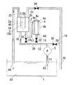
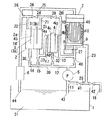
図1に本発明に係る浴槽水の水質改変装置の一例を示す。この浴槽水の水質改変装置には、後述する浴槽水31の流路に水流を発生させて流路中の浴槽水を移送する循環ポンプ5、有隔膜電解槽2及び内部に塩化ナトリウムが収容されている塩水供給槽4が配設されている。ここで有隔膜電解槽2は内部に隔膜45で隔てられた第一電極室2aと第二電極室2bが設けられ、この第一電極室2aと第二電極室2bにはそれぞれ不溶性電極板3が配設されている。第一電極室2aに配設されている不溶性電極板3は、基材がチタン、表面の電解面が白金−イリジウム混合物で形成された白金−イリジウム混合電極3aである。また第二電極室2bに配設されている不溶性電極板3は、基材がチタン、表面の電解面が白金で形成された白金電極3bである。また塩水供給槽4は、二重円筒構造を有し、内側の筒体である内筒4aに塩化ナトリウムを収納するようになっている。この内筒4aは上面が開口すると共に、側面が格子状に開口し、この開口部をメッシュにて覆っている。一方、外側の筒体である外筒4bは、蓋体4cが設けられており、蓋体4cを開くことにより、内部に内筒4aを収容し、あるいは脱離できる。塩水供給槽4に接続される流路のうち、塩水供給槽4に浴槽水31等を供給する流路はこの外筒4b内に、外筒4bの下部に設けられた流入口4dにて接続され、流路から外筒4b内に浴槽水31等が供給されると、内筒4a内の塩化ナトリウムがこの浴槽水31等に溶解して塩水が生成される。塩水供給槽4にて生成された塩水を導出する流路はこの外筒4bに、外筒4bの上部に設けられた流出口4eにて接続される。
【0017】
また更に浴槽水31が通る流路、及びこれらの流路の流通を開閉する、電磁弁等からなる開閉弁が配設されている。ここでいう浴槽水31には、浴槽水31に塩化ナトリウムを溶解して得られる塩水、並びにこの塩水や浴槽水31を電気分解して得られる酸性イオン水やアルカリ性イオン水が含まれる。
【0018】
浴槽水31が通る流路のうち、流入路11は上流側が浴槽1中の浴槽水31に配設されて、その上流側の端部が流入口43として開口しており、下流側が循環ポンプ5に接続されている。電解導入路12は上流側が循環ポンプ5に接続され、下流側において塩水槽路13と電解槽路30に分岐している。塩水槽路13の下流側は塩水供給槽4の流入口4dに接続されている。電解槽路30の下流側は第一電極室路14と第二電極室路15に分岐され、第一電極室路14の下流側は有隔膜電解槽2の第一電極室2aに、第二電極室路15の下流側は有隔膜電解槽2の第二電極室2bにそれぞれ接続されている。第一電極室導出路22の上流側は有隔膜電解槽2の第一電極室2aに接続され、下流側は流出路16の上流側に接続されている。流出路16の下流側は浴槽1内の浴槽水31に接続され、下流側の端部は流出口44として開口されている。また塩供給路17は上流側が塩水供給槽4の流出口4eに接続され、下流側は第二電極室路15の流路の途中に、第二電極室路15と合流するように接続されている。第二電極室導出路21の上流側は有隔膜電解槽2の第二電極室2bに接続され、下流側は排水導入路19の上流側に接続されている。排水導入路19の下流側は排水路18の上流側に接続されている。また浴槽水バイパス路20の上流側は電解導入路12の配管の途中に、電解導入路12から分岐するように接続され、下流側は排水路18の上流側に接続されている。排水路18の下流側は浴槽1外に導出されている。
【0019】
また開閉弁のうち、第1弁32は塩水槽路13に、第2弁33は第二電極室路15における塩供給路17の接続位置よりも上流側に、第3弁34は排水導入路19に、第4弁35は浴槽水バイパス路20にそれぞれ設けられ、各流路の流通を、この開閉弁の配設位置において開閉する。
【0020】
ここで、開閉弁の設置方法は上記のものに限るものではなく、例えば三方弁を用いることができる。
【0021】
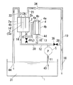
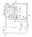
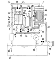
この浴槽水の水質改変装置の動作を図2〜4を示して説明する。ここでこれらの図面中で白抜きで示されている開閉弁は開状態の弁を、黒く塗りつぶして示されている開閉弁は閉状態の弁をそれぞれ示し、また流路中の矢印は各流路における浴槽水31の流れの向きを示す。
【0022】
浴槽水31をアルカリ性に水質改変する場合、まず図2に示すように、第1弁32、第2弁33、第3弁34、第4弁35が閉状態となり、この状態で循環ポンプ5が作動する。このとき循環ポンプ5の働きにより浴槽水31は流入路11、電解導入路12、電解槽路30、第一電極室路14、第一電極室導出路22、流出路16からなる循環流路を循環し、またそれに伴って有隔膜電解槽2の第一電極室2aに浴槽水31が供給され、第一電極室2a中の余剰の浴槽水31は第一電極室導出路22、流出路16を経由して浴槽1に返送される。
【0023】
次に図3に示すように、第1弁32、第3弁34が開状態、第2弁33、第4弁35が閉状態となり、この状態で引き続き循環ポンプ5が作動する。このとき、図2に示す循環流路の水流に加えて、電解導入路12から塩水槽路13を通って塩水供給槽4に導入され、塩水供給槽4から塩供給路17を通って有隔膜電解槽2の第二電極室2bに導入され、第二電極室2bから第二電極室導出路21、排水導入路19を経由して排水路18から浴槽1外に排出される水流が形成される。このとき塩水供給槽4内の塩化ナトリウムが、塩水槽路13から塩水供給槽4に供給された浴槽水31に溶解して塩水が生成し、この塩水が塩供給路17を通って第二電極室2bに供給され、第二電極室2b内の余剰の塩水は第二電極室導出路21、排水導入路19、排水路18を経由して浴槽1外に排出される。
【0024】
次に第1弁32、第2弁33、第3弁34、第4弁35が閉状態となって、再び図2に示すような状態となり、この状態で白金−イリジウム混合電極3aが陰極、白金電極3bが陽極となるように、この電極間に電圧が印可され、有隔膜電解槽2において電気分解により第一電極室2aにアルカリ性イオン水が、第二電極室2bに酸性イオン水が生成する。このとき有隔膜電解槽2において電気分解される浴槽水31には、塩化ナトリウムが添加されているので、浴槽水31の導電性が向上され、電気分解に必要な電力が低減されているものであり、また、有隔膜電解槽2内の浴槽水31中の塩化物イオン及びナトリウムイオンの濃度が向上されて、電気分解により陰極側で水酸化ナトリウム濃度の高いアルカリ性イオン水を生成すると共に、陽極側で塩酸濃度の高い酸性イオン水を生成するものである。ここで第一電極室2aには浴槽水が連続的に供給されると共に、余剰の浴槽水が浴槽1へ返送されているので、第一電極室2aにてアルカリ性イオン水となった浴槽水が浴槽1内に連続的に供給されることとなる。一方、第二電極室2b内には、酸性イオン水が保持される。第二電極室2bに設けられた白金電極3bは酸素発生効率が高いため、この酸性イオン水中では塩素の発生が抑制されている。
【0025】
次に電気分解の終了後、図4に示すように、第2弁33、第3弁34、第4弁35が開状態、第1弁32が閉状態となり、この状態で引き続き循環ポンプ5が作動する。このとき、循環流路の水流に加えて、電解槽路30から第二電極室路15を通って第二電極室2bに導入され、更に第二電極室2bから第二電極室導出路21、排水導入路19、排水路18を通って浴槽1外に排出される水流と、電解導入路12から分岐して浴槽水バイパス路20を経由し、排水路18に合流する水流が形成される。このとき第二電極室2b内の酸性イオン水は、第二電極室路15を経由して第二電極室2b内に導入される浴槽水31に押し出されて、第二電極室導出路21、排水導入路19、排水路18を経由して浴槽1外に排出される。このとき、浴槽水バイパス路20を経由して排水路18に、アルカリ性に水質改変された浴槽水31が供給されているので、酸性イオン水はこの浴槽水31により中和されると共に希釈された状態で排出される。この排水中の塩素濃度は低く抑えられており、有害で有臭の塩素ガスの発生が抑制され、また排出される酸性イオン水は、一旦第二電極室2b内に保持された後、中和及び希釈するために必要なだけの浴槽水31を混合して排出することができ、装置からの排水量が抑制され、浴槽水31の減少が抑制されている。
【0026】
次に、浴槽水31のアルカリ性への水質改変を停止する場合は循環ポンプが停止される。また浴槽水31を更に強いアルカリ性に水質改変する場合は、上記の動作が繰り返し行われる。
【0027】
また浴槽水31を酸性に水質改変する場合、流路の切り替えはアルカリ性に水質改変する場合と同様であるが、有隔膜電解槽2における電圧の印可の向きが逆になる。すなわち、まず図2に示すように、第1弁32、第2弁33、第3弁34、第4弁35が閉状態となり、この状態で循環ポンプ5が作動する。このとき循環ポンプ5の働きにより浴槽水31は流入路11、電解導入路12、電解槽路30、第一電極室路14、第一電極室導出路22、流出路16からなる循環流路を循環し、またそれに伴って有隔膜電解槽2の第一電極室2aに浴槽水31が供給され、第一電極室2a中の余剰の浴槽水31は第一電極室導出路22、流出路16を経由して浴槽1に返送される。
【0028】
次に図3に示すように、第1弁32、第3弁34が開状態、第2弁33、第4弁35が閉状態となり、この状態で引き続き循環ポンプ5が作動する。このとき、図2に示す循環流路の水流に加えて、電解導入路12から塩水槽路13を通って塩水供給槽4に導入され、塩水供給槽4から塩供給路17を通って有隔膜電解槽2の第二電極室2bに導入され、第二電極室2bから第二電極室導出路21、排水導入路19を経由して排水路18から浴槽1外に排出される水流が形成される。このとき塩水供給槽4内の塩化ナトリウムが、塩水槽路13から塩水供給槽4に供給された浴槽水31に溶解して塩水が生成し、この塩水が塩供給路17を通って第二電極室2bに供給され、第二電極室2b内の余剰の塩水は第二電極室導出路21、排水導入路19、排水路18を経由して浴槽1外に排出される。
【0029】
次に第1弁32、第2弁33、第3弁34、第4弁35が閉状態となって、再び図2に示すような状態となり、この状態で白金−イリジウム混合電極3aが陽極、白金電極3bが陰極となるように、この電極間に電圧が印可され、有隔膜電解槽2において電気分解により第一電極室2aに酸性イオン水が、第二電極室2bにアルカリ性イオン水が生成する。このとき第一電極室2aには浴槽水が連続的に供給されると共に、余剰の浴槽水31が浴槽1へ返送されているので、第一電極室2aにて酸性イオン水となった浴槽水31が浴槽1内に連続的に供給されることとなる。一方、第二電極室2b内には、アルカリ性イオン水が保持される。ここで第一電極室2aに設けられた白金−イリジウム混合電極3aは塩素発生効率が高いため、この酸性イオン水中では塩素が効率よく発生し、殺菌効果の高い酸性イオン水が生成される。
【0030】
次に電気分解の終了後、図4に示すように、第2弁33、第3弁34、第4弁35が開状態、第1弁32が閉状態となり、この状態で引き続き循環ポンプ5が作動する。このとき、循環流路の水流に加えて、電解槽路30から第二電極室路15を通って第二電極室2bに導入され、更に第二電極室2bから第二電極室導出路21、排水導入路19、排水路18を通って浴槽1外に排出される水流と、電解導入路12から分岐して浴槽水バイパス路20を経由し、排水路18に合流する水流が形成される。このとき第二電極室2b内のアルカリ性イオン水は、第二電極室路15を経由して第二電極室2b内に導入される浴槽水31に押し出されて、第二電極室導出路21、排水導入路19、排水路18を経由して浴槽1外に排出される。このとき、浴槽水バイパス路20を経由して排水路18に、酸性に水質改変された浴槽水31が供給されているので、アルカリ性イオン水はこの浴槽水31により有る程度中和されると共に希釈された状態で排出される。ここで排出されるアルカリ性イオン水は、一旦第二電極室2b内に保持された後、必要な分だけ中和、希釈されて排出されるものであり、浴槽1からの排水量が抑制され、浴槽水31の減少が抑制されている。
【0031】
次に、浴槽水31の酸性への水質改変を停止する場合は循環ポンプが停止される。また浴槽水31を更に強い酸性に水質改変する場合は、上記の動作が繰り返し行われる。
【0032】
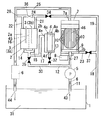
図5に本発明に係る浴槽水の水質改変装置の他例を示す。この浴槽水の水質改変装置には、図1と同様の循環ポンプ5、有隔膜電解槽2及び塩水供給槽4が配設されているほか、ヒータ6及び濾過槽7が配設されている。濾過槽7には、濾過槽7内を通る浴槽水31を濾過する、中空糸膜からなる濾過膜46が内装されている。この濾過膜46は濾過槽7内を水流の上流側と下流側とに仕切るように配置されている。濾過槽7内の、濾過膜46の上流側には、複数の吐水口10を有するノズル9が設けられている。このノズル9は、モータ8の働きにより濾過膜46の上流側の外周を回転するように構成され、この回転と同時に吐水口10から水流を濾過膜46の上流側の表面に吐出して濾過膜46を上流側において洗浄できるようになっている。また濾過槽7に接続される流路のうち、濾過槽7内に浴槽水31等を供給する流路は上記のノズル9に、濾過槽7内の濾過された浴槽水31等を導出する流路は、濾過槽7の下流側の上部に設けられた濾過水排出口7aにおいて、濾過膜46の洗浄に使用された後の水を濾過槽7外に導出する流路は、濾過槽7の上流側の下部に設けられた洗浄水排出口7bにおいて、それぞれ接続される。
【0033】
また更に浴槽水の水流が通る流路、及びこれらの流路の流通を開閉する、電磁弁等からなる開閉弁が配設されている。ここでいう浴槽水31には、浴槽水31に塩化ナトリウムを溶解して得られる塩水、並びにこの塩水や浴槽水31を電気分解して得られる酸性イオン水やアルカリ性イオン水が含まれる。
【0034】
浴槽水の流路のうち、流路流入路11は下流側が浴槽1中の浴槽水31に配設されて、その下流側の端部が流入口43として開口しており、上流側が循環ポンプ5に接続されている。電解導入路12は上流側が循環ポンプ5に接続され、下流側において塩水槽路13と電解槽路30に分岐している。塩水槽路13の下流側は塩水供給槽4の流入口4dに接続されている。電解槽路30の下流側は第一電極室路14と第二電極室路15に分岐され、第一電極室路14の下流側は有隔膜電解槽2の第一電極室2aに、第二電極室路15の下流側は有隔膜電解槽2の第二電極室2bにそれぞれ接続されている。第一電極室導出路22の上流側は有隔膜電解槽2の第一電極室2aに接続され、下流側はイオン水路26の上流側に接続され、イオン水路26の下流側は流出路16の上流側に接続されている。流出路16の下流側は浴槽1内の浴槽水31に接続され、下流側の端部は流出口44として開口されている。この流出路16にはヒータ6が配設されており、ヒータ6が作動している場合は流出路16を通る水流はヒータ6にて加熱される。また塩供給路17は上流側が塩水供給槽4の流出口4eに接続され、下流側は電解槽路30の流路の途中に、電解槽路30と合流するように接続されている。第二電極室導出路21の上流側は有隔膜電解槽2の第二電極室2bに接続され、下流側は排水導入路19の上流側に接続されている。排水導入路19の下流側は排水路18の上流側に接続されている。排水路18の下流側は浴槽1外に導出されている。洗浄水排出路23の上流側は濾過槽7の洗浄水排出口7bに接続され、下流側は排水路18の上流側に、排水導入路19と共に接続されている。またイオン水バイパス路24は第二電極室導出路21の下流側と第一電極室導出路22の下流側とを接続している。
【0035】
また開閉弁のうち、第1弁32は塩水槽路13に、第3弁34は排水導入路19に、第4弁35は電解槽路30に、第5弁36はイオン水バイパス路24に、第6弁37は洗浄水排出路23にそれぞれ設けられ、各流路の流通を、この開閉弁の配設位置において開閉する。
【0036】
ここで、イオン水路26の下流側は濾過槽7の上流側において濾過流路27や流入路11の途中に合流するように接続してもよく、浴槽1内に直接接続してもよい。
【0037】
この浴槽水の水質改変装置の動作を図6〜11を示して説明する。ここでこれらの図面中で白抜きで示されている開閉弁は開状態の弁を、黒く塗りつぶして示されている開閉弁は閉状態の弁をそれぞれ示し、また流路中の矢印は各流路における浴槽水31の流れの向きを示す。
【0038】
浴槽水31を濾過槽7にて浄化する場合は、図6に示すように、第1弁32、第3弁34、第4弁35、第5弁36、第6弁37が閉状態となり、この状態で循環ポンプ5が作動する。このとき循環ポンプ5の働きにより浴槽水31は流入路11、濾過流路27、濾過水路25、流出路16で構成される循環流路を循環する。このとき濾過流路27から濾過槽7に供給される浴槽水31は、ノズル9の吐水口10から濾過槽7の上流側に供給され、更に濾過膜46を通過して濾過槽7の下流側に導入されるものであり、濾過槽7にて入浴等により浴槽水31に混入した垢、埃、細菌等を濾過し、浴槽水31が浄化されて清潔に保つことができるものである。またこのとき流出路16を通過する浴槽水31の温度が所定の設定温度よりも低い場合は、ヒータ6が作動して浴槽水31が加熱される。
【0039】
浴槽水31をアルカリ性に水質改変する場合は、まず図7に示すように、第1弁32、第5弁36が開状態、第3弁34、第4弁35、第6弁37が閉状態となり、この状態で循環ポンプ5が作動する。このとき循環ポンプ5の働きにより浴槽水31は流入路11、電解導入路12、塩水槽路13、塩供給路17、電解槽路30、第一電極室路14、第二電極室路15、第一電極室導出路22、第二電極室導出路21、イオン水バイパス路24、イオン水路26、流出路16にて構成される循環流路と、流入路11、濾過流路27、濾過水路25、流出路16で構成される循環流路の、二系統の循環流路を循環する。流入路11、濾過流路27、濾過水路25、流出路16で構成される循環流路においては、図6の場合と同様に、濾過槽7において浴槽水31の浄化が行われる。また塩水供給槽4内の塩化ナトリウムが、塩水槽路13から塩水供給槽4に供給された浴槽水31に溶解して塩水が生成し、この塩水は塩供給路17、電解槽路30を経由し、第一電極室路14から有隔膜電解槽2の第一電極室2aに供給されると共に第二電極室路15から有隔膜電解槽2の第二電極室2bに供給され、第一電極室2a及び第二電極室2b中の余剰の塩水は第一電極室導出路22、第二電極室導出路21、イオン水路26、流出路16を経由して浴槽1に返送される。
【0040】
次に図8に示すように、第5弁36が開状態、第1弁32、第3弁34、第4弁35、第6弁37が閉状態となり、この状態で引き続き循環ポンプ5が作動する。このとき流入路11、濾過流路27、濾過水路25、流出路16で構成される循環流路は維持されて、濾過槽7において浴槽水31の浄化が引き続き行われる。この状態で白金−イリジウム混合電極3aが陰極、白金電極3bが陽極となるように、この電極間に電圧が印可され、有隔膜電解槽2において電気分解により第一電極室2aにアルカリ性イオン水が、第二電極室2bに酸性イオン水が生成する。ここで第二電極室2bに設けられた白金電極3bは酸素発生効率が高いため、この酸性イオン水中では塩素の発生が抑制されている。このように生成されたイオン水は有隔膜電解槽2内に保持される。
【0041】
次に電気分解の終了後に、図9に示すように、第3弁34、第4弁35、第6弁37が開状態、第1弁32、第5弁36が閉状態となり、この状態で引き続き循環ポンプ5が作動する。この状態でモータ8を作動させてノズル9を回転させる。このとき流入路11、電解導入路12、電解槽路30を経由して、第一電極室路14から第一電極室2a内に、第二電極室路15から第二電極室2b内に浴槽水31が導入される水流が発生する。第一電極室2a内のアルカリ性イオン水は、浴槽水31に押し出されて第一電極室導出路22、イオン水路26、流出路16を経由して流出口44から浴槽1内に供給されて、浴槽1内の浴槽水31をアルカリ性に水質改変する。また第二電極室2b内の酸性イオン水は、第二電極室導出路21、排水導入路19、排水路18を経由して浴槽1外に排出される。一方、濾過流路27を経由して濾過槽7に導入される浴槽水31は、回転するノズル9の吐水口10から濾過膜46に向けて吹き付けられ、この水流により濾過膜46の表面に付着した汚物がはぎ取られて濾過膜46が洗浄され、この汚物を含む洗浄後の浴槽水31は、水圧抵抗の高い濾過膜46を透過せずに洗浄水排出口7bを水圧抵抗の低い洗浄水排出路23を通過し、排水路18にて酸性イオン水と混合されて、浴槽1外に排出される酸性イオン水を希釈する。このとき酸性イオン水中の塩素が濾過槽洗浄後の浴槽水中に含まれる垢、埃、細菌等の有機物や無機物と反応して分解され、排水からの有害、有臭の塩素ガスの気化を抑制される。
【0042】
この場合、浴槽水31をアルカリ性に水質改変する動作と浴槽水31を浄化する動作が同時に行われるものである。また酸性イオン水は一旦第二電極室2b内に保持された後、必要な分だけ中和、希釈されて排出されるものであり、酸性イオン水を排出する際の浴槽水31の排出量が低減されているものであり、また酸性イオン水の希釈に、本来そのまま排出される濾過膜46を洗浄後の浴槽水31を用いているので、浴槽水31の排出量が更に低減されている。
【0043】
また浴槽水31を殺菌する場合は、まず図7に示すように、第1弁32、第5弁36が開状態、第3弁34、第4弁35、第6弁37が閉状態となり、この状態で循環ポンプ5が作動する。このとき循環ポンプ5の働きにより浴槽水31は流入路11、電解導入路12、塩水槽路13、塩供給路17、電解槽路30、第一電極室路14、第二電極室路15、第一電極室導出路22、第二電極室導出路21、イオン水バイパス路24、イオン水路26、流出路16にて構成される循環流路と、流入路11、濾過流路27、濾過水路25、流出路16で構成される循環流路の、二系統の循環流路を循環する。流入路11、濾過流路27、濾過水路25、流出路16で構成される循環流路においては、図6の場合と同様に、濾過槽7において浴槽水31の浄化が行われる。また塩水供給槽4内の塩化ナトリウムが、塩水槽路13から塩水供給槽4に供給された浴槽水31に溶解して塩水が生成し、この塩水は塩供給路17、電解槽路30を経由し、第一電極室路14から有隔膜電解槽2の第一電極室2aに供給されると共に第二電極室路15から有隔膜電解槽2の第二電極室2bに供給され、第一電極室2a及び第二電極室2b中の余剰の塩水は第一電極室導出路22、第二電極室導出路21、イオン水路26、流出路16を経由して浴槽1に返送される。
【0044】
次に図8に示すように、第5弁36が開状態、第1弁32、第3弁34、第4弁35、第6弁37が閉状態となり、この状態で引き続き循環ポンプ5が作動する。このとき流入路11、濾過流路27、濾過水路25、流出路16で構成される循環流路は維持されて、濾過槽7において浴槽水31の浄化が引き続き行われる。この状態で白金−イリジウム混合電極3aが陽極、白金電極3bが陰極となるように、この電極間に電圧が印可され、有隔膜電解槽2において電気分解により第一電極室2aに酸性イオン水が、第二電極室2bにアルカリ性イオン水が生成する。ここで第一電極室2aに設けられた白金−イリジウム混合電極3aは塩素発生効率が高いため、この酸性イオン水中では塩素が効率良く発生される。このように生成されたイオン水は有隔膜電解槽2内に保持される。
【0045】
次に電気分解の終了後に、図10に示すように、第4弁35、第5弁36が開状態、第1弁32、第3弁34、第6弁37が閉状態となり、この状態で引き続き循環ポンプ5が作動する。このとき流入路11、濾過流路27、濾過水路25、流出路16で構成される循環流路は維持されて、濾過槽7において浴槽水31の浄化が引き続き行われる。またこのとき流入路11、電解導入路12、電解槽路30を経由して、第一電極室路14から第一電極室2a内に、第二電極室路15から第二電極室2b内に浴槽水31が導入される水流が発生する。第一電極室2a内の酸性イオン水は浴槽水31に押し出されて第一電極室導出路22を経由してイオン水路26に至り、また第二電極室2b内のアルカリ性イオン水は、第二電極室導出路21、イオン水バイパス路24を経由してやはりイオン水路26に至るものであり、イオン水路26においてアルカリ性イオン水と酸性イオン水とが混合される。この混合水は中性又は弱アルカリ性のイオン水であり、また酸性イオン水が高濃度で塩素を含んでいたため、高い塩素濃度を有している。この混合水は、流出路16において、濾過槽7において浄化された後の浴槽水31と混合し、流出路16を通って流出口44から浴槽1内に供給され、混合水中の塩素にて浴槽1内の浴槽水31が殺菌される。この場合、浴槽水31の浄化と浴槽水31の殺菌とが同時に行われる。
【0046】
上記の浴槽水31をアルカリ性に水質改変しながら濾過膜46を洗浄する動作と、浴槽水31を殺菌する動作は、一回ずつ交互に、あるいはどちらか一方の動作が複数回繰り返して行われると共に他方の動作が一回行われるものであり、この場合、浴槽水31をアルカリ性に保ちながら、殺菌された衛生的な状態に保つことができ、しかも濾過膜46が洗浄されて濾過膜46の膜流量が保たれ、高い効率で濾過槽7による浴槽水31の浄化が行われるものである。
【0047】
また浴槽水31を酸性に水質改変する場合、まず図7に示すように、第1弁32、第5弁36が開状態、第3弁34、第4弁35、第6弁37が閉状態となり、この状態で循環ポンプ5が作動する。このとき循環ポンプ5の働きにより浴槽水31は流入路11、電解導入路12、電解槽路30、第一電極室路14、第二電極室路15、第一電極室導出路22、第二電極室導出路21、イオン水バイパス路24、イオン水路26、流出路16にて構成される循環流路と、流入路11、濾過流路27、濾過水路25、流出路16で構成される循環流路の、二系統の循環流路を循環する。流入路11、濾過流路27、濾過水路25、流出路16で構成される循環流路においては、図6の場合と同様に、濾過槽7において浴槽水31の浄化が行われる。また塩水供給槽4内の塩化ナトリウムが、塩水槽路13から塩水供給槽4に供給された浴槽水31に溶解して塩水が生成し、この塩水は塩供給路17、電解槽路30を経由し、第一電極室路14から有隔膜電解槽2の第一電極室2aに供給されると共に第二電極室路15から有隔膜電解槽2の第二電極室2bに供給され、第一電極室2a及び第二電極室2b中の余剰の塩水は第一電極室導出路22、第二電極室導出路21、イオン水路26、流出路16を経由して浴槽1に返送される。
【0048】
次に図8に示すように、第5弁36が開状態、第1弁32、第3弁34、第4弁35、第6弁37が閉状態となり、この状態で引き続き循環ポンプ5が作動する。このとき流入路11、濾過流路27、濾過水路25、流出路16で構成される循環流路は維持されて、濾過槽7において浴槽水31の浄化が引き続き行われる。この状態で白金−イリジウム混合電極3aが陽極、白金電極3bが陰極となるように、この電極間に電圧が印可され、有隔膜電解槽2において電気分解により第一電極室2aに酸性イオン水が、第二電極室2bにアルカリ性イオン水が生成する。ここで第一電極室2aに設けられた白金−イリジウム混合電極3aは塩素発生効率が高いため、この酸性イオン水中では塩素が効率良く発生される。このように生成されたイオン水は有隔膜電解槽2内に保持される。
【0049】
次に電気分解の終了後、図11に示すように、第1弁32、第5弁36が開状態、第3弁34、第4弁35、第6弁37が閉状態となり、この状態で引き続き循環ポンプ5が作動する。このとき流入路11、濾過流路27、濾過水路25、流出路16で構成される循環流路は維持されて、濾過槽7において浴槽水31の浄化が引き続き行われる。またこのとき流入路11、電解導入路12、電解槽路30を経由して、第一電極室路14から第一電極室2a内に、第二電極室路15から第二電極室2b内に浴槽水31が導入される水流が発生する。第一電極室2a内の酸性イオン水は、浴槽水31に押し出されて第一電極室導出路22、イオン水路26、流出路16を経由して流出口44から浴槽1内に供給されて、浴槽1内の浴槽水31を酸性に水質改変する。また第二電極室2b内のアルカリ性イオン水は、第二電極室導出路21、排水導入路19、排水路18を経由して浴槽1外に排出される。
【0050】
またこのとき図9に示すように、第6弁37を開状態とすると共に、この状態でモータ8を作動させてノズル9を回転させてもよい。この場合、濾過流路27を経由して濾過槽7に導入される浴槽水31は、回転するノズル9の吐水口10から濾過膜46に向けて吹き付けられ、この水流により濾過膜46の表面に付着した汚物がはぎ取られ、この汚物を含む洗浄後の浴槽水31は、水圧抵抗の高い濾過膜46を透過せずに洗浄水排出口7bを水圧抵抗の低い洗浄水排出路23を通過し、排水路18にてアルカリ性イオン水と混合されて、浴槽1外に排出されるアルカリ性イオン水を希釈する。
【0051】
上記の浴槽水の水質改変装置では、電気分解中においては、有隔膜電解槽2に浴槽水31が供給されないため、有隔膜電解槽2に供給される浴槽水31の量を低減して浴槽水31中に含まれる不純物やカルシウムによる電極表面や隔膜45の汚染を抑制することができる。
【0052】
図12に本発明に係る浴槽水の水質改変装置の更に他例を示す。この浴槽水の水質改変装置には、図5と同様の循環ポンプ5、有隔膜電解槽2、塩水供給槽濾過膜46及び濾過槽7が配設されている。
【0053】
また更に浴槽水の水流が通る流路、及びこれらの流路の流通を開閉する、電磁弁等からなる開閉弁が配設されている。ここでいう浴槽水31には、浴槽水31に塩化ナトリウムを溶解して得られる塩水、並びにこの塩水や浴槽水31を電気分解して得られる酸性イオン水やアルカリ性イオン水が含まれる。
【0054】
浴槽水31が通る流路のうち、流入路11は下流側が浴槽1中の浴槽水31に配設されて、その下流側の端部が流入口43として開口しており、上流側が循環ポンプ5に接続されている。電解導入路12は上流側が循環ポンプ5に接続され、下流側において塩水槽路13と電解槽路30に分岐している。塩水槽路13の下流側は塩水供給槽4の流入口4dに接続されている。電解槽路30の下流側は第一電極室路14と第二電極室路15に分岐され、第一電極室路14の下流側は有隔膜電解槽2の第一電極室2aに、第二電極室路15の下流側は有隔膜電解槽2の第二電極室2bにそれぞれ接続されている。第一電極室導出路22の上流側は有隔膜電解槽2の第一電極室2aに接続され、下流側はイオン水路26の上流側に接続され、イオン水路26の下流側は流出路16の上流側に接続されている。流出路16の下流側は浴槽1内の浴槽水31に接続され、下流側の端部は流出口44として開口されている。この流出路16にはヒータ6が配設されており、ヒータ6が作動している場合は流出路16を通る水流はヒータ6にて加熱される。また塩供給路17は上流側が塩水供給槽4の流出口4eに接続され、下流側は第二電極室路15の流路の途中に、第二電極室路15と合流するように接続されている。第二電極室導出路21の上流側は有隔膜電解槽2の第二電極室2bに接続され、下流側は洗浄イオン路28の上流側に接続されている。洗浄イオン路28の下流側は濾過流路27の配管の途中に濾過流路27と合流するように接続されている。洗浄水排出路23の上流側は濾過槽7の洗浄水排出口7bに接続され、下流側は排水路18の上流側に接続されている。浴槽水バイパス路29の上流側は流入路11の配管の途中に、流入路11から分岐するように接続されており、下流側は排水路18の上流側に、洗浄水排出路23と共に接続されている。排水路18の下流側は浴槽1外に導出されている。
【0055】
また開閉弁のうち、第1弁32は塩水槽路13に、第2弁33は第二電極室路15の塩供給路17との接続位置よりも上流側に、第5弁36はイオン水バイパス路24に、第7弁38は第一電極室路14に、第8弁39は洗浄イオン路28に、第9弁40は濾過流路27の洗浄イオン路28との接続位置よりも上流側に、第10弁41は浴槽水バイパス路29に、第11弁42は排水路18にそれぞれ設けられ、各流路の流通を、この開閉弁の配設位置において開閉する。
【0056】
ここでイオン水路26の下流側は、浴槽1内に直接接続してもよい。
【0057】
この浴槽水の水質改変装置の動作を図13〜21を示して説明する。ここでこれらの図面中で白抜きで示されている開閉弁は開状態の弁を、黒く塗りつぶして示されている開閉弁は閉状態の弁をそれぞれ示し、また流路中の矢印は各流路における浴槽水31の流れの向きを示す。
【0058】
浴槽水31を濾過槽7にて浄化する場合は、図13に示すように、第9弁40が開状態、第1弁32、第2弁33、第5弁36、第7弁38、第8弁39、第10弁41、第11弁42が閉状態となり、この状態で循環ポンプ5が作動する。このとき循環ポンプ5の働きにより浴槽水31は流入路11、濾過流路27、濾過水路25、流出路16で構成される循環流路を循環する。このとき濾過流路27から濾過槽7に供給される浴槽水31は、ノズル9の吐水口10から濾過槽7の上流側に供給され、更に濾過膜46を通過して濾過槽7の下流側に導入されるものであり、濾過槽7にて入浴等により浴槽水31に混入した垢、埃、細菌等を濾過し、浴槽水31が浄化されて清潔に保つことができるものである。またこのとき流出路16を通過する浴槽水31の温度が所定の設定温度よりも低い場合は、ヒータ6が作動して浴槽水31が加熱される。
【0059】
浴槽水31をアルカリ性に水質改変する場合は、まず図14に示すように、第1弁32、第5弁36、第9弁40が開状態、第2弁33、第7弁38、第8弁39、第10弁41、第11弁42が閉状態となり、この状態で循環ポンプ5が作動する。このとき循環ポンプ5の働きにより浴槽水31は流入路11、電解導入路12、塩水槽路13、塩供給路17、第二電極室路15、第二電極室導出路21、イオン水バイパス路24、イオン水路26、流出路16にて構成される循環流路と、流入路11、濾過流路27、濾過水路25、流出路16で構成される循環流路の、二系統の循環流路を循環する。流入路11、濾過流路27、濾過水路25、流出路16で構成される循環流路においては、図13の場合と同様に、濾過槽7において浴槽水31の浄化が行われる。また塩水供給槽4内の塩化ナトリウムが、塩水槽路13から塩水供給槽4に供給された浴槽水31に溶解して塩水が生成し、この塩水は塩供給路17、第二電極室路15から有隔膜電解槽2の第二電極室2bに供給され、第二電極室2b中の余剰の塩水は第一電極室導出路22、イオン水路26、流出路16を経由して浴槽1に返送される。
【0060】
次に図15に示すように、第5弁36、第9弁40が開状態、第1弁32、第2弁33、第7弁38、第8弁39、第10弁41、第11弁42が閉状態となり、この状態で引き続き循環ポンプ5が作動する。このとき流入路11、濾過流路27、濾過水路25、流出路16で構成される循環流路は維持されて、濾過槽7において浴槽水31の浄化が引き続き行われる。この状態で白金−イリジウム混合電極3aが陰極、白金電極3bが陽極となるように、この電極間に電圧が印可され、有隔膜電解槽2において電気分解により第一電極室2aにアルカリ性イオン水が、第二電極室2bに酸性イオン水が生成する。このように生成されたイオン水は有隔膜電解槽2内に保持される。
【0061】
次に電気分解の終了後、図16に示すように、第7弁38、第9弁40、第11弁42が開状態、第1弁32、第2弁33、第5弁36、第8弁39、第10弁41が閉状態となり、この状態で引き続き循環ポンプ5が作動する。このとき流入路11、電解導入路12、電解槽路30を経由して、第一電極室路14から第一電極室2a内に浴槽水31が導入される水流が発生する。第一電極室2a内のアルカリ性イオン水は、浴槽水31に押し出されて第一電極室導出路22、イオン水路26、流出路16を経由して流出口44から浴槽1内に供給されて、浴槽1内の浴槽水31をアルカリ性に水質改変する。一方、濾過流路27を経由して濾過槽7に導入される浴槽水31は、水圧抵抗の高い濾過膜46を透過せずに洗浄水排出口7bを通じて水圧抵抗の低い洗浄水排出路23を通過し、排水路18を通って浴槽1外に排出される。
【0062】
次に図17に示すように、第7弁38、第8弁39、第11弁42が開状態、第1弁32、第2弁33、第5弁36、第9弁40、第10弁41が閉状態となり、この状態で引き続き循環ポンプ5が作動する。このとき流入路11、電解導入路12、電解槽路30を経由して、第一電極室路14から第一電極室2a内に、第二電極室路15から第二電極室2b内に浴槽水31が導入される水流が発生する。第一電極室2a内のアルカリ性イオン水は、図16の場合と同様に、引き続き浴槽水31に押し出されて第一電極室導出路22、イオン水路26、流出路16を経由して流出口44から浴槽1内に供給されて、浴槽1内の浴槽水31をアルカリ性に水質改変する。また第二電極室2b内の酸性イオン水は、第二電極室導出路21、洗浄イオン路28、濾過流路27を経由して濾過槽7に導入される。酸性イオン水は濾過槽7に貯められ、濾過槽7内の余剰の酸性イオン水は、水圧抵抗の低い洗浄水排出路23を通過し、排水路18を通って浴槽1外に排出される。ここで、図16に示す動作を行わずに、図15に示す動作から直接図17に示す動作に移行することにより、有隔膜電解槽2からのアルカリ性イオン水と酸性イオン水の排出を同時に開始しても良い。
【0063】
次に図18に示すように、第9弁40、第10弁41が開状態、第1弁32、第2弁33、第5弁36、第7弁38、第8弁39、第11弁42が閉状態となり、この状態で引き続き循環ポンプ5が作動する。この状態でモータ8を作動させてノズル9を回転させる。このとき浴槽水バイパス路29、濾過流路27、洗浄水排出路23からなる閉じた循環流路が形成され、濾過槽7に貯められていた酸性イオン水がこの閉じた循環流路を循環する。この閉じた循環流路を循環する酸性イオン水は、濾過流路27を経由して濾過槽7に導入され、回転するノズル9の吐水口10から濾過膜46に向けて吹き付けられ、この水流により濾過膜46の表面に付着した汚物がはぎ取られる。この汚物を含む洗浄後の浴槽水31は、水圧抵抗の高い濾過膜46を透過せずに洗浄水排出口7bを水圧抵抗の低い洗浄水排出路23を通過し、浴槽水バイパス路29を経由して再び濾過流路27から濾過槽7に導入される。またこのとき酸性イオン水中の塩素にて濾過膜46に付着した有機物を分解除去すると共に、濾過膜46を酸性下におくことで濾過膜46に付着している金属塩が溶解する。
【0064】
次に図19に示すように、第9弁40、第11弁42が開状態、第1弁32、第2弁33、第5弁36、第7弁38、第8弁39、第10弁41が閉状態となり、この状態で引き続き循環ポンプ5が作動する。このとき、流入路11、濾過流路27、洗浄水排出路23、排水路18からなる流路が形成され、流出口44から導入される浴槽水31が、閉じた循環流路を循環していた、汚物を含む酸性イオン水を押し出して、排水路18を経由して浴槽1外に排出し、更にこの流路をすすいで洗浄する。その後、図13に示す通常の循環状態に復帰する。
【0065】
また浴槽水31を殺菌する場合は、まず図14に示すように、第1弁32、第5弁36、第9弁40が開状態、第2弁33、第7弁38、第8弁39、第10弁41、第11弁42が閉状態となり、この状態で循環ポンプ5が作動する。このとき循環ポンプ5の働きにより浴槽水31は流入路11、電解導入路12、塩水槽路13、塩供給路17、第二電極室路15、第二電極室導出路21、イオン水バイパス路24、イオン水路26、流出路16にて構成される循環流路と、流入路11、濾過流路27、濾過水路25、流出路16で構成される循環流路の、二系統の循環流路を循環する。流入路11、濾過流路27、濾過水路25、流出路16で構成される循環流路においては、図13の場合と同様に、濾過槽7において浴槽水31の浄化が行われる。また塩水供給槽4内の塩化ナトリウムが、塩水槽路13から塩水供給槽4に供給された浴槽水31に溶解して塩水が生成し、この塩水は塩供給路17、第二電極室路15から有隔膜電解槽2の第二電極室2bに供給され、第二電極室2b中の余剰の塩水は第一電極室導出路22、イオン水路26、流出路16を経由して浴槽1に返送される。
【0066】
次に図15に示すように、第1弁32、第5弁36、第9弁40が開状態、第2弁33、第7弁38、第8弁39、第10弁41、第11弁42が閉状態となり、この状態で引き続き循環ポンプ5が作動する。このとき流入路11、濾過流路27、濾過水路25、流出路16で構成される循環流路は維持されて、濾過槽7において浴槽水31の浄化が引き続き行われる。この状態で白金−イリジウム混合電極3aが陽極、白金電極3bが陰極となるように、この電極間に電圧が印可され、有隔膜電解槽2において電気分解により第一電極室2aに酸性イオン水が、第二電極室2bにアルカリ性イオン水が生成する。ここで第一電極室2aに設けられた白金−イリジウム混合電極3aは塩素の発生効率が高いため、この酸性イオン水中では塩素が効率よく発生される。このように生成されたイオン水は有隔膜電解槽2内に保持される。
【0067】
次に電気分解の終了後、図20に示すように、第2弁33、第7弁38、第1弁32、第9弁40が開状態、第5弁36、第8弁39、第10弁41、第11弁42が閉状態となり、この状態で引き続き循環ポンプ5が作動する。このとき流入路11、濾過流路27、濾過水路25、流出路16で構成される循環流路は維持されて、濾過槽7において浴槽水31の浄化が引き続き行われる。またこのとき流入路11、電解導入路12、電解槽路30を経由して、第一電極室路14から第一電極室2a内に、第二電極室路15から第二電極室2b内に浴槽水31が導入される水流が発生する。第一電極室2a内の酸性イオン水は浴槽水31に押し出されて第一電極室導出路22を経由してイオン水路26に至り、また第二電極室2b内のアルカリ性イオン水は、第二電極室導出路21、イオン水バイパス路24を経由してやはりイオン水路26に至るものであり、イオン水路26においてアルカリ性イオン水と酸性イオン水とが混合される。この混合水は中性又は弱アルカリ性のイオン水であり、また酸性イオン水が高濃度で塩素を含んでいたため、高い塩素濃度を有している。この混合水は、流出路16において、濾過槽7において浄化された後の浴槽水31と混合し、流出路16を通って流出口44から浴槽1内に供給され、混合水中の塩素にて浴槽1内の浴槽水31が殺菌される。この場合、浴槽水31の浄化と浴槽水31の殺菌とが同時に行われる。
【0068】
上記の浴槽水31をアルカリ性に水質改変しながら濾過膜46を洗浄する動作と、浴槽水31を殺菌する動作は、一回ずつ交互に、あるいはどちらか一方の動作が複数回繰り返して行われると共に他方の動作が一回行われるものであり、この場合、浴槽水31をアルカリ性に保ちながら、殺菌された衛生的な状態に保つことができ、しかも濾過膜46が洗浄されて濾過膜46の膜流量が保たれ、高い効率で濾過槽7による浴槽水31の浄化が行われるものである。
【0069】
また浴槽水31を酸性に水質改変する場合、まず図14に示すように、第1弁32、第5弁36、第9弁40が開状態、第2弁33、第7弁38、第8弁39、第10弁41、第11弁42が閉状態となり、この状態で循環ポンプ5が作動する。このとき循環ポンプ5の働きにより浴槽水31は流入路11、電解導入路12、塩水槽路13、塩供給路17、第二電極室路15、第二電極室導出路21、イオン水バイパス路24、イオン水路26、流出路16にて構成される循環流路と、流入路11、濾過流路27、濾過水路25、流出路16で構成される循環流路の、二系統の循環流路を循環する。流入路11、濾過流路27、濾過水路25、流出路16で構成される循環流路においては、図13の場合と同様に、濾過槽7において浴槽水31の浄化が行われる。また塩水供給槽4内の塩化ナトリウムが、塩水槽路13から塩水供給槽4に供給された浴槽水31に溶解して塩水が生成し、この塩水は塩供給路17、第二電極室路15から有隔膜電解槽2の第二電極室2bに供給され、第二電極室2b中の余剰の塩水は第一電極室導出路22、イオン水路26、流出路16を経由して浴槽1に返送される。
【0070】
次に図15に示すように、第1弁32、第5弁36、第9弁40が開状態、第2弁33、第7弁38、第8弁39、第10弁41、第11弁42が閉状態となり、この状態で引き続き循環ポンプ5が作動する。このとき流入路11、濾過流路27、濾過水路25、流出路16で構成される循環流路は維持されて、濾過槽7において浴槽水31の浄化が引き続き行われる。この状態で白金−イリジウム混合電極3aが陽極、白金電極3bが陰極となるように、この電極間に電圧が印可され、有隔膜電解槽2において電気分解により第一電極室2aに酸性イオン水が、第二電極室2bにアルカリ性イオン水が生成する。ここで第一電極室2aに設けられた白金−イリジウム混合電極3aは塩素の発生効率が高いため、この酸性イオン水中では塩素が効率よく発生される。このように生成されたイオン水は有隔膜電解槽2内に保持される。
【0071】
次に電気分解の終了後、図16に示すように、第7弁38、第9弁40、第11弁42が開状態、第1弁32、第2弁33、第5弁36、第8弁39、第10弁41が閉状態となり、この状態で引き続き循環ポンプ5が作動する。このとき流入路11、電解導入路12、電解槽路30を経由して、第一電極室路14から第一電極室2a内に浴槽水31が導入される水流が発生する。第一電極室2a内の酸性イオン水は、浴槽水31に押し出されて第一電極室導出路22、イオン水路26、流出路16を経由して流出口44から浴槽1内に供給されて、浴槽1内の浴槽水31を酸性に水質改変する。一方、濾過流路27を経由して濾過槽7に導入される浴槽水31は、水圧抵抗の高い濾過膜46を透過せずに洗浄水排出口7bを水圧抵抗の低い洗浄水排出路23を通過し、排水路18を通って浴槽1外に排出される。
【0072】
次に図17に示すように、第2弁33、第7弁38、第8弁39、第11弁42が開状態、第1弁32、第5弁36、第9弁40、第10弁41が閉状態となり、この状態で引き続き循環ポンプ5が作動する。このとき流入路11、電解導入路12、電解槽路30を経由して、第一電極室路14から第一電極室2a内に、第二電極室路15から第二電極室2b内に浴槽水31が導入される水流が発生する。第一電極室2a内の酸性イオン水は、図16の場合と同様に、引き続き浴槽水31に押し出されて第一電極室導出路22、イオン水路26、流出路16を経由して流出口44から浴槽1内に供給されて、浴槽1内の浴槽水31を酸性に水質改変する。また第二電極室2b内のアルカリ性イオン水は、第二電極室導出路21、洗浄イオン路28、濾過流路27を経由して濾過槽7に導入される。濾過槽7内のアルカリ性イオン水は水圧抵抗の低い洗浄水排出路23を通過し、排水路18を通って浴槽1外に排出される。ここで、図16に示す動作を行わずに、図15に示す動作から直接図17に示す動作に移行することにより、有隔膜電解槽2からのアルカリ性イオン水と酸性イオン水の排出を同時に開始しても良い。
【0073】
上記の浴槽水の水質改変装置では、電気分解中においては、有隔膜電解槽2に浴槽水31が供給されないため、有隔膜電解槽2に供給される浴槽水31の量を低減して浴槽水31中に含まれる不純物やカルシウムによる電極表面や隔膜45の汚染を抑制することができる。
【0074】
【発明の効果】
本発明の請求項1に係る浴槽水の水質改変装置は、有隔膜電解槽と、有隔膜電解槽内の隔膜にて隔てられた第一電極室と第二電極室のうちの第二電極室内に塩化ナトリウムを供給する塩水供給槽と、電気分解に供される浴槽水を浴槽から有隔膜電解槽に供給し、有隔膜電解槽にて電気分解により生成するアルカリ性イオン水と酸性イオン水のうち一方のイオン水を第一電極室から浴槽に供給すると共に他方のイオン水を第二電極室から浴槽外に排出する浴槽水の流路と、この浴槽水の流路に水流を発生させる循環ポンプとを具備し、循環ポンプは電解導入路、電解槽路を経由し、第一電極室路及び第二電極室路に分岐して第一電極室と第二電極室にそれぞれ接続され、塩水供給槽は電解導入路から分岐した塩水槽路に接続され更に塩供給路を経て第二電極室路に接続されているものであり、有隔膜電解槽内の浴槽水に塩化ナトリウムを添加して導電性を向上し、電気分解に必要な電力を低減することができ、また有隔膜電解槽内の浴槽水中の塩化物イオン及びナトリウムイオンの濃度が向上されて、電気分解により陰極側で水酸化ナトリウム濃度の高いアルカリ性イオン水を生成すると共に、陽極側で塩酸濃度の高い酸性イオン水を生成することができ、このようなイオン水を浴槽水のpHの改変に利用することができるものである。
【0075】
また本発明の請求項2に係る浴槽水の水質改変装置は、請求項1の構成に加えて、開閉弁を開閉することにより有隔膜電解槽における電気分解の進行中に、有隔膜電解槽にて電気分解により生成するアルカリ性イオン水と酸性イオン水のうち一方のイオン水を第一電極室から連続的に浴槽に供給し、有隔膜電解槽における電気分解の終了後に他方のイオン水を第二電極室から浴槽外に排出する浴槽水の流路を具備し、前記開閉弁として、塩水槽路の流通を開閉する開閉弁と、第二電極室路における塩供給路の接続位置よりも上流側の流通を開閉する開閉弁と、イオン水を第二電極室から浴槽外に排出する流路を開閉する開閉弁とを備えるものであり、イオン水を浴槽外に排出する際の排水量を低減して、浴槽内の浴槽水の急激な減少を抑制することができるものである。
【0076】
また本発明の請求項3に係る浴槽水の水質改変装置は、有隔膜電解槽と、有隔膜電解槽内の隔膜にて隔てられた第一電極室と第二電極室の両方の電極室内に塩化ナトリウムを供給する塩水供給槽と、開閉弁を開閉することにより電気分解に供される浴槽水を浴槽から有隔膜電解槽に供給し、有隔膜電解槽における電気分解終了後に、有隔膜電解槽にて電気分解により生成するアルカリ性イオン水と酸性イオン水のうちの一方のイオン水を第一電極室から浴槽に供給すると共に他方のイオン水を第二電極室から浴槽外に排出する浴槽水の流路と、この浴槽水の流路に水流を発生させる循環ポンプとを具備し、循環ポンプは電解導入路、電解槽路を経由し、第一電極室路及び第二電極室路に分岐して第一電極室と第二電極室にそれぞれ接続され、塩水供給槽は電解導入路から分岐した塩水槽路に接続され更に塩供給路を経て電解槽路に接続されるものであり、且つ前記開閉弁として塩水槽路の流通を開閉する開閉弁と、塩供給路との接続位置よりも上流側における電解槽路の流通を開閉する開閉弁とを備えるものであり、有隔膜電解槽内の浴槽水に塩化ナトリウムを添加して導電性を向上し、電気分解に必要な電力を低減することができ、また有隔膜電解槽内の浴槽水中の塩化物イオン及びナトリウムイオンの濃度が向上されて、電気分解により陰極側で水酸化ナトリウム濃度の高いアルカリ性イオン水を生成すると共に、陽極側で塩酸濃度の高い酸性イオン水を生成することができ、このようなイオン水を浴槽水のpHの改変に利用することができるものであり、またイオン水を浴槽外に排出する際の排水量を低減して、浴槽内の浴槽水の急激な減少を抑制することができるものであり、また有隔膜電解槽に供給される浴槽水の量を低減して浴槽水中に含まれる不純物やカルシウムによる電極表面や隔膜の汚染を抑制することができるものである。
【0077】
また本発明の請求項4に係る浴槽水の水質改変装置は、請求項1乃至3のいずれかの構成に加えて、開閉弁を開閉することにより有隔膜電解槽にて電気分解により生成するアルカリ性イオン水と酸性イオン水のうちのアルカリ性イオン水を浴槽に供給すると共に酸性イオン水を浴槽外に排出する動作と、電気分解により生成するアルカリ性イオン水と酸性イオン水の両方を浴槽に供給する動作とを一回ずつ交互に行うか、あるいは一方の動作を複数回行うのに対して他方の動作を一回行うものであり、イオン水を第一電極室から浴槽に供給する流路とイオン水を第二電極室から浴槽外に排出する流路とがイオン水バイパス路にて接続されており、且つ前記開閉弁として、イオン水を第二電極室から浴槽外に排出する流路を開閉する開閉弁と、イオン水バイパス路の流通を開閉する開閉弁とを備えるものであり、浴槽にアルカリ性イオン水を供給することにより浴槽中の浴槽水をアルカリ性に水質改変すると共に、アルカリ性イオン水と酸性イオン水が混合された中性又は弱アルカリ性で塩素濃度の高い混合水を浴槽に供給することにより浴槽中の浴槽水をアルカリ性に保ったまま塩素にて浴槽水を殺菌することができるものである。
【0078】
また本発明の請求項5に係る浴槽水の水質改変装置、請求項1乃至4のいずれかの構成に加えて、表面が白金−イリジウム混合物にて形成された白金−イリジウム混合物電極を有する第一電極室及び表面が白金にて形成された白金電極を有する第二電極室が設けられた有隔膜電解槽と、開閉弁を開閉することにより白金−イリジウム混合物電極を陰極、白金電極を陽極として電気分解を行ったときに有隔膜電解槽にて生成されるアルカリ性イオン水を浴槽に供給すると共に酸性イオン水を浴槽外に排出し、白金電極を陰極、白金−イリジウム混合物電極を陽極として電気分解を行ったときに有隔膜電解槽にて生成されるアルカリ性イオン水と酸性イオン水の両方を浴槽に供給する浴槽水の流路を具備し、イオン水を第一電極室から浴槽に供給する流路とイオン水を第二電極室から浴槽外に排出する流路とがイオン水バイパス路にて接続されており、且つ前記開閉弁として、イオン水を第二電極室から浴槽外に排出する流路を開閉する開閉弁と、イオン水バイパス路の流通を開閉する開閉弁とを備えるものであり、アルカリ性イオン水を浴槽に供給する場合は酸性イオン水を酸素発生効率の高い白金電極が配設された電極室で生成し、排出される酸性イオン水中の塩素濃度を低減して排水から有害で有臭の塩素ガスが気化し、雰囲気中に放出されることを防止することができるものであり、またアルカリ性イオン水と酸性イオン水が混合された中性又は弱アルカリ性の混合水を浴槽に供給する場合は、酸性イオン水を塩素の発生効率が高い白金−イリジウム混合物電極が配設された電極室にて生成し、混合水中の塩素濃度を向上して殺菌性能を向上することができるものであり、浴槽中の浴槽水をアルカリ性に保ったまま高濃度の塩素にて浴槽水を殺菌することができるものである。
【0079】
また本発明の請求項6に係る浴槽水の水質改変装置は、請求項1乃至5のいずれかの構成に加えて、表面が白金−イリジウム混合物にて形成された白金−イリジウム混合物電極を有する第一電極室及び表面が白金にて形成された白金電極を有する第二電極室が設けられた有隔膜電解槽と、開閉弁を開閉することにより白金−イリジウム混合物電極を陰極、白金電極を陽極として電気分解を行ったときに有隔膜電解槽にて生成されるアルカリ性イオン水を浴槽に供給すると共に酸性イオン水を浴槽外に排出し、白金電極を陰極、白金−イリジウム混合物電極を陽極として電気分解を行ったときに有隔膜電解槽にて生成されるアルカリ性イオン水を浴槽外に排出すると共に酸性イオン水を浴槽に供給する浴槽水の流路を具備し、イオン水を第一電極室から浴槽に供給する流路とイオン水を第二電極室から浴槽外に排出する流路とがイオン水バイパス路にて接続され、且つ前記開閉弁として、イオン水を第二電極室から浴槽外に排出する流路を開閉する開閉弁と、イオン水バイパス路の流通を開閉する開閉弁とを備えるものであり、アルカリ性イオン水を浴槽に供給する場合は酸性イオン水を酸素発生効率の高い白金電極が配設された電極室で生成し、排出される酸性イオン水中の塩素濃度を低減して排水から有害で有臭の塩素ガスが気化し、雰囲気中に放出されることを防止することができるものであり、また酸性イオン水を浴槽に供給する場合は、酸性イオン水を塩素の発生効率が高い白金−イリジウム混合物電極が配設された電極室にて生成し、酸性イオン水中の塩素濃度を向上して殺菌性能を向上することができるものであり、酸性イオン水にて浴槽中の浴槽水を酸性にすると共に高濃度の塩素にて浴槽水を殺菌することができるものである。
【0080】
また本発明の請求項7に係る水質改変装置は、請求項1乃至6のいずれかの構成に加えて、電解導入路の途中から分岐する浴槽水バイパス路がイオン水を第二電極室から浴槽外に排出する流路に接続され、且つ開閉弁として浴槽水バイパス路の流通を開閉するものを備え、前記開閉弁が開状態の場合に有隔膜電解槽にて生成されるアルカリ性イオン水と酸性イオン水のうち一方のイオン水を第一電極室から浴槽に供給すると共に第二電極室にて生成される他方のイオン水を浴槽水にて希釈した後に浴槽外に排出する浴槽水の流路を具備するものであり、排出されるイオン水を浴槽水にて希釈して中性に近づけた後に排出することができ、特に酸性イオン水を排出する場合は浴槽水にて希釈して中性に近づけることにより排水からの有害、有臭の塩素ガスの気化を抑制することができるものである。
また本発明の請求項8に係る浴槽水の水質改変装置は、請求項1乃至7のいずれかの構成に加えて、浴槽水を浄化する濾過槽と、濾過槽の上流側が電解導入路の途中から分岐する濾過流路にて接続され、濾過槽の下流側が濾過水路にてイオン水を第一電極室から浴槽に供給する流路に接続され、濾過槽の洗浄水排出口が洗浄水排出路にてイオン水を第二電極室から浴槽外に排出する流路に接続され、且つ開閉弁として洗浄水排出路の流通を開閉するものを備え、前記開閉弁が開状態の場合に濾過槽に濾過槽の洗浄用水として浴槽水を濾過流路から供給し、有隔膜電解槽にて生成されるアルカリ性イオン水と酸性イオン水のうち一方のイオン水を第一電極室から浴槽に供給すると共に第二電極室にて生成される他方のイオン水を洗浄水排出口から排出される濾過槽の洗浄後の浴槽水にて希釈した後に浴槽外に排出する浴槽水の流路を具備するものであり、濾過槽にて入浴等により浴槽水に混入した垢、埃、細菌等を濾過して、浴槽水を清潔に保つことができるものであり、またこの濾過槽を浴槽水にて洗浄することができるものであり、また濾過槽の洗浄に使用された浴槽水にて、排出するイオン水を希釈して中性に近づけた後に排出することができ、イオン水と濾過槽洗浄後の浴槽水を別々に排出する場合よりも排水量を低減して浴槽中の浴槽水の急激な減少を抑制することができ、また特に酸性イオン水を排出する場合は、この酸性イオン水中の塩素が濾過槽洗浄後の浴槽水中に含まれる垢、埃、細菌等の有機物や無機物と反応して分解され、排水からの有害、有臭の塩素ガスの気化を抑制することができるものである。
【0081】
また本発明の請求項9に係る浴槽水の水質改変装置は、請求項1乃至8のいずれかの構成に加えて、浴槽水を浄化する濾過槽を具備し、濾過槽の上流側が電解導入路の途中から分岐する濾過流路にて接続され、濾過槽の下流側が濾過水路にてイオン水を第一電極室から浴槽に供給する流路に接続されているものであり、濾過槽にて入浴等により浴槽水に混入した垢、埃、細菌等を濾過して、浴槽水を清潔に保つことができるものである。
【0082】
また本発明の請求項10に係る水質改変装置は、請求項9の構成に加えて、濾過膜として中空糸膜を備える濾過槽を具備すると共に、イオン水を第二電極室から浴槽外に排出する浴槽水の流路が、濾過流路に接続された後に濾過槽の洗浄水排出口から浴槽外に導出され、濾過槽に濾過槽の洗浄用水として有隔膜電解槽の第二電極室にて生成された酸性イオン水を供給する浴槽水の流路を具備するものであり、酸性イオン水中の塩素にて中空糸膜に付着した有機物を分解除去すると共に、中空糸膜を酸性下におくことで中空糸膜に付着している金属塩を溶解して排出することができ、濾過槽の洗浄性を向上することができるものである。
【図面の簡単な説明】
【図1】本発明の実施の形態の一例を示す概略図である。
【図2】同上の動作を示す概略図である。
【図3】同上の他の動作を示す概略図である。
【図4】同上の更に他の動作を示す概略図である。
【図5】本発明の実施の形態の他例を示す概略図である。
【図6】同上の動作を示す概略図である。
【図7】同上の他の動作を示す概略図である。
【図8】同上の更に他の動作を示す概略図である。
【図9】同上の更に他の動作を示す概略図である。
【図10】同上の更に他の動作を示す概略図である。
【図11】同上の更に他の動作を示す概略図である。
【図12】本発明の実施の形態の更に他例を示す概略図である。
【図13】同上の動作を示す概略図である。
【図14】同上の他の動作を示す概略図である。
【図15】同上の更に他の動作を示す概略図である。
【図16】同上の更に他の動作を示す概略図である。
【図17】同上の更に他の動作を示す概略図である。
【図18】同上の更に他の動作を示す概略図である。
【図19】同上の更に他の動作を示す概略図である。
【図20】同上の更に他の動作を示す概略図である。
【図21】同上の更に他の動作を示す概略図である。
【符号の説明】
1 浴槽
2 有隔膜電解槽
3a 白金−イリジウム混合物電極
3b 白金電極
4 塩水供給槽
5 循環ポンプ
7 濾過槽
31 浴槽水
45 隔膜
46 濾過膜[0001]
BACKGROUND OF THE INVENTION
The present invention relates to a water quality modification device for bath water that adjusts the pH of bath water.
[0002]
[Prior art]
Various devices have been proposed in the past to electrolyze and circulate the hot water in the bath to sterilize the warm water with acidic ionic water, the astrogen effect, or the treatment effect of alkaline ionic water. For example, there is one disclosed in JP-A-4-312461. The apparatus disclosed in this publication includes a heat retaining means for heating and keeping warm water in a bathtub, and an electrolysis means for electrolyzing water to produce acidic ion water and alkaline ion water, Water and alkaline ionized water can be appropriately refluxed in the bathtub.
[0003]
[Problems to be solved by the invention]
However, such a conventional technique has the following problems.
(1) Since the bath water with low electrical conductivity is electrolyzed, a high voltage must be applied between the electrodes in order to pass the current necessary for electrolysis, resulting in high power costs. .
(2) Since the ionic water which is not sent into the bathtub is continuously discharged out of the bathtub, the amount of drainage is increased and the decrease in the bathtub water is severe.
(3) While supplying alkaline ionic water to the bathtub, since the alkaline ionic water does not contain chlorine, the hot water in the bathtub could not be sterilized, and there was a sanitary problem.
(4) When acid ionic water is drained, there is a problem that harmful and odorous chlorine gas in the acid ionic water is vaporized and released into the atmosphere.
[0004]
This invention is made | formed in view of said point, and it aims at providing the water quality modification | change apparatus of the bathtub water which can solve the said subject.
[0005]
[Means for Solving the Problems]
The water quality modification device for bathtub water according to claim 1 of the present invention includes a diaphragm electrolytic cell 2 and a diaphragm electrolytic cell 2.Separated by inner diaphragm 45Of the first electrode chamber 2a and the second electrode chamber 2b, the second electrode chamber 2bSalt water supply tank 4 for supplying sodium chloride therein and bathtub water 31 for electrolysis are supplied from bathtub 1 to diaphragm membrane electrolytic tank 2, and alkaline ionized water generated by electrolysis in diaphragm membrane electrolytic tank 2 And one of the acid ion waterFrom the first electrode chamber 2aSupply the other ionic water to the bathtub 1From the second electrode chamber 2bBathtub1It has a flow path of bathtub water discharged outside, and a circulation pump 5 that generates a water flow in the flow path of the bathtub water.The circulation pump 5 branches to the first electrode chamber path 14 and the second electrode chamber path 15 via the electrolytic introduction path 12 and the electrolytic tank path 30, and is connected to the first electrode chamber 2a and the second electrode chamber 2b, respectively. The salt water supply tank 4 is connected to the salt water tank path 13 branched from the electrolytic introduction path 12 and further connected to the second electrode chamber path 15 via the salt supply path 17.It is characterized by this.
[0006]
Moreover, in addition to the structure of Claim 1, the water quality modification device for bathtub water according to Claim 2 of the present invention,By opening and closing the on-off valveWhile the electrolysis in the diaphragm electrolytic cell 2 is in progress, one of the ionic water of alkaline ionized water and acidic ionic water generated by electrolysis in the diaphragm electrolytic cell 2 isFrom the first electrode chamber 2aContinuously supplied to the bathtub 1, and after the electrolysis in the diaphragm cell 2 is completed, the other ionized water is supplied.From the second electrode chamber 2bIt has a flow path for bathtub water to be discharged outside the bathtub 1As the on-off valve, an on-off valve for opening and closing the circulation of the salt water tank passage 13, an on-off valve for opening and closing the passage upstream of the connection position of the salt supply passage 17 in the second electrode chamber passage 15, An on-off valve that opens and closes a flow path that discharges from the two-electrode chamber 2b to the outside of the bathtub 1It is characterized by this.
[0007]
Moreover, the water quality modification device for bathtub water according to claim 3 of the present invention was separated by the diaphragm electrolytic cell 2 and the diaphragm 45 in the diaphragm electrolytic cell 2.Between the first electrode chamber 2a and the second electrode chamber 2b.Both electricveryA salt water supply tank 4 for supplying sodium chloride into the room;By opening and closing the on-off valveBath water 31 to be subjected to electrolysis is supplied from the bathtub 1 to the diaphragm electrolyzer 2, and after the electrolysis in the diaphragm electrolyzer 2 is completed, alkaline ionized water and acidity generated by electrolysis in the diaphragm electrolyzer 2 Ion water of one of the ionic waterFrom the first electrode chamber 2aSupply the other ionic water to the bathtub 1From the second electrode chamber 2bIt comprises a flow path of bathtub water discharged outside the bathtub 1 and a circulation pump 5 that generates a water flow in the flow path of the bathtub water.The circulation pump 5 branches to the first electrode chamber path 14 and the second electrode chamber path 15 via the electrolytic introduction path 12 and the electrolytic tank path 30, and is connected to the first electrode chamber 2a and the second electrode chamber 2b, respectively. The salt water supply tank 4 is connected to the salt water tank path 13 branched from the electrolysis introduction path 12, is further connected to the electrolytic tank path 30 via the salt supply path 17, and the circulation of the salt water tank path 13 as the on-off valve. And an opening / closing valve for opening / closing the flow of the electrolytic cell path 30 upstream of the connection position with the salt supply path 17.It is characterized by this.
[0008]
Moreover, in addition to the structure in any one of Claims 1 thru | or 3, the water quality modification apparatus of the bathtub water which concerns on Claim 4 of this invention,By opening and closing the on-off valveIt produces | generates by the operation | movement which supplies the alkaline ion water of the alkaline ion water produced | generated by electrolysis in the diaphragm membrane electrolytic cell 2 and acidic ion water to the bathtub 1, and discharges acidic ion water out of the bathtub 1, and electrolysis The operation of supplying both alkaline ionized water and acidic ionized water to the bathtub 1 is alternately performed once, or one operation is performed a plurality of times while the other operation is performed once.The flow path for supplying ionic water from the first electrode chamber 2a to the bathtub 1 and the flow path for discharging ionic water from the second electrode chamber 2b to the outside of the bathtub 1 are connected by an ionic water bypass path 24, The open / close valve includes an open / close valve that opens and closes a flow path for discharging ionic water from the second electrode chamber 2 b to the outside of the bathtub 1, and an open / close valve that opens and closes the flow of the ionic water bypass path 24.It is characterized by this.
[0009]
Moreover, the water quality modification device for bathtub water according to claim 5 of the present invention has a platinum-iridium mixture electrode 3a having a surface formed of a platinum-iridium mixture in addition to the structure of any one of claims 1 to 4. DaiichiveryA second electrode having a chamber 2a and a platinum electrode 3b having a surface formed of platinum.veryA diaphragm electrolytic cell 2 provided with a chamber 2b;By opening and closing the on-off valveWhen electrolysis is performed using the platinum-iridium mixture electrode 3a as a cathode and the platinum electrode 3a as an anode, alkaline ionized water generated in the diaphragm membrane electrolytic cell 1 is supplied to the bathtub 1 and acidic ionized water is discharged outside the bathtub 1. It discharges, and supplies both the alkaline ion water and acidic ion water which are produced | generated in the diaphragm membrane electrolytic cell 2 when electrolyzing using the platinum electrode 3b as a cathode and the platinum-iridium mixture electrode 3a as an anode is supplied to the bathtub 1 Bathtub water flow pathA flow path for supplying ionic water from the first electrode chamber 2a to the bathtub 1 and a flow path for discharging ionic water from the second electrode chamber 2b to the outside of the bathtub 1 are connected by an ionic water bypass path 24, and As the opening / closing valve, an opening / closing valve for opening / closing a flow path for discharging ionic water from the second electrode chamber 2b to the outside of the bathtub 1 and an opening / closing valve for opening / closing the flow of the ionic water bypass path 24 are provided.It is characterized by this.
[0010]
Moreover, the water quality modification device for bathtub water according to claim 6 of the present invention has a platinum-iridium mixture electrode 3a having a surface formed of a platinum-iridium mixture in addition to the structure of any one of claims 1 to 5. DaiichiveryA second electrode having a chamber 2a and a platinum electrode 3b having a surface formed of platinum.veryA diaphragm electrolytic cell 2 provided with a chamber 2b;By opening and closing the on-off valveWhen electrolysis is performed using the platinum-iridium mixture electrode 3a as a cathode and the platinum electrode 3b as an anode, alkaline ionized water generated in the diaphragm membrane electrolytic cell 2 is supplied to the bathtub 1 and acidic ionized water is discharged outside the bathtub 1. The alkaline ionized water generated in the diaphragm membrane electrolytic cell 2 when the electrolysis is performed using the platinum electrode 3b as the cathode and the platinum-iridium mixture electrode 3a as the anode is discharged out of the bathtub 1 and the acidic ionized water is discharged. It has a flow path for bathtub water supplied to the bathtub 1A flow path for supplying ionic water from the first electrode chamber 2a to the bathtub 1 and a flow path for discharging ionic water from the second electrode chamber 2b to the outside of the bathtub 1 are connected by an ionic water bypass path 24, and the opening and closing are performed. As a valve, an open / close valve that opens and closes a flow path for discharging ionic water from the second electrode chamber 2b to the outside of the bathtub 1 and an open / close valve that opens and closes the flow of the ionic water bypass path 24 are provided.It is characterized by this.
[0011]
Moreover, in addition to the structure in any one of Claims 1 thru | or 6, the water quality modification apparatus which concerns on Claim 7 of this invention,The bathtub water bypass path 20 branched from the middle of the electrolytic introduction path 12 is connected to a flow path for discharging ionic water from the second electrode chamber 2b to the outside of the bathtub 1, and opens and closes the circulation of the bathtub water bypass path 20 as an on-off valve. When the on-off valve is openOne of the alkaline ionized water and the acidic ionized water generated in the diaphragm membrane electrolytic cell 2 isFrom the first electrode chamber 2aWhile supplying to bathtub 1It is generated in the second electrode chamber 2bThe other ionic water is diluted with the bath water, and then the bath water channel for discharging the bath water to the outside of the bath 1 is provided.
[0012]
Moreover, in addition to the structure in any one of Claims 1 thru | or 7, the filtration tank 7 which purifies the bathtub water 31 in addition to the structure of the bathtub water which concerns on Claim 8 of this invention,A flow in which the upstream side of the filtration tank 7 is connected by a filtration flow path 27 branched from the middle of the electrolytic introduction path 12, and the downstream side of the filtration tank 7 is a flow for supplying ionic water from the first electrode chamber 2 a to the bathtub 1 in the filtration water path 25. The washing water discharge port 7b of the filtration tank 7 is connected to a flow path for discharging ion water from the second electrode chamber 2b to the outside of the bathtub 1 in the washing water discharge path 23, and the washing water is discharged as an on-off valve. Provided with a means for opening and closing the flow of the passage 23, when the on-off valve is openBath water 31 is used as cleaning water for the filtration tank 7 in the filtration tank 7.From the filtration channel 27One of the alkaline ionized water and the acidic ionized water generated in the diaphragm cell 2 is supplied.From the first electrode chamber 2aWhile supplying to bathtub 1It is generated in the second electrode chamber 2bThe other ionized waterDischarged from the washing water outlet 7bThe filter tank 7 is provided with a flow path for bath water that is diluted with the bath water 31 after being washed and discharged to the outside of the bath 1.
[0013]
The bathtub water quality modifying device according to claim 9 of the present invention includes a filtration tank 7 for purifying the bathtub water 31 in addition to the structure of any one of claims 1 to 8.The upstream side of the filtration tank 7 is connected by a filtration flow path 27 that branches from the middle of the electrolytic introduction path 12, and the downstream side of the filtration tank 7 supplies ionic water from the first electrode chamber 2 a to the bathtub 1 through the filtration water path 25. Connected to the flow pathIt is characterized by this.
[0014]
Moreover, the water quality modification device according to claim 10 of the present invention includes a filtration tank 7 having a hollow fiber membrane as the filtration membrane 46 in addition to the configuration of claim 9.The bath water channel for discharging ionic water from the second electrode chamber 2b to the outside of the bathtub 1 is connected to the filtration channel 27 and then the washing water outlet 7b of the filtration tank 7 to the outside of the bathtub 1 Derived,Diaphragm electrolysis tank 2 as filtration tank 7 cleaning waterSecond electrode chamber 2bBath water flow to supply acidic ion water generated inThe roadIt is characterized by comprising.
[0015]
DETAILED DESCRIPTION OF THE INVENTION
Embodiments of the present invention will be described below.
[0016]
FIG. 1 shows an example of a water quality modifying device for bathtub water according to the present invention. In this bathtub water quality modifying device, a circulation pump 5 that generates a water flow in the flow path of the bathtub water 31 to be described later and transfers the bathtub water in the flow path, the diaphragm electrolyzer 2, and sodium chloride are contained therein. A salt water supply tank 4 is provided. Here, the diaphragm cell 2 is provided with a first electrode chamber 2a and a second electrode chamber 2b separated by a diaphragm 45, and the first electrode chamber 2a and the second electrode chamber 2b are respectively provided with an insoluble electrode plate 3. Is arranged. The insoluble electrode plate 3 disposed in the first electrode chamber 2a is a platinum-iridium mixed electrode 3a in which a base material is titanium and a surface electrolytic surface is formed of a platinum-iridium mixture. The insoluble electrode plate 3 disposed in the second electrode chamber 2b is a platinum electrode 3b in which a base material is titanium and a surface electrolytic surface is formed of platinum. Moreover, the salt water supply tank 4 has a double cylinder structure, and accommodates sodium chloride in an inner cylinder 4a which is an inner cylinder. The inner cylinder 4a has an upper surface opened and side surfaces opened in a lattice shape, and the opening is covered with a mesh. On the other hand, the outer cylinder 4b, which is an outer cylinder, is provided with a lid 4c. By opening the lid 4c, the inner cylinder 4a can be accommodated or removed. Of the flow paths connected to the salt water supply tank 4, the flow path for supplying the bath water 31 and the like to the salt water supply tank 4 is connected to the outer cylinder 4b at the inlet 4d provided at the lower part of the outer cylinder 4b. When the bathtub water 31 or the like is supplied from the flow path into the outer cylinder 4b, sodium chloride in the inner cylinder 4a is dissolved in the bathtub water 31 or the like to generate salt water. A flow path for deriving the salt water generated in the salt water supply tank 4 is connected to the outer cylinder 4b at an outlet 4e provided at the upper part of the outer cylinder 4b.
[0017]
Further, a flow path through which the bathtub water 31 passes and an open / close valve such as an electromagnetic valve for opening and closing the flow of these flow paths are provided. The bath water 31 here includes salt water obtained by dissolving sodium chloride in the bath water 31, and acidic ion water and alkaline ion water obtained by electrolyzing the salt water and the bath water 31.
[0018]
Among the flow paths through which the bathtub water 31 passes, the upstream side of the inflow path 11 is disposed in the bathtub water 31 in the bathtub 1, the upstream end thereof is opened as the inflow port 43, and the downstream side is the circulation pump 5. It is connected to the. The electrolysis introduction path 12 is connected to the circulation pump 5 on the upstream side, and branches into a salt water tank path 13 and an electrolysis tank path 30 on the downstream side. The downstream side of the salt water tank path 13 is connected to the inlet 4 d of the salt water supply tank 4. The downstream side of the electrolytic cell path 30 is branched into a first electrode chamber path 14 and a second electrode chamber path 15, and the downstream side of the first electrode chamber path 14 is connected to the first electrode chamber 2 a of the diaphragm membrane electrolytic cell 2. The downstream side of the electrode chamber path 15 is connected to the second electrode chamber 2b of the diaphragm membrane electrolytic cell 2, respectively. The upstream side of the first electrode chamber lead-out path 22 is connected to the first electrode chamber 2 a of the diaphragm electrolytic cell 2, and the downstream side is connected to the upstream side of the outflow path 16. The downstream side of the outflow path 16 is connected to the bathtub water 31 in the bathtub 1, and the downstream end is opened as an outlet 44. The salt supply path 17 is connected to the outlet 4e of the salt water supply tank 4 on the upstream side, and connected to the second electrode chamber path 15 in the middle of the flow path of the second electrode chamber path 15 on the downstream side. Yes. The upstream side of the second electrode chamber lead-out path 21 is connected to the second electrode chamber 2 b of the diaphragm electrolytic cell 2, and the downstream side is connected to the upstream side of the drainage introduction path 19. The downstream side of the drainage introduction channel 19 is connected to the upstream side of the drainage channel 18. Further, the upstream side of the bathtub water bypass path 20 is connected to branch from the electrolytic introduction path 12 in the middle of the piping of the electrolytic introduction path 12, and the downstream side is connected to the upstream side of the drainage path 18. The downstream side of the drainage channel 18 is led out of the bathtub 1.
[0019]
Among the on-off valves, the first valve 32 is in the salt water tank passage 13, the second valve 33 is upstream of the connection position of the salt supply passage 17 in the second electrode chamber passage 15, and the third valve 34 is in the drain introduction passage. 19, the fourth valve 35 is provided in the bathtub water bypass passage 20, and opens and closes the flow of each flow path at the position where the on-off valve is provided.
[0020]
hereOpenHow to install the valveIsFor example, a three-way valve can be used.
[0021]
The operation of this bathtub water quality modification device will be described with reference to FIGS. Here, the open / close valves shown in white in these drawings indicate the open valves, the open / close valves shown in black indicate the closed valves, and the arrows in the flow paths indicate the flow paths. The direction of the flow of the bathtub water 31 in the road is shown.
[0022]
When the water quality of the bath water 31 is changed to alkaline, first, as shown in FIG. 2, the first valve 32, the second valve 33, the third valve 34, and the fourth valve 35 are closed, and in this state, the circulation pump 5 is turned on. Operate. At this time, the circulation of the bathtub water 31 by the action of the circulation pump 5 causes the circulation flow path including the inflow path 11, the electrolytic introduction path 12, the electrolytic bath path 30, the first electrode chamber path 14, the first electrode chamber outlet path 22, and the outflow path 16. Accordingly, the bath water 31 is supplied to the first electrode chamber 2a of the diaphragm electrolyzer 2, and the excess bath water 31 in the first electrode chamber 2a is supplied to the first electrode chamber outlet passage 22 and the outflow passage 16. Returned to bathtub 1 via
[0023]
Next, as shown in FIG. 3, the first valve 32 and the third valve 34 are opened, the second valve 33 and the fourth valve 35 are closed, and the circulation pump 5 continues to operate in this state. At this time, in addition to the water flow in the circulation channel shown in FIG. 2, the separation membrane is introduced from the electrolytic introduction path 12 through the salt water tank path 13 to the salt water supply tank 4 and from the salt water supply tank 4 through the salt supply path 17. A water flow is formed which is introduced into the second electrode chamber 2b of the electrolytic cell 2 and discharged from the drainage channel 18 to the outside of the bathtub 1 through the second electrode chamber 2b and the drainage introduction channel 19 from the second electrode chamber 2b. The At this time, the sodium chloride in the salt water supply tank 4 is dissolved in the bath water 31 supplied from the salt water tank path 13 to the salt water supply tank 4 to generate salt water, and this salt water passes through the salt supply path 17 to the second electrode. The excess salt water in the second electrode chamber 2 b is discharged to the outside of the bathtub 1 via the second electrode chamber lead-out path 21, the drainage introduction path 19 and the drainage path 18.
[0024]
Next, the first valve 32, the second valve 33, the third valve 34, and the fourth valve 35 are closed, and the state again becomes as shown in FIG. 2. In this state, the platinum-iridium mixed electrode 3a is the cathode, A voltage is applied between the electrodes so that the platinum electrode 3b becomes an anode, and alkaline ionized water is generated in the first electrode chamber 2a and acidic ionized water is generated in the second electrode chamber 2b by electrolysis in the diaphragm membrane electrolytic cell 2. To do. At this time, sodium chloride is added to the bathtub water 31 that is electrolyzed in the diaphragm electrolyzer 2, so that the conductivity of the bathtub water 31 is improved and the electric power necessary for electrolysis is reduced. In addition, the concentration of chloride ions and sodium ions in the bath water 31 in the diaphragm electrolytic cell 2 is improved, and alkaline ionized water having a high sodium hydroxide concentration is generated on the cathode side by electrolysis. It produces acidic ionic water with a high hydrochloric acid concentration on the side. Here, the bathtub water continuously supplied to the first electrode chamber 2a and the excess bathtub water is returned to the bathtub 1, so that the bathtub water that has become alkaline ionized water in the first electrode chamber 2a is obtained. It will be continuously supplied into the bathtub 1. On the other hand, acidic ion water is held in the second electrode chamber 2b. Since the platinum electrode 3b provided in the second electrode chamber 2b has high oxygen generation efficiency, generation of chlorine is suppressed in this acidic ion water.
[0025]
Next, after the completion of the electrolysis, as shown in FIG. 4, the second valve 33, the third valve 34, and the fourth valve 35 are opened, and the first valve 32 is closed. In this state, the circulation pump 5 continues. Operate. At this time, in addition to the water flow in the circulation flow path, the electrolytic cell path 30 is introduced into the second electrode chamber 2b through the second electrode chamber path 15, and further from the second electrode chamber 2b to the second electrode chamber lead-out path 21, A water flow discharged outside the bathtub 1 through the drainage introduction path 19 and the drainage path 18 and a water stream branched from the electrolytic introduction path 12 and joined to the drainage path 18 via the bathtub water bypass path 20 are formed. At this time, the acidic ion water in the second electrode chamber 2b is pushed out to the bathtub water 31 introduced into the second electrode chamber 2b via the second electrode chamber passage 15, and the second electrode chamber outlet passage 21, It is discharged out of the bathtub 1 through the drainage introduction channel 19 and the drainage channel 18. At this time, since the bath water 31 whose water quality was changed to alkaline was supplied to the drainage channel 18 via the bath water bypass channel 20, the acidic ion water was neutralized and diluted by the bath water 31. Discharged in a state. The chlorine concentration in this waste water is kept low, the generation of harmful and odorous chlorine gas is suppressed, and the discharged acidic ionized water is once retained in the second electrode chamber 2b and then neutralized. Moreover, the bathtub water 31 necessary for dilution can be mixed and discharged, the amount of drainage from the apparatus is suppressed, and the decrease in the bathtub water 31 is suppressed.
[0026]
Next, when stopping the water quality modification of the bath water 31 to be alkaline, the circulation pump is stopped. In addition, when the water quality of the bathtub water 31 is changed to a stronger alkalinity, the above operation is repeated.
[0027]
Further, when the water quality of the bath water 31 is modified to be acidic, the channel switching is the same as when the water quality is modified to be alkaline, but the direction of voltage application in the diaphragm membrane electrolytic cell 2 is reversed. That is, first, as shown in FIG. 2, the first valve 32, the second valve 33, the third valve 34, and the fourth valve 35 are closed, and the circulation pump 5 operates in this state. At this time, the circulation of the bathtub water 31 by the action of the circulation pump 5 causes the circulation flow path including the inflow path 11, the electrolytic introduction path 12, the electrolytic bath path 30, the first electrode chamber path 14, the first electrode chamber outlet path 22, and the outflow path 16. Accordingly, the bath water 31 is supplied to the first electrode chamber 2a of the diaphragm electrolyzer 2, and the excess bath water 31 in the first electrode chamber 2a is supplied to the first electrode chamber outlet passage 22 and the outflow passage 16. Returned to bathtub 1 via
[0028]
Next, as shown in FIG. 3, the first valve 32 and the third valve 34 are opened, the second valve 33 and the fourth valve 35 are closed, and the circulation pump 5 continues to operate in this state. At this time, in addition to the water flow in the circulation channel shown in FIG. 2, the separation membrane is introduced from the electrolytic introduction path 12 through the salt water tank path 13 to the salt water supply tank 4 and from the salt water supply tank 4 through the salt supply path 17. A water flow is formed which is introduced into the second electrode chamber 2b of the electrolytic cell 2 and discharged from the drainage channel 18 to the outside of the bathtub 1 through the second electrode chamber 2b and the drainage introduction channel 19 from the second electrode chamber 2b. The At this time, the sodium chloride in the salt water supply tank 4 is dissolved in the bath water 31 supplied from the salt water tank path 13 to the salt water supply tank 4 to generate salt water, and this salt water passes through the salt supply path 17 to the second electrode. The excess salt water in the second electrode chamber 2 b is discharged to the outside of the bathtub 1 via the second electrode chamber lead-out path 21, the drainage introduction path 19 and the drainage path 18.
[0029]
Next, the first valve 32, the second valve 33, the third valve 34, and the fourth valve 35 are closed, and the state shown in FIG. 2 is reached again. In this state, the platinum-iridium mixed electrode 3a is the anode, A voltage is applied between the electrodes so that the platinum electrode 3b becomes a cathode, and acidic ion water is generated in the first electrode chamber 2a and alkaline ion water is generated in the second electrode chamber 2b by electrolysis in the diaphragm electrolytic cell 2. To do. At this time, the bathtub water is continuously supplied to the first electrode chamber 2a and the excess bathtub water 31 is returned to the bathtub 1, so that the bathtub water that has become acidic ion water in the first electrode chamber 2a. 31 will be continuously supplied into the bathtub 1. On the other hand, alkaline ionized water is held in the second electrode chamber 2b. Here, since the platinum-iridium mixed electrode 3a provided in the first electrode chamber 2a has high chlorine generation efficiency, chlorine is efficiently generated in the acidic ion water, and acidic ion water having a high bactericidal effect is generated.
[0030]
Next, after the completion of the electrolysis, as shown in FIG. 4, the second valve 33, the third valve 34, and the fourth valve 35 are opened, and the first valve 32 is closed. In this state, the circulation pump 5 continues. Operate. At this time, in addition to the water flow in the circulation flow path, the electrolytic cell path 30 is introduced into the second electrode chamber 2b through the second electrode chamber path 15, and further from the second electrode chamber 2b to the second electrode chamber lead-out path 21, A water flow discharged outside the bathtub 1 through the drainage introduction path 19 and the drainage path 18 and a water stream branched from the electrolytic introduction path 12 and joined to the drainage path 18 via the bathtub water bypass path 20 are formed. At this time, the alkaline ionized water in the second electrode chamber 2b is pushed out to the bathtub water 31 introduced into the second electrode chamber 2b via the second electrode chamber channel 15, and the second electrode chamber outlet channel 21, It is discharged out of the bathtub 1 through the drainage introduction channel 19 and the drainage channel 18. At this time, since the bathtub water 31 whose water quality is modified to be acidic is supplied to the drainage path 18 via the bathtub water bypass path 20, the alkaline ionized water is neutralized and diluted to some extent by the bathtub water 31. It is discharged in the state that was done. The alkaline ionized water discharged here is once retained in the second electrode chamber 2b, and then neutralized, diluted and discharged as much as necessary, and the amount of drainage from the bathtub 1 is suppressed. Reduction of water 31 is suppressed.
[0031]
Next, when stopping the water quality modification to the acidity of the bath water 31, the circulation pump is stopped. In addition, when the water quality of the bathtub water 31 is changed to a stronger acidity, the above operation is repeated.
[0032]
FIG. 5 shows another example of the water quality modifying device for bathtub water according to the present invention. The water quality modification device for bath water is provided with a circulation pump 5, a diaphragm membrane electrolytic tank 2, and a salt water supply tank 4 similar to those in FIG. 1, as well as a heater 6 and a filtration tank 7. The filtration tank 7 is equipped with a filtration membrane 46 made of a hollow fiber membrane that filters the bathtub water 31 passing through the filtration tank 7. The filtration membrane 46 is arranged so as to partition the inside of the filtration tank 7 into an upstream side and a downstream side of the water flow. In the filtration tank 7, a nozzle 9 having a plurality of water discharge ports 10 is provided on the upstream side of the filtration membrane 46. The nozzle 9 is configured to rotate the outer periphery on the upstream side of the filtration membrane 46 by the action of the motor 8, and simultaneously with this rotation, a water flow is discharged from the water outlet 10 onto the upstream surface of the filtration membrane 46. 46 can be cleaned upstream. Of the flow paths connected to the filtration tank 7, the flow path for supplying the bathtub water 31 and the like into the filtration tank 7 is a flow for deriving the filtered bathtub water 31 and the like in the filtration tank 7 to the nozzle 9. The flow path is a filtered water discharge port 7 a provided at the upper part on the downstream side of the filtration tank 7, and the flow path for leading the water used for washing the filtration membrane 46 to the outside of the filtration tank 7 is that of the filtration tank 7. They are connected to each other at the washing water discharge port 7b provided in the lower part on the upstream side.
[0033]
Furthermore, a flow path through which the water flow of the bathtub water flows and an open / close valve such as an electromagnetic valve for opening and closing the flow of these flow paths are provided. The bath water 31 here includes salt water obtained by dissolving sodium chloride in the bath water 31, and acidic ion water and alkaline ion water obtained by electrolyzing the salt water and the bath water 31.
[0034]
Of the bath water flow paths, the flow path inflow path 11 is disposed downstream of the bath water 31 in the bathtub 1, the downstream end thereof is opened as an inflow port 43, and the upstream side is the circulation pump 5. It is connected to the. The electrolysis introduction path 12 is connected to the circulation pump 5 on the upstream side, and branches into a salt water tank path 13 and an electrolysis tank path 30 on the downstream side. The downstream side of the salt water tank path 13 is connected to the inlet 4 d of the salt water supply tank 4. The downstream side of the electrolytic cell path 30 is branched into a first electrode chamber path 14 and a second electrode chamber path 15, and the downstream side of the first electrode chamber path 14 is connected to the first electrode chamber 2 a of the diaphragm membrane electrolytic cell 2. The downstream side of the electrode chamber path 15 is connected to the second electrode chamber 2b of the diaphragm membrane electrolytic cell 2, respectively. The upstream side of the first electrode chamber lead-out path 22 is connected to the first electrode chamber 2 a of the diaphragm electrolytic cell 2, the downstream side is connected to the upstream side of the ion water path 26, and the downstream side of the ion water path 26 is connected to the outflow path 16. Connected upstream. The downstream side of the outflow path 16 is connected to the bathtub water 31 in the bathtub 1, and the downstream end is opened as an outlet 44. A heater 6 is disposed in the outflow path 16. When the heater 6 is operating, the water flow through the outflow path 16 is heated by the heater 6. Further, the salt supply path 17 is connected to the outlet 4 e of the salt water supply tank 4 on the upstream side, and connected downstream to the electrolytic tank path 30 in the middle of the flow path of the electrolytic tank path 30. The upstream side of the second electrode chamber lead-out path 21 is connected to the second electrode chamber 2 b of the diaphragm electrolytic cell 2, and the downstream side is connected to the upstream side of the drainage introduction path 19. The downstream side of the drainage introduction channel 19 is connected to the upstream side of the drainage channel 18. The downstream side of the drainage channel 18 is led out of the bathtub 1. The upstream side of the washing water discharge path 23 is connected to the washing water discharge port 7 b of the filtration tank 7, and the downstream side is connected to the upstream side of the drainage path 18 together with the drainage introduction path 19. The ionic water bypass path 24 connects the downstream side of the second electrode chamber outlet path 21 and the downstream side of the first electrode chamber outlet path 22.
[0035]
Of the on-off valves, the first valve 32 is connected to the salt water tank path 13, the third valve 34 is connected to the drainage introduction path 19, the fourth valve 35 is connected to the electrolytic tank path 30, and the fifth valve 36 is connected to the ionic water bypass path 24. The sixth valve 37 is provided in the washing water discharge path 23, and opens and closes the flow of each flow path at the position where the on-off valve is provided.
[0036]
here, LeeThe downstream side of the on-water channel 26 may be connected so as to merge in the middle of the filtration channel 27 and the inflow channel 11 on the upstream side of the filtration tank 7, or may be directly connected in the bathtub 1.
[0037]
The operation of this bathtub water quality modification device will be described with reference to FIGS. Here, the open / close valves shown in white in these drawings indicate the open valves, the open / close valves shown in black indicate the closed valves, and the arrows in the flow paths indicate the flow paths. The direction of the flow of the bathtub water 31 in the road is shown.
[0038]
When purifying the bath water 31 in the filtration tank 7, the first valve 32, the third valve 34, the fourth valve 35, the fifth valve 36, and the sixth valve 37 are closed as shown in FIG. In this state, the circulation pump 5 operates. At this time, the bath water 31 circulates in the circulation flow path constituted by the inflow path 11, the filtration flow path 27, the filtration water path 25, and the outflow path 16 by the action of the circulation pump 5. At this time, the bathtub water 31 supplied from the filtration flow path 27 to the filtration tank 7 is supplied to the upstream side of the filtration tank 7 from the water outlet 10 of the nozzle 9, and further passes through the filtration membrane 46 to the downstream side of the filtration tank 7. The filter tank 7 filters the dirt, dust, bacteria, etc. mixed in the bathtub water 31 by bathing or the like, so that the bathtub water 31 can be purified and kept clean. At this time, when the temperature of the bathtub water 31 passing through the outflow passage 16 is lower than a predetermined set temperature, the heater 6 is activated and the bathtub water 31 is heated.
[0039]
When the water quality of the bath water 31 is changed to alkaline, first, as shown in FIG. 7, the first valve 32 and the fifth valve 36 are opened, and the third valve 34, the fourth valve 35, and the sixth valve 37 are closed. In this state, the circulation pump 5 operates. At this time, the bath water 31 is fed into the inflow path 11, the electrolytic introduction path 12, the salt water tank path 13, the salt supply path 17, the electrolytic tank path 30, the first electrode chamber path 14, the second electrode chamber path 15 by the action of the circulation pump 5. First electrode chamber outlet22, second electrode chamber lead-out path 21A circulating flow path constituted by an ionic water bypass path 24, an ionic water path 26 and an outflow path 16, and a circulation flow path constituted by an inflow path 11, a filtration flow path 27, a filtered water path 25 and an outflow path 16. It circulates through the circulation path of the system. In the circulation flow path constituted by the inflow path 11, the filtration flow path 27, the filtration water path 25, and the outflow path 16, the bathtub water 31 is purified in the filtration tank 7 as in the case of FIG. 6. Further, sodium chloride in the salt water supply tank 4 is dissolved in the bath water 31 supplied from the salt water tank path 13 to the salt water supply tank 4 to generate salt water, and this salt water passes through the salt supply path 17 and the electrolytic tank path 30. Then, the first electrode chamber 14 is supplied to the first electrode chamber 2a of the diaphragm electrolytic cell 2, and the second electrode chamber 15 is supplied to the second electrode chamber 2b of the diaphragm electrolytic cell 2, Excess salt water in the chamber 2a and the second electrode chamber 2b is removed from the first electrode chamber outlet path 22., Second electrode chamber lead-out path 21The ionic water channel 26 and the outflow channel 16 are returned to the bathtub 1.
[0040]
Next, as shown in FIG. 8, the fifth valve 36 is opened, the first valve 32, the third valve 34, the fourth valve 35, and the sixth valve 37 are closed. In this state, the circulation pump 5 continues to operate. To do. At this time, the circulation flow path constituted by the inflow path 11, the filtration flow path 27, the filtration water path 25, and the outflow path 16 is maintained, and the purification of the bathtub water 31 is continued in the filtration tank 7. In this state, a voltage is applied between these electrodes so that the platinum-iridium mixed electrode 3a becomes a cathode and the platinum electrode 3b becomes an anode, and alkaline ionized water is introduced into the first electrode chamber 2a by electrolysis in the diaphragm cell 2. Then, acidic ion water is generated in the second electrode chamber 2b. Here, since the platinum electrode 3b provided in the second electrode chamber 2b has high oxygen generation efficiency, generation of chlorine is suppressed in the acidic ion water. The ionic water generated in this manner is held in the diaphragm membrane electrolytic cell 2.
[0041]
Next, after completion of the electrolysis, as shown in FIG. 9, the third valve 34, the fourth valve 35, and the sixth valve 37 are opened, and the first valve 32 and the fifth valve 36 are closed. The circulation pump 5 continues to operate. In this state, the motor 8 is operated to rotate the nozzle 9. At this time, a bathtub is formed from the first electrode chamber path 14 into the first electrode chamber 2a and from the second electrode chamber path 15 into the second electrode chamber 2b via the inflow path 11, the electrolytic introduction path 12, and the electrolytic cell path 30. A water stream into which water 31 is introduced is generated. The alkaline ionized water in the first electrode chamber 2a is pushed into the bathtub water 31 and supplied into the bathtub 1 from the outlet 44 through the first electrode chamber outlet channel 22, the ion channel 26, and the outlet channel 16, The water quality of the bathtub water 31 in the bathtub 1 is modified to be alkaline. The acidic ion water in the second electrode chamber 2 b is discharged out of the bathtub 1 via the second electrode chamber outlet channel 21, the drain introduction channel 19, and the drain channel 18. On the other hand, the bath water 31 introduced into the filtration tank 7 via the filtration flow path 27 is sprayed from the water discharge port 10 of the rotating nozzle 9 toward the filtration membrane 46 and adheres to the surface of the filtration membrane 46 by this water flow. The filtered membrane 46 is cleaned by stripping off the filth, and the washed bathtub water 31 containing this filth does not pass through the filtered membrane 46 with high hydraulic resistance, and the cleaning water discharge port 7b is washed with low hydraulic resistance. The acidic ionic water that passes through the discharge passage 23 and is mixed with the acidic ionic water in the drainage passage 18 and is discharged out of the bathtub 1 is diluted. At this time, chlorine in the acidic ion water reacts with organic matter and inorganic matter such as dirt, dust, bacteria, etc. contained in the bath water after washing the filter tank, and is decomposed to suppress vaporization of harmful and odorous chlorine gas from the waste water. The
[0042]
In this case, the operation of altering the water quality of the bath water 31 to be alkaline and the operation of purifying the bath water 31 are performed simultaneously. Further, after the acidic ion water is once held in the second electrode chamber 2b, it is neutralized, diluted and discharged as much as necessary, and the discharge amount of the bath water 31 when discharging the acid ion water is In addition, since the bathtub water 31 after washing the filtration membrane 46 that is discharged as it is is used for diluting the acidic ion water, the discharge amount of the bathtub water 31 is further reduced.
[0043]
When the bath water 31 is sterilized, first, as shown in FIG. 7, the first valve 32 and the fifth valve 36 are opened, the third valve 34, the fourth valve 35, and the sixth valve 37 are closed, In this state, the circulation pump 5 operates. At this time, the bath water 31 is fed into the inflow path 11, the electrolytic introduction path 12, the salt water tank path 13, the salt supply path 17, the electrolytic tank path 30, the first electrode chamber path 14, the second electrode chamber path 15 by the action of the circulation pump 5. First electrode chamber outlet22, second electrode chamber lead-out path 21A circulating flow path constituted by an ionic water bypass path 24, an ionic water path 26 and an outflow path 16, and a circulation flow path constituted by an inflow path 11, a filtration flow path 27, a filtered water path 25 and an outflow path 16. It circulates through the circulation path of the system. In the circulation flow path constituted by the inflow path 11, the filtration flow path 27, the filtration water path 25, and the outflow path 16, the bathtub water 31 is purified in the filtration tank 7 as in the case of FIG. 6. Further, sodium chloride in the salt water supply tank 4 is dissolved in the bath water 31 supplied from the salt water tank path 13 to the salt water supply tank 4 to generate salt water, and this salt water passes through the salt supply path 17 and the electrolytic tank path 30. Then, the first electrode chamber 14 is supplied to the first electrode chamber 2a of the diaphragm electrolytic cell 2, and the second electrode chamber 15 is supplied to the second electrode chamber 2b of the diaphragm electrolytic cell 2, Excess salt water in the chamber 2a and the second electrode chamber 2b is removed from the first electrode chamber outlet path 22., Second electrode chamber lead-out path 21The ionic water channel 26 and the outflow channel 16 are returned to the bathtub 1.
[0044]
Next, as shown in FIG. 8, the fifth valve 36 is opened, the first valve 32, the third valve 34, the fourth valve 35, and the sixth valve 37 are closed. In this state, the circulation pump 5 continues to operate. To do. At this time, the circulation flow path constituted by the inflow path 11, the filtration flow path 27, the filtration water path 25, and the outflow path 16 is maintained, and the purification of the bathtub water 31 is continued in the filtration tank 7. In this state, a voltage is applied between the electrodes so that the platinum-iridium mixed electrode 3a serves as an anode and the platinum electrode 3b serves as a cathode, and acidic ion water is electrolyzed in the first electrode chamber 2a by electrolysis in the diaphragm electrolytic cell 2. Then, alkaline ionized water is generated in the second electrode chamber 2b. Here, since the platinum-iridium mixed electrode 3a provided in the first electrode chamber 2a has high chlorine generation efficiency, chlorine is efficiently generated in the acidic ion water. The ionic water generated in this manner is held in the diaphragm membrane electrolytic cell 2.
[0045]
Next, after the completion of the electrolysis, as shown in FIG. 10, the fourth valve 35 and the fifth valve 36 are opened, and the first valve 32, the third valve 34, and the sixth valve 37 are closed. The circulation pump 5 continues to operate. At this time, the circulation flow path constituted by the inflow path 11, the filtration flow path 27, the filtration water path 25, and the outflow path 16 is maintained, and the purification of the bathtub water 31 is continued in the filtration tank 7. Further, at this time, the first electrode chamber passage 14 enters the first electrode chamber 2a and the second electrode chamber passage 15 enters the second electrode chamber 2b via the inflow passage 11, the electrolytic introduction passage 12, and the electrolytic bath passage 30. A water flow into which the bathtub water 31 is introduced is generated. The acidic ionic water in the first electrode chamber 2a is pushed out to the bathtub water 31 and reaches the ionic water channel 26 via the first electrode chamber lead-out path 22, and the alkaline ionic water in the second electrode chamber 2b is second The ion chamber 26 reaches the ion channel 26 via the electrode chamber outlet channel 21 and the ion water bypass channel 24, and alkaline ion water and acidic ion water are mixed in the ion channel 26. This mixed water is neutral or weakly alkaline ionic water, and since acidic ionic water contains chlorine at a high concentration, it has a high chlorine concentration. The mixed water is mixed with the bathtub water 31 after being purified in the filtration tank 7 in the outflow path 16, supplied into the bathtub 1 from the outlet 44 through the outflow path 16, and bathed with chlorine in the mixed water. The bathtub water 31 in 1 is sterilized. In this case, purification of the bathtub water 31 and sterilization of the bathtub water 31 are performed simultaneously.
[0046]
The operation of washing the filtration membrane 46 while altering the water quality of the bath water 31 to be alkaline and the operation of sterilizing the bath water 31 are performed alternately one by one, or one of the operations is repeated a plurality of times. The other operation is performed once. In this case, the bath water 31 can be kept in a sterilized and hygienic state while keeping the bath water 31 alkaline, and the filter membrane 46 is washed and the membrane of the filter membrane 46 is washed. The flow rate is maintained, and purification of the bathtub water 31 by the filtration tank 7 is performed with high efficiency.
[0047]
When the water quality of the bath water 31 is modified to be acidic, first, as shown in FIG. 7, the first valve 32 and the fifth valve 36 are opened, and the third valve 34, the fourth valve 35, and the sixth valve 37 are closed. In this state, the circulation pump 5 operates. At this time, the bath water 31 is supplied from the circulation pump 5 to the inflow path 11, the electrolytic introduction path 12, the electrolytic bath path 30, the first electrode chamber path 14,Second electrode chamber 15,First electrode chamber outlet22, second electrode chamber lead-out path 21A circulating flow path constituted by an ionic water bypass path 24, an ionic water path 26 and an outflow path 16, and a circulation flow path constituted by an inflow path 11, a filtration flow path 27, a filtered water path 25 and an outflow path 16. It circulates through the circulation path of the system. In the circulation flow path constituted by the inflow path 11, the filtration flow path 27, the filtration water path 25, and the outflow path 16, the bathtub water 31 is purified in the filtration tank 7 as in the case of FIG. 6. Further, sodium chloride in the salt water supply tank 4 is dissolved in the bath water 31 supplied from the salt water tank path 13 to the salt water supply tank 4 to generate salt water, and this salt water passes through the salt supply path 17 and the electrolytic tank path 30. Then, the first electrode chamber 14 is supplied to the first electrode chamber 2a of the diaphragm electrolytic cell 2, and the second electrode chamber 15 is supplied to the second electrode chamber 2b of the diaphragm electrolytic cell 2, Excess salt water in the chamber 2a and the second electrode chamber 2b is removed from the first electrode chamber lead-out path 22., Second electrode chamber lead-out path 21The ionic water channel 26 and the outflow channel 16 are returned to the bathtub 1.
[0048]
Next, as shown in FIG. 8, the fifth valve 36 is opened, the first valve 32, the third valve 34, the fourth valve 35, and the sixth valve 37 are closed. In this state, the circulation pump 5 continues to operate. To do. At this time, the circulation flow path constituted by the inflow path 11, the filtration flow path 27, the filtration water path 25, and the outflow path 16 is maintained, and the purification of the bathtub water 31 is continued in the filtration tank 7. In this state, a voltage is applied between the electrodes so that the platinum-iridium mixed electrode 3a serves as an anode and the platinum electrode 3b serves as a cathode, and acidic ion water is electrolyzed in the first electrode chamber 2a by electrolysis in the diaphragm electrolytic cell 2. Then, alkaline ionized water is generated in the second electrode chamber 2b. Here, since the platinum-iridium mixed electrode 3a provided in the first electrode chamber 2a has high chlorine generation efficiency, chlorine is efficiently generated in the acidic ion water. The ionic water generated in this manner is held in the diaphragm membrane electrolytic cell 2.
[0049]
Next, after the electrolysis is finished, as shown in FIG. 11, the first valve 32 and the fifth valve 36 are opened, and the third valve 34, the fourth valve 35 and the sixth valve 37 are closed. The circulation pump 5 continues to operate. At this time, the circulation flow path constituted by the inflow path 11, the filtration flow path 27, the filtration water path 25, and the outflow path 16 is maintained, and the purification of the bathtub water 31 is continued in the filtration tank 7. Further, at this time, the first electrode chamber passage 14 enters the first electrode chamber 2a and the second electrode chamber passage 15 enters the second electrode chamber 2b via the inflow passage 11, the electrolytic introduction passage 12, and the electrolytic bath passage 30. A water flow into which the bathtub water 31 is introduced is generated. The acidic ion water in the first electrode chamber 2a is pushed into the bathtub water 31 and supplied into the bathtub 1 from the outlet 44 through the first electrode chamber outlet channel 22, the ion channel 26, and the outlet channel 16, The water quality of the bathtub water 31 in the bathtub 1 is modified to be acidic. Further, the alkaline ionized water in the second electrode chamber 2 b is discharged out of the bathtub 1 through the second electrode chamber lead-out path 21, the drainage introduction path 19, and the drainage path 18.
[0050]
At this time, as shown in FIG. 9, the sixth valve 37 may be opened, and the motor 9 may be operated to rotate the nozzle 9 in this state. In this case, the bathtub water 31 introduced into the filtration tank 7 via the filtration flow path 27 is sprayed from the water discharge port 10 of the rotating nozzle 9 toward the filtration membrane 46, and this water flow is applied to the surface of the filtration membrane 46. The attached filth is peeled off, and the washed bath water 31 containing the filth passes through the washing water discharge port 7b through the washing water discharge passage 23 having a low hydraulic resistance without passing through the filtration membrane 46 having a high hydraulic resistance. The alkaline ionized water mixed with the alkaline ionized water in the drainage channel 18 and discharged out of the bathtub 1 is diluted.
[0051]
In the water quality modification apparatus for bathtub water, since the bathtub water 31 is not supplied to the diaphragm electrolyzer 2 during electrolysis, the amount of bathtub water 31 supplied to the diaphragm electrolyzer 2 is reduced to reduce the bathtub water. Contamination of the electrode surface and the diaphragm 45 due to impurities and calcium contained in 31 can be suppressed.
[0052]
FIG. 12 shows still another example of the water quality modification device for bathtub water according to the present invention. In the water quality modification device for bath water, a circulation pump 5, a diaphragm membrane electrolytic tank 2, a salt water supply tank filtration membrane 46 and a filtration tank 7 similar to those in FIG. 5 are arranged.
[0053]
Furthermore, a flow path through which the water flow of the bathtub water flows and an open / close valve such as an electromagnetic valve for opening and closing the flow of these flow paths are provided. The bath water 31 here includes salt water obtained by dissolving sodium chloride in the bath water 31, and acidic ion water and alkaline ion water obtained by electrolyzing the salt water and the bath water 31.
[0054]
Among the flow paths through which the bathtub water 31 passes, the downstream side of the inflow path 11 is disposed in the bathtub water 31 in the bathtub 1, the downstream end thereof is opened as the inlet 43, and the upstream side is the circulation pump 5. It is connected to the. The electrolysis introduction path 12 is connected to the circulation pump 5 on the upstream side, and branches into a salt water tank path 13 and an electrolysis tank path 30 on the downstream side. The downstream side of the salt water tank path 13 is connected to the inlet 4 d of the salt water supply tank 4. The downstream side of the electrolytic cell path 30 is branched into a first electrode chamber path 14 and a second electrode chamber path 15, and the downstream side of the first electrode chamber path 14 is connected to the first electrode chamber 2 a of the diaphragm membrane electrolytic cell 2. The downstream side of the electrode chamber path 15 is connected to the second electrode chamber 2b of the diaphragm membrane electrolytic cell 2, respectively. The upstream side of the first electrode chamber lead-out path 22 is connected to the first electrode chamber 2 a of the diaphragm electrolytic cell 2, the downstream side is connected to the upstream side of the ion water path 26, and the downstream side of the ion water path 26 is connected to the outflow path 16. Connected upstream. The downstream side of the outflow path 16 is connected to the bathtub water 31 in the bathtub 1, and the downstream end is opened as an outlet 44. A heater 6 is disposed in the outflow path 16. When the heater 6 is operating, the water flow through the outflow path 16 is heated by the heater 6. The salt supply path 17 is connected to the outlet 4e of the salt water supply tank 4 on the upstream side, and connected to the second electrode chamber path 15 in the middle of the flow path of the second electrode chamber path 15 on the downstream side. Yes. The upstream side of the second electrode chamber lead-out path 21 is connected to the second electrode chamber 2 b of the diaphragm electrolytic cell 2, and the downstream side is connected to the upstream side of the cleaning ion path 28. The downstream side of the cleaning ion path 28 is connected to the filtration channel 27 in the middle of the piping of the filtration channel 27. The upstream side of the washing water discharge path 23 is connected to the washing water discharge port 7 b of the filtration tank 7, and the downstream side is connected to the upstream side of the drainage path 18. The upstream side of the bathtub water bypass passage 29 is connected to branch from the inflow passage 11 in the middle of the piping of the inflow passage 11, and the downstream side is connected to the upstream side of the drainage passage 18 together with the washing water discharge passage 23. ing. The downstream side of the drainage channel 18 is led out of the bathtub 1.
[0055]
Of the on-off valves, the first valve 32 is in the salt water tank passage 13, the second valve 33 is upstream of the connection position of the second electrode chamber passage 15 to the salt supply passage 17, and the fifth valve 36 is ion water. In the bypass path 24, the seventh valve 38 is in the first electrode chamber path 14, the eighth valve 39 is in the cleaning ion path 28, and the ninth valve 40 is upstream of the connection position of the filtration flow path 27 with the cleaning ion path 28. On the side, the tenth valve 41 is provided in the bathtub water bypass passage 29 and the eleventh valve 42 is provided in the drainage passage 18, respectively, and opens and closes the flow of each flow path at the position where this on-off valve is provided.
[0056]
Here, the downstream side of the ion water channel 26 may be directly connected in the bathtub 1.
[0057]
The operation of this bathtub water quality modification device will be described with reference to FIGS. Here, the open / close valves shown in white in these drawings indicate the open valves, the open / close valves shown in black indicate the closed valves, and the arrows in the flow paths indicate the flow paths. The direction of the flow of the bathtub water 31 in the road is shown.
[0058]
When purifying the bath water 31 in the filtration tank 7, as shown in FIG. 13, the ninth valve 40 is in the open state, the first valve 32, the second valve 33, the fifth valve 36, the seventh valve 38, The eighth valve 39, the tenth valve 41, and the eleventh valve 42 are closed, and the circulation pump 5 operates in this state. At this time, the bath water 31 circulates in the circulation flow path constituted by the inflow path 11, the filtration flow path 27, the filtration water path 25, and the outflow path 16 by the action of the circulation pump 5. At this time, the bathtub water 31 supplied from the filtration flow path 27 to the filtration tank 7 is supplied to the upstream side of the filtration tank 7 from the water outlet 10 of the nozzle 9, and further passes through the filtration membrane 46 to the downstream side of the filtration tank 7. The filter tank 7 filters the dirt, dust, bacteria, etc. mixed in the bathtub water 31 by bathing or the like, so that the bathtub water 31 can be purified and kept clean. At this time, when the temperature of the bathtub water 31 passing through the outflow passage 16 is lower than a predetermined set temperature, the heater 6 is activated and the bathtub water 31 is heated.
[0059]
When the water quality of the bath water 31 is changed to alkaline, first, as shown in FIG. 14, the first valve 32, the fifth valve 36, and the ninth valve 40 are in the open state, the second valve 33, the seventh valve 38, and the eighth valve. The valve 39, the tenth valve 41, and the eleventh valve 42 are closed, and the circulation pump 5 operates in this state. At this time, the bath water 31 is fed into the inflow path 11, the electrolytic introduction path 12, the salt water tank path 13, the salt supply path 17, the second electrode chamber path 15, the second electrode chamber outlet path 21, and the ionic water bypass path by the function of the circulation pump 5. 24, a circulation flow path constituted by the ion water passage 26 and the outflow passage 16 and a circulation flow passage constituted by the inflow passage 11, the filtration flow passage 27, the filtration water passage 25, and the outflow passage 16; Circulate. In the circulation flow path constituted by the inflow path 11, the filtration flow path 27, the filtration water path 25, and the outflow path 16, the bathtub water 31 is purified in the filtration tank 7 as in the case of FIG. 13. Further, sodium chloride in the salt water supply tank 4 is dissolved in the bath water 31 supplied from the salt water tank path 13 to the salt water supply tank 4 to generate salt water.The secondSupplied from the two-electrode chamber 15 to the second electrode chamber 2b of the diaphragm electrolyzer 2The secondExcess salt water in the two-electrode chamber 2 b is returned to the bathtub 1 via the first electrode chamber outlet channel 22, the ion channel 26, and the outlet channel 16.
[0060]
Next, as shown in FIG.The second5 valve 36 and 9th valve 40 are open,First valve 32,The second valve 33, the seventh valve 38, the eighth valve 39, the tenth valve 41, and the eleventh valve 42 are closed, and the circulation pump 5 continues to operate in this state. At this time, the circulation flow path constituted by the inflow path 11, the filtration flow path 27, the filtration water path 25, and the outflow path 16 is maintained, and the purification of the bathtub water 31 is continued in the filtration tank 7. In this state, a voltage is applied between these electrodes so that the platinum-iridium mixed electrode 3a becomes a cathode and the platinum electrode 3b becomes an anode, and alkaline ionized water is introduced into the first electrode chamber 2a by electrolysis in the diaphragm cell 2. Then, acidic ion water is generated in the second electrode chamber 2b. The ionic water generated in this manner is held in the diaphragm membrane electrolytic cell 2.
[0061]
Next, after the completion of the electrolysis, as shown in FIG. 16, the seventh valve 38, the ninth valve 40, and the eleventh valve 42 are in the open state, the first valve 32, the second valve 33, the fifth valve 36, and the eighth valve. The valve 39 and the tenth valve 41 are closed, and the circulation pump 5 continues to operate in this state. At this time, a water flow in which the bathtub water 31 is introduced into the first electrode chamber 2a from the first electrode chamber passage 14 is generated via the inflow passage 11, the electrolytic introduction passage 12, and the electrolytic bath passage 30. The alkaline ionized water in the first electrode chamber 2a is pushed into the bathtub water 31 and supplied into the bathtub 1 from the outlet 44 through the first electrode chamber outlet channel 22, the ion channel 26, and the outlet channel 16, The water quality of the bathtub water 31 in the bathtub 1 is modified to be alkaline. On the other hand, the bathtub water 31 introduced into the filtration tank 7 via the filtration flow path 27 passes through the washing water discharge passage 23 having a low water pressure resistance through the washing water discharge port 7b without passing through the filtration membrane 46 having a high water pressure resistance. Passes through the drain 18 and is discharged out of the bathtub 1.
[0062]
Next, as shown in FIG. 17, the seventh valve 38, the eighth valve 39, and the eleventh valve 42 are in the open state, the first valve 32, the second valve 33, the fifth valve 36, the ninth valve 40, and the tenth valve. 41 becomes a closed state, and the circulation pump 5 continues to operate in this state. At this time, a bathtub is formed from the first electrode chamber path 14 into the first electrode chamber 2a and from the second electrode chamber path 15 into the second electrode chamber 2b via the inflow path 11, the electrolytic introduction path 12, and the electrolytic cell path 30. A water stream into which water 31 is introduced is generated. The alkaline ionized water in the first electrode chamber 2a is continuously pushed out to the bath water 31 and flows out through the first electrode chamber lead-out channel 22, the ion water channel 26, and the outflow channel 16, as in the case of FIG. Is supplied into the bathtub 1 to modify the water quality of the bathtub water 31 in the bathtub 1 to be alkaline. The acidic ion water in the second electrode chamber 2 b is introduced into the filtration tank 7 via the second electrode chamber outlet channel 21, the cleaning ion channel 28, and the filtration channel 27. The acidic ionic water is stored in the filtration tank 7, and surplus acidic ionic water in the filtration tank 7 passes through the washing water discharge path 23 having a low hydraulic resistance, and is discharged out of the bathtub 1 through the drainage path 18. Here, the operation shown in FIG. 16 is not performed, and the operation shown in FIG. 15 is shifted directly to the operation shown in FIG. 17, whereby discharge of alkaline ionic water and acidic ionic water from the diaphragm electrolyzer 2 is started simultaneously. You may do it.
[0063]
Next, as shown in FIG. 18, the ninth valve 40 and the tenth valve 41 are in the open state, the first valve 32, the second valve 33, the fifth valve 36, the seventh valve 38, the eighth valve 39, and the eleventh valve. 42 is closed, and the circulation pump 5 continues to operate in this state. In this state, the motor 8 is operated to rotate the nozzle 9. At this time, a closed circulation channel composed of the bathtub water bypass channel 29, the filtration channel 27, and the washing water discharge channel 23 is formed, and the acidic ion water stored in the filtration tank 7 circulates in the closed circulation channel. . The acidic ionized water circulating through the closed circulation channel is introduced into the filtration tank 7 via the filtration channel 27 and sprayed from the water outlet 10 of the rotating nozzle 9 toward the filtration membrane 46, The dirt attached to the surface of the filtration membrane 46 is peeled off. The washed bathtub water 31 containing the filth passes through the washing water discharge port 23 through the washing water discharge port 7b without passing through the filtration membrane 46 having a high hydraulic resistance, and passes through the bathtub water bypass passage 29. Then, it is again introduced into the filtration tank 7 from the filtration flow path 27. At this time, the organic substances adhering to the filter membrane 46 are decomposed and removed by chlorine in the acidic ion water, and the metal salt adhering to the filter membrane 46 is dissolved by placing the filter membrane 46 in an acidic state.
[0064]
Next, as shown in FIG. 19, the ninth valve 40 and the eleventh valve 42 are open, the first valve 32, the second valve 33, the fifth valve 36, the seventh valve 38, the eighth valve 39, and the tenth valve. 41 becomes a closed state, and the circulation pump 5 continues to operate in this state. At this time, a flow path including the inflow path 11, the filtration flow path 27, the washing water discharge path 23, and the drainage path 18 is formed, and the bathtub water 31 introduced from the outlet 44 circulates in the closed circulation flow path. Further, the acidic ion water containing the filth is pushed out and discharged out of the bathtub 1 through the drainage channel 18, and the channel is rinsed and washed. Thereafter, the normal circulation state shown in FIG. 13 is restored.
[0065]
When the bath water 31 is sterilized, first, as shown in FIG. 14, the first valve 32, the fifth valve 36, and the ninth valve 40 are open, the second valve 33, the seventh valve 38, and the eighth valve 39. The tenth valve 41 and the eleventh valve 42 are closed, and the circulation pump 5 operates in this state. At this time, the bath water 31 is fed into the inflow path 11, the electrolytic introduction path 12, the salt water tank path 13, the salt supply path 17, the second electrode chamber path 15, the second electrode chamber outlet path 21, and the ionic water bypass path by the function of the circulation pump 5. 24, a circulation flow path constituted by the ion water passage 26 and the outflow passage 16 and a circulation flow passage constituted by the inflow passage 11, the filtration flow passage 27, the filtration water passage 25, and the outflow passage 16; Circulate. In the circulation flow path constituted by the inflow path 11, the filtration flow path 27, the filtration water path 25, and the outflow path 16, the bathtub water 31 is purified in the filtration tank 7 as in the case of FIG. 13. Further, sodium chloride in the salt water supply tank 4 is dissolved in the bath water 31 supplied from the salt water tank path 13 to the salt water supply tank 4 to generate salt water.The secondSupplied from the two-electrode chamber 15 to the second electrode chamber 2b of the diaphragm electrolyzer 2The secondExcess salt water in the two-electrode chamber 2 b is returned to the bathtub 1 via the first electrode chamber outlet channel 22, the ion channel 26, and the outlet channel 16.
[0066]
Next, as shown in FIG. 15, the first valve 32, the fifth valve 36, and the ninth valve 40 are in an open state, the second valve 33, the seventh valve 38, the eighth valve 39, the tenth valve 41, and the eleventh valve. 42 is closed, and the circulation pump 5 continues to operate in this state. At this time, the circulation flow path constituted by the inflow path 11, the filtration flow path 27, the filtration water path 25, and the outflow path 16 is maintained, and the purification of the bathtub water 31 is continued in the filtration tank 7. In this state, a voltage is applied between the electrodes so that the platinum-iridium mixed electrode 3a serves as an anode and the platinum electrode 3b serves as a cathode, and acidic ion water is electrolyzed in the first electrode chamber 2a by electrolysis in the diaphragm electrolytic cell 2. Then, alkaline ionized water is generated in the second electrode chamber 2b. Here, since the platinum-iridium mixed electrode 3a provided in the first electrode chamber 2a has high generation efficiency of chlorine, chlorine is efficiently generated in the acidic ion water. The ionic water generated in this manner is held in the diaphragm membrane electrolytic cell 2.
[0067]
Next, after the end of the electrolysis, as shown in FIG. 20, the second valve 33, the seventh valve 38, the first valve 32.The second9 valve 40 is open,Fifth valve 36,The eighth valve 39, the tenth valve 41, and the eleventh valve 42 are closed, and the circulation pump 5 continues to operate in this state. At this time, the circulation flow path constituted by the inflow path 11, the filtration flow path 27, the filtration water path 25, and the outflow path 16 is maintained, and the purification of the bathtub water 31 is continued in the filtration tank 7. Further, at this time, the first electrode chamber passage 14 enters the first electrode chamber 2a and the second electrode chamber passage 15 enters the second electrode chamber 2b via the inflow passage 11, the electrolytic introduction passage 12, and the electrolytic bath passage 30. A water flow into which the bathtub water 31 is introduced is generated. The acidic ionic water in the first electrode chamber 2a is pushed out to the bathtub water 31 and reaches the ionic water channel 26 via the first electrode chamber lead-out path 22, and the alkaline ionic water in the second electrode chamber 2b is second The ion chamber 26 reaches the ion channel 26 via the electrode chamber outlet channel 21 and the ion water bypass channel 24, and alkaline ion water and acidic ion water are mixed in the ion channel 26. This mixed water is neutral or weakly alkaline ionic water, and since acidic ionic water contains chlorine at a high concentration, it has a high chlorine concentration. The mixed water is mixed with the bathtub water 31 after being purified in the filtration tank 7 in the outflow path 16, supplied into the bathtub 1 from the outlet 44 through the outflow path 16, and bathed with chlorine in the mixed water. The bathtub water 31 in 1 is sterilized. In this case, purification of the bathtub water 31 and sterilization of the bathtub water 31 are performed simultaneously.
[0068]
The operation of washing the filtration membrane 46 while altering the water quality of the bath water 31 to be alkaline and the operation of sterilizing the bath water 31 are performed alternately one by one, or one of the operations is repeated a plurality of times. The other operation is performed once. In this case, the bath water 31 can be kept in a sterilized and hygienic state while keeping the bath water 31 alkaline, and the filter membrane 46 is washed and the membrane of the filter membrane 46 is washed. The flow rate is maintained, and purification of the bathtub water 31 by the filtration tank 7 is performed with high efficiency.
[0069]
When the water quality of the bath water 31 is modified to be acidic, first, as shown in FIG. 14, the first valve 32, the fifth valve 36, and the ninth valve 40 are in the open state, the second valve 33, the seventh valve 38, and the eighth valve. The valve 39, the tenth valve 41, and the eleventh valve 42 are closed, and the circulation pump 5 operates in this state. At this time, the bath water 31 is fed into the inflow path 11, the electrolytic introduction path 12, the salt water tank path 13, the salt supply path 17, the second electrode chamber path 15, the second electrode chamber outlet path 21, and the ionic water bypass path by the function of the circulation pump 5. 24, a circulation flow path constituted by the ion water passage 26 and the outflow passage 16 and a circulation flow passage constituted by the inflow passage 11, the filtration flow passage 27, the filtration water passage 25, and the outflow passage 16; Circulate. In the circulation flow path constituted by the inflow path 11, the filtration flow path 27, the filtration water path 25, and the outflow path 16, the bathtub water 31 is purified in the filtration tank 7 as in the case of FIG. 13. Further, sodium chloride in the salt water supply tank 4 is dissolved in the bath water 31 supplied from the salt water tank path 13 to the salt water supply tank 4 to generate salt water.The secondSupplied from the two-electrode chamber 15 to the second electrode chamber 2b of the diaphragm electrolyzer 2The secondExcess salt water in the two-electrode chamber 2 b is returned to the bathtub 1 via the first electrode chamber outlet channel 22, the ion channel 26, and the outlet channel 16.
[0070]
Next, as shown in FIG. 15, the first valve 32, the fifth valve 36, and the ninth valve 40 are in an open state, the second valve 33, the seventh valve 38, the eighth valve 39, the tenth valve 41, and the eleventh valve. 42 is closed, and the circulation pump 5 continues to operate in this state. At this time, the circulation flow path constituted by the inflow path 11, the filtration flow path 27, the filtration water path 25, and the outflow path 16 is maintained, and the purification of the bathtub water 31 is continued in the filtration tank 7. In this state, a voltage is applied between the electrodes so that the platinum-iridium mixed electrode 3a serves as an anode and the platinum electrode 3b serves as a cathode, and electrolysis is performed in the diaphragm cell 2 to the first electrode chamber 2a.acidIonized water enters the second electrode chamber 2balkaliIonic water is produced. Here, since the platinum-iridium mixed electrode 3a provided in the first electrode chamber 2a has high generation efficiency of chlorine, chlorine is efficiently generated in the acidic ion water. The ionic water generated in this manner is held in the diaphragm membrane electrolytic cell 2.
[0071]
Next, after the completion of the electrolysis, as shown in FIG. 16, the seventh valve 38, the ninth valve 40, and the eleventh valve 42 are in the open state, the first valve 32, the second valve 33, the fifth valve 36, and the eighth valve. The valve 39 and the tenth valve 41 are closed, and the circulation pump 5 continues to operate in this state. At this time, a water flow in which the bathtub water 31 is introduced into the first electrode chamber 2a from the first electrode chamber passage 14 is generated via the inflow passage 11, the electrolytic introduction passage 12, and the electrolytic bath passage 30. The acidic ion water in the first electrode chamber 2a is pushed into the bathtub water 31 and supplied into the bathtub 1 from the outlet 44 through the first electrode chamber outlet channel 22, the ion channel 26, and the outlet channel 16, The water quality of the bathtub water 31 in the bathtub 1 is modified to be acidic. On the other hand, the bathtub water 31 introduced into the filtration tank 7 via the filtration flow path 27 passes through the washing water discharge port 7b without passing through the filtration membrane 46 having high hydraulic resistance, and the washing water discharge path 23 having low hydraulic resistance. Passes through the drain 18 and is discharged out of the bathtub 1.
[0072]
Next, as shown in FIG.Second valve 33,The seventh valve 38, the eighth valve 39, and the eleventh valve 42 are open, and the first valve 32The secondThe fifth valve 36, the ninth valve 40, and the tenth valve 41 are closed, and the circulation pump 5 continues to operate in this state. At this time, a bathtub is formed from the first electrode chamber path 14 into the first electrode chamber 2a and from the second electrode chamber path 15 into the second electrode chamber 2b via the inflow path 11, the electrolytic introduction path 12, and the electrolytic cell path 30. A water stream into which water 31 is introduced is generated. The acidic ion water in the first electrode chamber 2 a is continuously pushed out to the bath water 31 and flows out through the first electrode chamber outlet channel 22, the ion water channel 26, and the outflow channel 16 as in the case of FIG. 16. Is supplied into the bathtub 1 to modify the water quality of the bathtub water 31 in the bathtub 1 to be acidic. The alkaline ionized water in the second electrode chamber 2b is introduced into the filtration tank 7 via the second electrode chamber outlet channel 21, the cleaning ion channel 28, and the filtration channel 27. The alkaline ionized water in the filtration tank 7 passes through the washing water discharge passage 23 having a low hydraulic resistance, and is discharged out of the bathtub 1 through the drainage passage 18. Here, the operation shown in FIG. 16 is not performed, and the operation shown in FIG. 15 is shifted directly to the operation shown in FIG. 17, whereby discharge of alkaline ionic water and acidic ionic water from the diaphragm electrolyzer 2 is started simultaneously. You may do it.
[0073]
In the water quality modification apparatus for bathtub water, since the bathtub water 31 is not supplied to the diaphragm electrolyzer 2 during electrolysis, the amount of bathtub water 31 supplied to the diaphragm electrolyzer 2 is reduced to reduce the bathtub water. Contamination of the electrode surface and the diaphragm 45 due to impurities and calcium contained in 31 can be suppressed.
[0074]
【The invention's effect】
The water quality modification device for bathtub water according to claim 1 of the present invention is separated by a diaphragm membrane electrolytic cell and a diaphragm in the diaphragm membrane electrolytic cell.The second electrode chamber of the first electrode chamber and the second electrode chamberA salt water supply tank for supplying sodium chloride therein, and bath water supplied for electrolysis is supplied from the bathtub to the diaphragm electrolysis tank, and alkaline ion water and acidic ion water generated by electrolysis in the diaphragm electrolysis tank One of the ionic waterFrom the first electrode chamberSupply the other ion water to the bathtubFrom the second electrode chamberA bath water flow path for discharging outside the bathtub and a circulation pump for generating a water flow in the bath water flow path.The circulation pump is connected to the first electrode chamber and the second electrode chamber through the electrolytic introduction passage and the electrolytic bath passage, and is connected to the first electrode chamber and the second electrode chamber, respectively. Connected to the salt water tank path branched from the path, and further connected to the second electrode chamber path via the salt supply pathIt is possible to improve the conductivity by adding sodium chloride to the bathtub water in the diaphragm electrolyzer, reduce the power required for electrolysis, and the chloride in the bath water in the diaphragm electrolyzer The concentration of ions and sodium ions is improved, and electrolysis can produce alkaline ionic water having a high sodium hydroxide concentration on the cathode side and acidic ionic water having a high hydrochloric acid concentration on the anode side. Ionic water can be used to modify the pH of the bath water.
[0075]
Moreover, in addition to the structure of Claim 1, the water quality modification device for bathtub water according to Claim 2 of the present invention,By opening and closing the on-off valveWhile electrolysis is in progress in the diaphragm cell, one of the alkaline ion water and acidic ion water produced by electrolysis in the diaphragm cellFrom the first electrode chamberContinuously supply to the bathtub, and after the electrolysis in the diaphragm membrane electrolytic cell, the other ionized waterFrom the second electrode chamberIt has a flow path for bathtub water discharged outside the bathtub.The open / close valve for opening and closing the circulation of the salt water tank passage, the open / close valve for opening and closing the flow upstream of the connection position of the salt supply passage in the second electrode chamber passage, and the second electrode chamber. And an on-off valve that opens and closes the flow path that discharges from the bathtubIt is what can reduce the amount of drainage at the time of discharging ionic water out of a bathtub, and can suppress the rapid decrease of the bathtub water in a bathtub.
[0076]
Moreover, the water quality modification device for bathtub water according to claim 3 of the present invention is separated by a diaphragm electrolytic cell and a diaphragm in the diaphragm electrolytic cell.Of the first electrode chamber and the second electrode chamberBoth electricveryA salt water supply tank for supplying sodium chloride into the room;By opening and closing the on-off valveBath water supplied for electrolysis is supplied from the bathtub to the diaphragm electrolyzer, and after the electrolysis in the diaphragm electrolyzer is completed, the alkaline ionic water and the acidic ionic water generated by electrolysis in the diaphragm electrolyzer One ionic waterFrom the first electrode chamberSupply the other ion water to the bathtubFrom the second electrode chamberA bath water flow path for discharging outside the bathtub and a circulation pump for generating a water flow in the bath water flow path.The circulation pump is connected to the first electrode chamber and the second electrode chamber through the electrolytic introduction passage and the electrolytic bath passage, and is connected to the first electrode chamber and the second electrode chamber, respectively. A connection between the salt supply path and an open / close valve that opens and closes the flow of the salt water tank path as the open / close valve, and is connected to the electrolytic tank path through the salt supply path. An on-off valve for opening and closing the flow of the electrolytic cell path upstream of the positionIt is possible to improve the conductivity by adding sodium chloride to the bathtub water in the diaphragm electrolyzer, reduce the power required for electrolysis, and the chloride in the bath water in the diaphragm electrolyzer The concentration of ions and sodium ions is improved, and electrolysis can produce alkaline ionic water having a high sodium hydroxide concentration on the cathode side and acidic ionic water having a high hydrochloric acid concentration on the anode side. Ionic water can be used to modify the pH of the bath water, and the amount of drainage when discharging the ionic water out of the bath is reduced to suppress a rapid decrease in the bath water in the bath. In addition, the amount of bath water supplied to the diaphragm electrolyzer can be reduced, and contamination of the electrode surface and diaphragm due to impurities and calcium contained in the bath water can be suppressed.
[0077]
Moreover, in addition to the structure in any one of Claims 1 thru | or 3, the water quality modification apparatus of the bathtub water which concerns on Claim 4 of this invention,By opening and closing the on-off valveOperation of supplying alkaline ionic water out of alkaline ionic water and acidic ionic water generated by electrolysis in a diaphragm membrane electrolytic cell to the bathtub and discharging acidic ionic water out of the bathtub, and alkaline ionic water generated by electrolysis And the operation of supplying both acidic ionized water to the bathtub alternately, or one operation is performed several times while the other operation is performed once.A flow path for supplying ionic water from the first electrode chamber to the bathtub and a flow path for discharging the ionic water from the second electrode chamber to the outside of the bathtub are connected by an ionic water bypass path, and An on-off valve for opening and closing a flow path for discharging ionic water from the second electrode chamber to the outside of the bathtub, and an on-off valve for opening and closing the circulation of the ionic water bypass pathThe water quality of the bathtub water in the bathtub is changed to alkaline by supplying the alkaline ionized water to the bathtub, and the mixed water is a neutral or weakly alkaline and high chlorine concentration in which the alkaline ionized water and the acidic ionized water are mixed. By supplying to the bathtub, the bathtub water can be sterilized with chlorine while keeping the bathtub water in the bathtub alkaline.
[0078]
Moreover, in addition to the water quality modification device for bathtub water according to claim 5 of the present invention, the first one having a platinum-iridium mixture electrode whose surface is formed of a platinum-iridium mixture in addition to the structure of any one of claims 1 to 4. ElectricveryA second electrode having a platinum electrode with a chamber and a surface formed of platinum.veryA diaphragm electrolytic cell provided with a chamber;By opening and closing the on-off valveWhen the platinum-iridium mixture electrode is used as a cathode and the platinum electrode is used as an anode, alkaline ionized water generated in the diaphragm membrane electrolytic cell is supplied to the bathtub and acidic ionized water is discharged out of the bathtub. And a bath water channel for supplying both alkaline ionized water and acidic ionized water generated in a diaphragm electrolytic cell when electrolysis is performed using a cathode and a platinum-iridium mixture electrode as an anode.The flow path for supplying ionic water from the first electrode chamber to the bathtub and the flow path for discharging ionic water from the second electrode chamber to the outside of the bathtub are connected by an ionic water bypass path, and as the on-off valve, An on-off valve for opening and closing a flow path for discharging ionic water from the second electrode chamber to the outside of the bathtub, and an on-off valve for opening and closing the flow of the ionic water bypass pathWhen alkaline ionized water is supplied to the bathtub, acid ionized water is generated in the electrode chamber where the platinum electrode with high oxygen generation efficiency is installed, and the chlorine concentration in the discharged acidic ionized water is reduced and drained. It is possible to prevent harmful and odorous chlorine gas from being vaporized and released into the atmosphere, and neutral or weak alkaline mixed water in which alkaline ionized water and acidic ionized water are mixed. When supplying to a bathtub, acidic ion water is generated in an electrode chamber in which a platinum-iridium mixture electrode having high chlorine generation efficiency is disposed, and the sterilization performance is improved by improving the chlorine concentration in the mixed water. The bath water in the bathtub can be sterilized with high-concentration chlorine while keeping the bath water in the bath alkaline.
[0079]
A water quality modification device for bathtub water according to claim 6 of the present invention includes a platinum-iridium mixture electrode having a surface formed of a platinum-iridium mixture in addition to any of the configurations of claims 1 to 5. One trainveryA second electrode having a platinum electrode with a chamber and a surface formed of platinum.veryA diaphragm electrolytic cell provided with a chamber;By opening and closing the on-off valveWhen the platinum-iridium mixture electrode is used as a cathode and the platinum electrode is used as an anode, alkaline ionized water generated in the diaphragm membrane electrolytic cell is supplied to the bathtub and acidic ionized water is discharged out of the bathtub. Is a cathode, a platinum-iridium mixture electrode is used as an anode, and the flow path of the bath water supplies alkaline ionic water to the bathtub while discharging alkaline ionic water generated in the diaphragm electrolyzer when the electrolysis is performed Equipped withA flow path for supplying ionic water from the first electrode chamber to the bathtub and a flow path for discharging ionic water from the second electrode chamber to the outside of the bathtub are connected by an ionic water bypass path, and ionic water is used as the on-off valve. An open / close valve that opens and closes the flow path for discharging the water from the second electrode chamber to the outside of the bathtub, and an open / close valve that opens and closes the flow of the ionic water bypass passageWhen alkaline ionized water is supplied to the bathtub, acid ionized water is generated in the electrode chamber where the platinum electrode with high oxygen generation efficiency is installed, and the chlorine concentration in the discharged acidic ionized water is reduced and drained. It is possible to prevent harmful and odorous chlorine gas from being vaporized and released into the atmosphere, and when supplying acidic ionic water to a bathtub, It is produced in an electrode chamber in which a high platinum-iridium mixture electrode is disposed, and can improve the sterilization performance by improving the chlorine concentration in the acidic ion water. The bath water can be sterilized with high concentration of chlorine.
[0080]
Moreover, in addition to the structure in any one of Claims 1 thru | or 6, the water quality modification apparatus which concerns on Claim 7 of this invention,The bathtub water bypass path branched from the middle of the electrolytic introduction path is connected to a flow path for discharging ionic water from the second electrode chamber to the outside of the bathtub, and includes an opening / closing valve for opening and closing the circulation of the bathtub water bypass path, When the on-off valve is openOne of the alkaline ionized water and acidic ionized water generated in the diaphragm cellFrom the first electrode chamberWhile supplying to the bathtubGenerated in the second electrode chamberThe other ionic water is diluted with the bath water and then has a bath water flow path to be discharged out of the bathtub, and the discharged ionic water is diluted with the bath water and made neutral and then discharged. In particular, when acid ionic water is discharged, it is possible to suppress harmful and odorous chlorine gas from drainage by diluting with bath water and bringing it close to neutrality..
Moreover, in addition to the structure in any one of Claims 1 thru | or 7, the filtration tank which purifies bathtub water in addition to the structure of the bathtub water which concerns on Claim 8 of this invention,An upstream side of the filtration tank is connected by a filtration channel branched from the middle of the electrolytic introduction path, and a downstream side of the filtration tank is connected by a filtration channel to a channel for supplying ionic water from the first electrode chamber to the bathtub. The cleaning water discharge port is connected to a flow path for discharging ionic water from the second electrode chamber to the outside of the bathtub in the cleaning water discharge path, and has an opening / closing valve for opening and closing the flow of the cleaning water discharge path, When the valve is openBath water as washing water for the filtration tankFrom the filtration channelSupply one of the alkaline ionized water and acidic ionized water generated in the diaphragm cellFrom the first electrode chamberWhile supplying to the bathtubGenerated in the second electrode chamberThe other ionized waterDischarged from the washing water outletIt is equipped with a flow path for bath water that is diluted with the bath water after washing the filter tank and then drained outside the bath. Filters dirt, dust, bacteria, etc. mixed in the bath water by bathing in the filter tank. Thus, the bathtub water can be kept clean, the filtration tank can be washed with the bathtub water, and the bathtub water used for washing the filtration tank is discharged. It can be discharged after diluting the ionic water to approach neutrality, and the amount of drainage is reduced compared to the case where the ionic water and the bathtub water after washing the filtration tank are discharged separately, resulting in a rapid decrease in the bathtub water in the bathtub. In particular, when acidic ionic water is discharged, the chlorine in the acidic ionic water reacts with organic and inorganic substances such as dirt, dust, and bacteria contained in the bath water after washing the filter tank and decomposes. Suppresses vaporization of harmful and odorous chlorine gas from wastewater It is what it is.
[0081]
A bathtub water quality modifying device according to claim 9 of the present invention includes a filter tank for purifying bathtub water in addition to any one of claims 1 to 8.The upstream side of the filtration tank is connected by a filtration channel branched from the middle of the electrolytic introduction path, and the downstream side of the filtration tank is connected by a filtration channel to a channel for supplying ionic water from the first electrode chamber to the bathtub.It is possible to keep the bathtub water clean by filtering dirt, dust, bacteria and the like mixed in the bathtub water by bathing in a filter tank.
[0082]
A water quality modification device according to claim 10 of the present invention is a filtration tank provided with a hollow fiber membrane as a filtration membrane in addition to the configuration of claim 9.A bath water channel for discharging ionic water from the second electrode chamber to the outside of the bathtub is led out of the bathtub from the washing water discharge port of the filtration tank after being connected to the filtration channel,Diaphragm electrolyzer as washing water for filtration tankSecond electrode chamberBath water flow to supply acidic ion water generated inThe roadThe organic substances adhering to the hollow fiber membrane are decomposed and removed by chlorine in acidic ion water, and the metal salt adhering to the hollow fiber membrane is dissolved by placing the hollow fiber membrane under acidity. It can discharge | emit and can improve the washability of a filtration tank.
[Brief description of the drawings]
FIG. 1 is a schematic view showing an example of an embodiment of the present invention.
FIG. 2 is a schematic diagram showing the operation of the above.
FIG. 3 is a schematic view showing another operation of the above.
FIG. 4 is a schematic view showing still another operation of the above.
FIG. 5 is a schematic view showing another example of the embodiment of the present invention.
FIG. 6 is a schematic view showing the operation of the above.
FIG. 7 is a schematic view showing another operation of the above.
FIG. 8 is a schematic diagram showing still another operation of the above.
FIG. 9 is a schematic view showing still another operation of the above.
FIG. 10 is a schematic view showing still another operation of the above.
FIG. 11 is a schematic diagram showing still another operation of the above.
FIG. 12 is a schematic view showing still another example of the embodiment of the present invention.
FIG. 13 is a schematic diagram showing the operation of the above.
FIG. 14 is a schematic diagram showing another operation of the above.
FIG. 15 is a schematic view showing still another operation of the above.
FIG. 16 is a schematic diagram showing still another operation of the above.
FIG. 17 is a schematic view showing still another operation of the above.
FIG. 18 is a schematic view showing still another operation of the above.
FIG. 19 is a schematic view showing still another operation of the above.
FIG. 20 is a schematic view showing still another operation of the above.
FIG. 21 is a schematic view showing still another operation of the above.
[Explanation of symbols]
1 Bathtub
2 Separation membrane electrolytic cell
3a Platinum-iridium mixture electrode
3b Platinum electrode
4 salt water supply tank
5 Circulation pump
7 Filtration tank
31 Bathtub water
45 Diaphragm
46 Filtration membrane