JP3728131B2 - Locking device for sliding window - Google Patents
Locking device for sliding window Download PDFInfo
- Publication number
- JP3728131B2 JP3728131B2 JP05540299A JP5540299A JP3728131B2 JP 3728131 B2 JP3728131 B2 JP 3728131B2 JP 05540299 A JP05540299 A JP 05540299A JP 5540299 A JP5540299 A JP 5540299A JP 3728131 B2 JP3728131 B2 JP 3728131B2
- Authority
- JP
- Japan
- Prior art keywords
- piece
- tip
- slide glass
- sliding window
- hooking
- Prior art date
- Legal status (The legal status is an assumption and is not a legal conclusion. Google has not performed a legal analysis and makes no representation as to the accuracy of the status listed.)
- Expired - Fee Related
Links
Images


Landscapes
- Window Of Vehicle (AREA)
Description
【0001】
【産業上の利用分野】
この発明は、窓枠側に形成されたロック受部と、スライドガラスに取り付けられて上記ロック受部に係脱自在な掛止具とからなるロック装置の改良に関する。
【0002】
【従来の技術】
従来、室内その他の壁面に沿ってスライドする開閉自在なスライド窓を閉じた際にロックするスライド窓用ロック装置として以下の構造が知られている。
即ち、スライド窓には有底の固定基台が固着されており、その両側壁には引掛片と操作片を有する作動部材が回転軸を介して枢着されており、該作動部材はコイルバネでロック方向に付勢され、また前記引掛片の先端には爪部が形成されている。
一方、室内の壁面側には窓枠が設けられてスライド窓の側方の縁部をスライド自在に保持すると共に、スライド窓の先端と衝合する受部が形成されており、その受部には掛止受片が突設されている。
そして、スライド窓を閉めるときは、引掛片の爪部が掛止受片を乗り越えて係止しロックが完了する。
スライド窓を開けるときは、操作片をロック解放方向に手で回転して、爪部と掛止受部との係合を解き、スライド窓を開窓方向に動かせばよい。
しかし、上記のような従来のスライド窓用ロック装置では、固定部材に作動部材を枢着する回転軸を別体に設ける必要があり、部材点数が多く、組立工数も煩雑となりまたコスト面でも費用がかかる欠点がある。
そこで、本出願人は、実公平7−18858号で示すように回転軸を作動部材に一体に設けて、固定基台に設けた軸受孔にワンタッチで嵌込んで組み立てることができるようにしたスライド窓用ロック装置を提案した。
この構造を図6に示すと、爪部23を有して枢動する引掛片部24と、これを作動させる操作片部27とを一体に有し左右側面に一対の枢軸25を有する可動構成部21Aと、窓側に固定される取付片部22aと固定壁部22bと軸受部26とを有する固定ベース部21Bとの2つの成形品で構成された掛止具21からなっており、上記従来構造の欠点を解消して相応の成果をあげている。
【0003】
【発明が解決しようとする問題点】
しかし、上記スライド窓用ロック装置では、引掛片部を固定ベース部に枢着するので、組立工数が発生するなどの問題点がある。
また、前記枢着個所では、枢軸が軸ロック受部分との摩擦でこすれ、同一素材の場合には異音を生じるため、双方の素材を異にして異音の発生を防いでいる。そのため成形型投資削減のために一般に行われている両部材の共取り(セット取り)を行うことができない。
また、前記枢動個所に精度不良があると操作フィーリングが悪くなる虞れがある。
更に、使用部品はそれぞれ独立した部品であるため、組立後に双方が容易に分離しないような形状にする必要があり、構造が複雑となって成形型のコストアップをきたす等の問題点がある。
【0004】
この発明は上記問題点を解決するために創案されたものであって、その主たる課題は、従来二部品に分かれていた引掛片部と固定ベース部とを一体に成形し、引掛片部をロック乃至ロック解除方向に屈曲しうるようにしたスライド窓用ロック装置を提供することにある。
この発明の別の課題は、操作時の節度感を持たせるために、引掛片部に初期荷重を与えるように保持片部を設けたスライド窓用ロック装置を提供することにある。
この発明の更に別の課題は、シールの反撥力等によりきつくロックされている場合でも、前記保持片部を支点として引掛片部をロック解除方向に傾動しうるようにしたスライド窓用ロック装置を提供することにある。
【0005】
【課題を解決するための手段】
この発明は前記課題を解決するために、請求項1の発明では、
窓枠側に形成されたロック受部と、スライドガラス側に取り付けられて上記ロック受部に係脱自在な掛止具とからなるロック装置において、
掛止具が、スライドガラス側に固定される固定ベース部と、
前記ロック受部に掛止可能な爪部を先端に有する引掛片部と、
該引掛片部と固定ベース部との間に介設されてスライドガラスに沿って延びると共に、引掛片部をロック乃至ロック解除方向に屈曲させる部位を有するバネ状部材となる連設片部と、
前記引掛片部の基端側に立設されて引掛片部をロック乃至ロック解除姿勢に変位させる操作片部と、
該操作片部の後方で外方へ突出し、前記爪部がロック孔から外れた位置で先端が固定壁部または固定ベース部に衝合して操作片部のロック解除方向への屈曲角度を規制するように形成されたストッパとを一体に形成してなる、という技術的手段を講じている。
【0006】
また、請求項2の発明では、
前記引掛片部に、該引掛片部から延びて先端がスライドガラスに衝合して引掛片部をロック姿勢に保持する保持片部を備えてなる、という技術的手段を講じている。
更に、請求項3の発明では、
操作片部のロック解除方向の操作で保持片部の先端を支点として引掛片部をロック解除方向へ傾動させうる、という技術的手段を講じている。
【0007】
また、請求項4の発明では、
保持片部の長さを、保持片部の先端がスライドガラスと接する長さより長く設定してなり、引掛片部の爪部に与圧を与える、という技術的手段を講じている。
更に、請求項5の発明では、
前記操作片部の後方に、操作片部をロック解除方向に変位させた際にその完了位置で固定ベース部と衝合するストッパを設けてなる、という技術的手段を講じている。
また、請求項6の発明では、
掛止具の素材が、摩擦係数が小さく、耐クリープ性に優れ、弾性があるポリアミド(ナイロン)や、ポリアセタール等の高分子化合物、あるいはこれにガラス繊維を混入したものからなっている、という技術的手段を講じている。
【0008】
【発明の実施の形態】
以下に、この発明のスライド窓用ロック装置の好適実施例を図面に基づいて説明する。
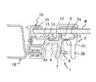
このスライド窓用ロック装置は、図2および図3に示すように、窓枠10側に形成されたロック受部11と、スライドガラスWに取り付けられて上記ロック受部11に係脱自在な掛止具1とからなっている。
【0009】
即ち、スライドガラスWは、キャビンや室内の壁面18に形成されてスライド方向に延びる窓枠10にガイドされて開閉自在となっている。
そして、窓枠10の開閉端にはストライカと呼ばれるロック受部11が設けられ、スライドガラスWに設けられた掛止具1の爪部3が前記ロック受部11に掛止られてロックされるようになっている。
ロック受部11は、図2に示すように、スライドガラスWを閉じる際にその先端を嵌合し隙間無く衝合させる窓枠10のチャンネル溝15に沿って室内側に固設されたストライカからなっており、先端は弧状に湾曲してガイド片12となっており、中途位置にはロック孔13が形成されており、爪部3が掛止可能となっている。
【0010】
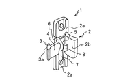
一方、掛止具1は、図1に示すように、スライドガラスWに固定される固定ベース部2と、前記ロック受部11に掛止可能な爪部3を有する引掛片部4と、引掛片部4を固定ベース部2に連接すると共に、引掛片部4をロック乃至ロック解除方向に屈曲させる支点P1(図2参照)を有する連設片部5と、前記引掛片部4から延びて先端がスライドガラスWに衝合して引掛片部4をロック姿勢に保持する保持片部6と、前記引掛片部4に連接して前記引掛片部4をロック乃至ロック解除姿勢に起伏させる操作片部7とからなって一体に形成されている。
ここで、掛止具1の素材としては、摩擦係数が小さく、耐クリープ性に優れ、弾性がある合成樹脂材が好ましく、例えばポリアミド(ナイロン)や、ポリアセタール等の高分子化合物が用いられるが、強度を高めるためにガラス繊維などを混入したものであってもよい。
【0011】
固定ベース部2は、両側にスライドガラスWに固定する取付片部2aを有し、中央には固定壁部2bを立設した構成からなっている。
この固定壁部2bの前方に、両側縁が取付片部2aから切り離されており、前記スライドガラスWから離間して中空位置に延びて引掛片部4につながる連設片部5が形成されている。
ここで連設片部5は、反発可能に撓むことができるように厚みがやや薄く設定されており、図2に示すように、引掛片部4のロック乃至ロック解除時の傾動に際してその屈曲支点P1となる。
【0012】
次ぎに、引掛片部4は前方へ延びると共に先端に掛止用の爪部3を有している。
爪部3は先端がやや内向きに傾斜する円弧状またはテーパ状のガイド面3aに形成されており、通常はロック姿勢に保持されている。
そこで、スライドガラスWを閉めると、爪部3のガイド面3aが前記ロック受部11の先端で固定位置にあるガイド片12と衝合し、爪部3のガイド面3aがガイド片12に沿って爪部3を押し上げ、ロック受部11の先端を通過させる。この際に、爪部3はロック方向に付勢されるので、ロック孔13に爪部3が整合すると爪部3が上記付勢力によりロック孔13に没入し、自動的にロックが行われる。
【0013】
ロック解除時には、操作片部7と固定壁部2bとに指を掛けわたし、反発力に抗して操作片部7を引き寄せ、引掛片部4を外向きに傾動させて爪部3をロック孔13から外す。
この際に、操作片部7の後方には、これと略直交して外方へ延びるストッパ8が設けられている。
操作片部7をロック解除方向に変位させた際に、爪部3がロック孔13から外れた位置でストッパ8の先端が固定壁部2bに衝合するように設定してあるので、引掛片部4はロック解除に必要なだけ傾倒し、支点となる連結片部5が必要以上に大きな角度で屈曲されることがなく、耐久性を向上させうる。
そして、これによりスライドガラスWは拘束から解除されるのでロックが外れ、適宜に窓を開けることができる。
また、操作片部7を離せば、引掛片部4は元の姿勢に戻る。
【0014】
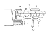
上記実施例では保持片部6を設けたが、この発明では保持片部6は設けなくてもよい。
図4に示す掛止具は、保持片部を設けない異なる実施例を示す。
この場合、連設片部5の厚みを厚くすることにより保持力を高めることができるが、支点として機能させるために支点個所に溝を形成する等して定位置で屈曲しやすくしてもよい。
これらの場合も前記実施例と同様の作用、効果を奏することができ、その他の構成は前記実施例と同様であるので、その説明を省略する。
【0015】
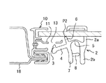
この発明で、保持片部6は、引掛片部4をスライドガラスWに対して略平行する姿勢に保持するためのものであるので、その先端はスライドガラスWに接するか、あるいは接近してしていればよい。
しかし、図1から図3に示した実施例においては、保持片部6の長さを、保持片部6の先端がスライドガラスWと接する長さよりも長く設定しており、連設片部5は僅かに撓んで取り付けられる。
【0016】
これにより、保持片部6の先端はスライドガラスWを加圧した状態でスライドガラスWに衝合しているので、引掛片部4の爪部3に与圧が働らく。
従って、操作片部7を操作する際に、はじめに軽く力を入れても引掛片部4は動かず、更に力を入れると動き始めるので、操作時の節度感を持たせることができる。
更に、爪部3がロック孔13にきつく掛止られている場合には、図3で示すように、操作片部7をロック解除方向に強く傾けると、保持片部6の先端が支点P2となり、逆に連設片部5は撓みを大きく膨らませながら引掛片部4をロック解除方向に傾動させて爪部3をロック孔13から外すことができる(図3参照)。
【0017】
図5に示すロック装置は、実願昭59−78016号に示されるような盗難防止用タイプとして考えられたスライド窓用ロック装置としても利用することができるようにした実施例である。
この場合、固定ベース部2に立設された摘み部2b'が固定壁部に対応しており、また摘みレバー部7が操作片部に対応する。
そして、摘みレバー部7を押し下げながら引掛片部4の爪部3をロック孔13から外すことができる。
その他の構成は前記実施例に準じるのでその説明を省略する。
【0018】
この実施例ではロック受部がロック孔からなる場合を例示したが、爪部に対応するフック状のロック受部であってもよい。
また、掛止具の素材は前記実施例に限定されるものではなく、適宜に選択した弾性を有する合成樹脂材を用いることができる。
その他、要するにこの発明の要旨を変更しない範囲で種々設計変更しうる。
【0019】
【発明の効果】
この発明では、従来二部品に分かれていた固定側の固定ベース部と、可動側の引掛片部や操作片部をバネ状部材となる連設片部で連結し、合成樹脂のような弾力性のある素材で一体に成型したので、部品点数や組立工数を減少させることができ、量産に適すると共にコストダウンを図ることができる。
また、保持片部の先端をスライドガラスとの衝合位置より長く設定することにより、前記連設部分を僅かに変形して取り付けることになり、操作時の節度感を持たせることができる。
更に、爪部がロック受部に強く係合している場合でも、保持片部の先端を支点とし、連設片部が撓んでしまっても、操作片部のより接近した梃作用で引掛片部を強く引き起こすことができ、容易にロック解除することができる。
【図面の簡単な説明】
【図1】この発明の掛止具の実施例を示す斜視図である。
【図2】ロック装置の作用を説明する側断面図である。
【図3】保持片部の先端を支点とした場合の作用を示す側断面図である。
【図4】保持片部を設けない場合の実施例を示す側断面図である。
【図5】異なる実施例を示す側断面図である。
【図6】従来の掛止具を示す斜視図である。
【符号の説明】
1 掛止具
2 固定ベース部
2a 取付片部
2b 固定壁部
3 爪部
3a ガイド面部
4 引掛片部
5 連設片部
6 保持片部
7 操作片部
8 ストッパ
10 窓枠
11 ロック受部
12 ガイド片
13 ロック孔
15 チャンネル溝
W スライドガラス[0001]
[Industrial application fields]
The present invention relates to an improvement of a lock device including a lock receiving portion formed on a window frame side and a latch attached to a slide glass and freely detachable from the lock receiving portion.
[0002]
[Prior art]
Conventionally, the following structure is known as a locking device for a sliding window that locks when an openable / closable sliding window that slides along a wall surface in the room or the like is closed.
That is, a fixed base with a bottom is fixed to the sliding window, and an operating member having a hook piece and an operating piece is pivotally attached to both side walls via a rotating shaft, and the operating member is a coil spring. The hook is biased in the locking direction, and a claw portion is formed at the tip of the hooking piece.
On the other hand, a window frame is provided on the wall surface side of the room, and a side edge of the sliding window is slidably held, and a receiving part that abuts on the tip of the sliding window is formed. The latch receiving piece protrudes.
When the sliding window is closed, the claw portion of the hooking piece gets over the hooking receiving piece and is locked to complete the locking.
When opening the sliding window, the operation piece is rotated by hand in the unlocking direction, the engagement between the claw portion and the latch receiving portion is released, and the sliding window may be moved in the opening direction.
However, in the conventional sliding window locking device as described above, it is necessary to separately provide a rotating shaft for pivotally attaching the operating member to the fixed member, which requires a large number of members, complicates assembly man-hours, and costs. There is a drawback.
Therefore, as shown in Japanese Utility Model Publication No. 7-18858, the applicant of the present invention is a slide in which a rotating shaft is provided integrally with an operating member and can be assembled by one-touch fitting into a bearing hole provided in a fixed base. A window locking device was proposed.
When this structure is shown in FIG. 6, the movable piece which has the
[0003]
[Problems to be solved by the invention]
However, in the sliding window locking device, the hooking piece is pivotally attached to the fixed base, and therefore there is a problem that assembly man-hours are generated.
Further, at the pivot attachment point, the pivot is rubbed by friction with the shaft lock receiving portion, and an abnormal noise is generated when the same material is used. For this reason, it is not possible to carry out the common take-up (set take-up) of both members, which is generally performed for reducing the investment in the mold.
In addition, if the pivot point has poor accuracy, the operation feeling may be deteriorated.
Furthermore, since the parts used are independent parts, it is necessary to form the parts so that they are not easily separated after assembly, which causes a problem that the structure becomes complicated and the cost of the mold increases.
[0004]
The present invention was devised in order to solve the above-mentioned problems. The main problem is that the hook piece and the fixed base, which have been conventionally divided into two parts, are integrally formed, and the hook piece is locked. Another object is to provide a sliding window locking device that can be bent in the unlocking direction.
Another object of the present invention is to provide a sliding window locking device provided with a holding piece so as to give an initial load to the hooking piece in order to give a sense of moderation during operation.
Still another object of the present invention is to provide a sliding window locking device that can tilt the hooking piece in the unlocking direction with the holding piece as a fulcrum even when the lock is tightly locked by the repulsive force of the seal. It is to provide.
[0005]
[Means for Solving the Problems]
In order to solve the above-mentioned problems, the present invention provides
In a lock device comprising a lock receiving portion formed on the window frame side, and a latch attached to the slide glass side and freely detachable from the lock receiving portion,
A locking base is fixed to the slide glass side, and a fixed base part;
A hooking piece having a claw that can be hooked to the lock receiving portion at the tip;
A connecting piece portion that is interposed between the hooking piece portion and the fixed base portion and extends along the slide glass, and that is a spring-like member having a portion that bends the hooking piece portion in the locking or unlocking direction;
An operation piece erected on the base end side of the hooking piece to displace the hooking piece in a locked or unlocked posture;
Projects outward behind the operation piece, and restricts the bending angle of the operation piece in the unlocking direction with the tip engaging the fixed wall or fixed base at the position where the claw is removed from the lock hole. The technical means of integrally forming the stopper formed in such a manner is taken.
[0006]
In the invention of
A technical means is provided in which the hook piece includes a holding piece that extends from the hook piece and has a tip that abuts the slide glass to hold the hook piece in a locked position.
Furthermore, in the invention of
Technical means is provided that the hooking piece can be tilted in the unlocking direction with the tip of the holding piece as a fulcrum by operation in the unlocking direction of the operating piece.
[0007]
In the invention of
The length of the holding piece is set to be longer than the length at which the tip of the holding piece is in contact with the slide glass, and a technical means is applied to apply pressure to the claw of the hook piece.
Furthermore, in the invention of
Technical means is provided on the rear side of the operation piece portion, which is provided with a stopper that abuts the fixed base portion at the completion position when the operation piece portion is displaced in the unlocking direction.
In the invention of
Technology that the material of the latch is made of polyamide (nylon) with a low coefficient of friction, excellent creep resistance, elasticity, polymer compounds such as polyacetal, or glass fiber mixed with it Take appropriate measures.
[0008]
DETAILED DESCRIPTION OF THE INVENTION
A preferred embodiment of the sliding window locking device of the present invention will be described below with reference to the drawings.
As shown in FIGS. 2 and 3, the sliding window locking device includes a
[0009]
That is, the slide glass W is freely opened and closed by being guided by the
A
As shown in FIG. 2, the
[0010]
On the other hand, as shown in FIG. 1, the latch 1 includes a fixed
Here, as the material of the latch 1, a synthetic resin material having a small coefficient of friction, excellent creep resistance, and elasticity is preferable. For example, a polymer compound such as polyamide (nylon) or polyacetal is used. Glass fibers or the like may be mixed to increase the strength.
[0011]
The fixed
In front of the fixed
Here, the connecting
[0012]
Next, the hooking
The
Therefore, when the slide glass W is closed, the
[0013]
When unlocking, put the finger on the
At this time, a
Upon displacing the
Then, the slide glass W is released from the restraint, so that the lock is released and the window can be opened appropriately.
Further, when the
[0014]
Although the holding
The latch shown in FIG. 4 shows a different embodiment in which no holding piece is provided.
In this case, the holding force can be increased by increasing the thickness of the
In these cases, the same operations and effects as those of the above-described embodiment can be obtained, and the other configurations are the same as those of the above-described embodiment, and thus the description thereof is omitted.
[0015]
In the present invention, the holding
However, in the embodiment shown in FIGS. 1 to 3, the length of the holding
[0016]
As a result, the tip of the holding
Therefore, when operating the
Further, when the
[0017]
The locking device shown in FIG. 5 is an embodiment that can be used as a sliding window locking device considered as a theft prevention type as shown in Japanese Utility Model Application No. 59-78016.
In this case, the
Then, the
Since other configurations are the same as those in the above embodiment, the description thereof is omitted.
[0018]
In this embodiment, the case where the lock receiving portion is formed of a lock hole is exemplified, but a hook-shaped lock receiving portion corresponding to the claw portion may be used.
Moreover, the material of the hook is not limited to the above-described embodiment, and a synthetic resin material having elasticity selected as appropriate can be used.
In addition, various design changes can be made without departing from the scope of the present invention.
[0019]
【The invention's effect】
In this invention, the fixed base portion on the fixed side, which has been divided into two parts in the past, and the hooking piece and operating piece on the movable side are connected by a continuous piece portion that becomes a spring-like member, and resilience like a synthetic resin. Since it is molded integrally with a certain material, the number of parts and the number of assembly steps can be reduced, which is suitable for mass production and cost reduction.
In addition, by setting the tip of the holding piece longer than the abutting position with the slide glass, the connecting portion is slightly deformed and attached, and a feeling of moderation during operation can be given.
Further, even when the claw portion is strongly engaged with the lock receiving portion, even if the connecting piece portion bends with the tip of the holding piece portion as a fulcrum, the hook piece is closer due to the closer action of the operation piece portion. The part can be caused strongly and can be easily unlocked.
[Brief description of the drawings]
FIG. 1 is a perspective view showing an embodiment of a latch according to the present invention.
FIG. 2 is a side sectional view for explaining the operation of the locking device.
FIG. 3 is a side sectional view showing the operation when the tip of the holding piece is a fulcrum.
FIG. 4 is a side sectional view showing an embodiment in the case where no holding piece is provided.
FIG. 5 is a side sectional view showing a different embodiment.
FIG. 6 is a perspective view showing a conventional latch.
[Explanation of symbols]
DESCRIPTION OF SYMBOLS 1
Claims (5)
掛止具が、スライドガラス側に固定される固定ベース部と、
前記ロック受部に掛止可能な爪部を先端に有する引掛片部と、
該引掛片部と固定ベース部との間に介設されてスライドガラスに沿って延びると共に、引掛片部をロック乃至ロック解除方向に屈曲させる部位を有するバネ状部材となる連設片部と、
前記引掛片部の基端側に立設されて引掛片部をロック乃至ロック解除姿勢に変位させる操作片部と、
該操作片部の後方で外方へ突出し、前記爪部がロック孔から外れた位置で先端が固定壁部または固定ベース部に衝合して操作片部のロック解除方向への屈曲角度を規制するように形成されたストッパとを一体に形成してなることを特徴とするスライド窓用ロック装置。In a lock device comprising a lock receiving portion formed on the window frame side, and a latch attached to the slide glass side and freely detachable from the lock receiving portion,
A locking base is fixed to the slide glass side, and a fixed base part;
A hooking piece having a claw that can be hooked to the lock receiving portion at the tip;
A connecting piece portion that is interposed between the hooking piece portion and the fixed base portion and extends along the slide glass, and that is a spring-like member having a portion that bends the hooking piece portion in the locking or unlocking direction;
An operation piece erected on the base end side of the hooking piece to displace the hooking piece in a locked or unlocked posture;
Projects outward behind the operation piece, and restricts the bending angle of the operation piece in the unlocking direction with the tip engaging the fixed wall or fixed base at the position where the claw is removed from the lock hole. A locking device for a sliding window, wherein the stopper is formed integrally with the stopper.
Priority Applications (1)
| Application Number | Priority Date | Filing Date | Title |
|---|---|---|---|
| JP05540299A JP3728131B2 (en) | 1999-03-03 | 1999-03-03 | Locking device for sliding window |
Applications Claiming Priority (1)
| Application Number | Priority Date | Filing Date | Title |
|---|---|---|---|
| JP05540299A JP3728131B2 (en) | 1999-03-03 | 1999-03-03 | Locking device for sliding window |
Publications (2)
| Publication Number | Publication Date |
|---|---|
| JP2000248803A JP2000248803A (en) | 2000-09-12 |
| JP3728131B2 true JP3728131B2 (en) | 2005-12-21 |
Family
ID=12997556
Family Applications (1)
| Application Number | Title | Priority Date | Filing Date |
|---|---|---|---|
| JP05540299A Expired - Fee Related JP3728131B2 (en) | 1999-03-03 | 1999-03-03 | Locking device for sliding window |
Country Status (1)
| Country | Link |
|---|---|
| JP (1) | JP3728131B2 (en) |
-
1999
- 1999-03-03 JP JP05540299A patent/JP3728131B2/en not_active Expired - Fee Related
Also Published As
| Publication number | Publication date |
|---|---|
| JP2000248803A (en) | 2000-09-12 |
Similar Documents
| Publication | Publication Date | Title |
|---|---|---|
| US6322126B1 (en) | Visor support apparatus | |
| US20040168487A1 (en) | Lid lock apparatus for glove box | |
| JPH05338496A (en) | Cover opening and closing device | |
| JP3728131B2 (en) | Locking device for sliding window | |
| JP4097115B2 (en) | Buckle for seat belt | |
| JP2001218340A (en) | Band clamp | |
| JPH09195608A (en) | Engagement structure | |
| JP3794466B2 (en) | Open / close lock device | |
| JP4698072B2 (en) | Clips, auto parts with clips, and rotating assist grips | |
| JP4091750B2 (en) | Side lock device for storage body | |
| JPH0571050U (en) | Vehicle storage device with damper function | |
| JPH0612145Y2 (en) | Open / closed door closed state holding device | |
| JP2001206078A (en) | Clip for fuel lid spring | |
| JP7406954B2 (en) | Installation device for vehicle interior parts | |
| JP3560172B2 (en) | Door opening and closing mechanism | |
| JPH1189778A (en) | Cleaning mop | |
| JP3568880B2 (en) | Lid opening and closing device | |
| JPH099462A (en) | Lock mechanism of holder | |
| JP3031443U (en) | Plastic door locking device | |
| JP3249472B2 (en) | Latch device | |
| KR0174658B1 (en) | Hair clip | |
| JP4116774B2 (en) | Stopper mounting structure for check link device | |
| JPH06305284A (en) | Binding | |
| JP3694632B2 (en) | Open / close lock device | |
| JP2537741Y2 (en) | Lock device |
Legal Events
| Date | Code | Title | Description |
|---|---|---|---|
| A977 | Report on retrieval |
Free format text: JAPANESE INTERMEDIATE CODE: A971007 Effective date: 20041001 |
|
| A131 | Notification of reasons for refusal |
Free format text: JAPANESE INTERMEDIATE CODE: A131 Effective date: 20041102 |
|
| A521 | Written amendment |
Free format text: JAPANESE INTERMEDIATE CODE: A523 Effective date: 20041228 |
|
| A131 | Notification of reasons for refusal |
Free format text: JAPANESE INTERMEDIATE CODE: A131 Effective date: 20050308 |
|
| A521 | Written amendment |
Free format text: JAPANESE INTERMEDIATE CODE: A523 Effective date: 20050509 |
|
| A131 | Notification of reasons for refusal |
Free format text: JAPANESE INTERMEDIATE CODE: A131 Effective date: 20050607 |
|
| A521 | Written amendment |
Free format text: JAPANESE INTERMEDIATE CODE: A523 Effective date: 20050801 |
|
| TRDD | Decision of grant or rejection written | ||
| A01 | Written decision to grant a patent or to grant a registration (utility model) |
Free format text: JAPANESE INTERMEDIATE CODE: A01 Effective date: 20050830 |
|
| A61 | First payment of annual fees (during grant procedure) |
Free format text: JAPANESE INTERMEDIATE CODE: A61 Effective date: 20050930 |
|
| R150 | Certificate of patent or registration of utility model |
Free format text: JAPANESE INTERMEDIATE CODE: R150 |
|
| FPAY | Renewal fee payment (event date is renewal date of database) |
Free format text: PAYMENT UNTIL: 20091007 Year of fee payment: 4 |
|
| S111 | Request for change of ownership or part of ownership |
Free format text: JAPANESE INTERMEDIATE CODE: R313117 |
|
| FPAY | Renewal fee payment (event date is renewal date of database) |
Free format text: PAYMENT UNTIL: 20121007 Year of fee payment: 7 |
|
| R350 | Written notification of registration of transfer |
Free format text: JAPANESE INTERMEDIATE CODE: R350 |
|
| FPAY | Renewal fee payment (event date is renewal date of database) |
Free format text: PAYMENT UNTIL: 20151007 Year of fee payment: 10 |
|
| R250 | Receipt of annual fees |
Free format text: JAPANESE INTERMEDIATE CODE: R250 |
|
| R250 | Receipt of annual fees |
Free format text: JAPANESE INTERMEDIATE CODE: R250 |
|
| LAPS | Cancellation because of no payment of annual fees |