JP3732550B2 - Water pressure valve - Google Patents
Water pressure valve Download PDFInfo
- Publication number
- JP3732550B2 JP3732550B2 JP11294895A JP11294895A JP3732550B2 JP 3732550 B2 JP3732550 B2 JP 3732550B2 JP 11294895 A JP11294895 A JP 11294895A JP 11294895 A JP11294895 A JP 11294895A JP 3732550 B2 JP3732550 B2 JP 3732550B2
- Authority
- JP
- Japan
- Prior art keywords
- valve
- chamber
- piston
- water
- open
- Prior art date
- Legal status (The legal status is an assumption and is not a legal conclusion. Google has not performed a legal analysis and makes no representation as to the accuracy of the status listed.)
- Expired - Fee Related
Links
Images
Landscapes
- Safety Valves (AREA)
Description
【0001】
【産業上の利用分野】
本発明は水圧バルブに関するものである。
【0002】
【従来の技術】
従来、ロールカー等の散水ホースを通じて夜中又は無人で散水している。
【0003】
【発明が解決しようとする課題】
従来ロールカー等の散水ホースを用いて散水しているが、使用中ホースが破損したとき、気付いてから元栓を止めていて元栓を止めるまで流れ放しである。そして夜間作業が気になるとき、元栓が止めてあるかどうか早朝確認する必要がある。
したがって、本発明は散水ホース等の破損又は接続金具の破損、外れ等のトラブルが生じても少量の水損失ですむ。又はオペレーターが安心して作業ができる水圧バルブをうることを目的とするものである。
【0004】
【課題を解決するための手段】
本発明は以上のような目的を達成するために次のような水圧バルブを提供するものである。すなわち、水路の上流側に開閉バルブを設けると共に、下流側にシリンダー室を設け、開閉レバーによって開閉する開閉バルブのロッドにシリンダー室のピストンを設け、かつ水路から空気チャンバーにつながる二叉分岐路を設け、分岐路の一方は空気チャンバー側に開くバルブを介して水路の上流側に連通し、他方の分岐路はピストンのシリンダー室に向かって開くバルブを介して下流側と連通する前記ピストンのシリンダー室に連通せしめ、下流側の減圧時開閉バルブが閉止側に向かって働くようにピストンを配置してなる水圧バルブである。
【0005】
【作用】
通常は、上流側水路室(A)、空気チャンバー室(B)、下流側水路室(C)、ピストン前方のシリンダー室(D)とも同等の水圧がかかっていて、ホース先端をあけることにより、水は主流通水路(20)の上流側水路室(A)から開閉バルブ(1)を通り、主流通水路(22)の下流側水路室(C)に流れる。 この時センサー圧は上流側水路室(A)から分岐路(5)のバルブ(2)を通り、空気チャンバー(B)内に入り、空気チャンバー(B)内の空気を圧縮し、分岐路(6)のバルブ(3)を通り、ピストン前方のシリンダー室(D)に圧力がかかっている。
トラブルが生じたら下流側の水路室(C)の圧力が急に下り、空気チャンバー(B)内の圧縮された空気は一気にバルブ(2)(3)に流れるが、バルブ(2)は閉まるようになっているので一方のバルブ(3)が開き、ピストン前方のシリンダー室(D)に流れ、ピストン(10)を右方に動かし、これによって開閉バルブ(1)が閉じ、水の流れを止める。
【0006】
【実施例】
以下図面に示す実施例について説明する。
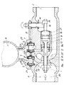
(A)は主流通水路(20)の上流側水路室、(B)は空気チャンバー、(C)は主流通水路(22)の下流側水路室、(D)はピストン前方のシリンダー室である。
(1)は主流通水路を開閉するバルブで弁座(19)との間にスプリング(12)がそのロッド(8)に捲装されており、弁座口(19a)を開く方向に付勢されている。
水路(5)は主通水路(20)より分岐して、空気チャンバー(B)につながり、その分岐路(5)に空気チャンバー(B)側に開くバルブ(2)があり、バネ(4)で常時水路口(5a)を閉止するようになっている。図示のものはシール材(21)(21)でバルブ(2)のシール性をよくしている。
又、空気チャンバー(B)につながる他方の分岐路(6)の水路口(6a)にピストン(10)前方のシリンダー室(D)に向かって開くバルブ(3)があり、バネ(7)で常時水路口(6a)を閉じるようになっていて、弁座のシール材(23)でシール性をよくしている。
(11)は下流側に設けられたシリンダー室であって、下流側の水路室(C)に連通しているシリンダー室(11)にはピストン(10)があり、開閉バルブ(1)のロッド(8)にスライド自在に設けられている。そのスライドストロークはロッド端の鍔板(9)とリング(9a)との間である。
そして前記した分岐路(6)はピストン前方のシリンダー室(D)に連通している。
【0007】
(13)は水路壁に設けられた開閉レバーで、ロッド(14)とリンク(15)を介してロッド(16)を動かし、ロッド(16)のリング(17)で栓(18)を前後動させ、栓(18)でピストン鍔板(9)を動かすようになっている。
したがって、開閉レバー(13)でピストンロッド(8)を動かし、開閉バルブ(1)を開くことができる。
なお、シリンダー室(11)は栓(18)で下流側の水路室(C)と遮断されないようになっている。
以上のような水圧バルブ装置は水路のできるだけ元栓に近いところに設置する。そして開閉バルブ(1)の開閉は手動で行う。
通常は上流側水路室(A)、空気チャンバー室(B)、下流側水路室(C)、ピストン前方の水路室(D)は同等の水圧がかかっていて開閉レバー(13)でホース先端をあけると水は主流通水路(20)の上流側水路室(A)から開閉バルブ(1)を経て、主流通水路(22)の下流側水路室(C)に流れる。
このとき、センサー圧は上流側水路室(A)からバルブ(2)を通り、空気チャンバー(B)内に入り、空気チャンバー(B)内の空気を圧縮し、バルブ(3)を通ってピストン前方のシリンダー室(D)に圧力がかかっており、上流側水路室(A)、空気チャンバー(B)、下流側水路室(C)、ピストン前方のシリンダー室(D)とも同等の水圧がかかっているので、ピストン(10)はリング(9a)で止まる位置にある。
トラブルが生じると、下流側室(C)の圧力が急に下り、空気チャンバー(B)内に圧縮されていた空気が一気にバルブ(2)(3)に向かって流れるが、バルブ(2)は水路口(5a)を閉じることとなるので、バルブ(3)が開き、ピストン前方のシリンダー室(D)に流れ、ピストン(10)を右方に動かし、ピストン(10)が鍔板(9)に当るとロッド(8)によって開閉バルブ(1)が閉じる方向に動く。したがって開閉バルブ(1)が閉じて水の流れを止める。
したがって水の流れ放しはなく、少量の水損失で済むし、オペレーターは常時注意する必要なく、安心して作業ができる。
【0008】
本発明は以上の如く、主流通水路に分岐路を設けて、これを空気チャンバーに連通するようにし、分岐路の一方は空気チャンバー側に開くバルブを介して水路の上流側と空気チャンバーに連結し、他方の分岐路はピストン前方のシリンダー室側に開くバルブを介してシリンダー室に連通するようにしてセンサー圧の水路を形成し、トラブルによって下流側水路室の水圧が下がることによって分岐路のセンサー圧と水路圧との間に差ができ、これによってピストンを作用させて開閉バルブを閉じるようにしたものである。
【0009】
【発明の効果】
本発明によれば、散水ホース等の破損又は接続金具の破損、外れ等のトラブルが発生しても少量の水損失で済むのでオペレーターは安心できる。
【図面の簡単な説明】
【図1】本発明水圧バルブの切断面図
【符号の説明】
A 上流側水路室
B 空気チャンバー
C 下流側水路室
D ピストン室
1 開閉バルブ
2 バルブ
3 バルブ
4 バネ
5 分岐路
6 分岐路
7 バネ
8 ロッド
9 鍔板
10 ピストン
11 シリンダー
12 バネ
13 開閉レバー
14 ロッド
15 リンク
16 ロッド
17 リング
18 栓
19 弁座
20 主流通水路
21 シール材
22 主流通水路
23 シール材[0001]
[Industrial application fields]
The present invention relates to a hydraulic valve.
[0002]
[Prior art]
Conventionally, water is sprayed at night or unattended through a watering hose such as a roll car.
[0003]
[Problems to be solved by the invention]
Conventionally, water is sprayed using a watering hose such as a roll car, but when the hose is broken during use, the main plug is stopped after it is noticed, and it is allowed to flow until the main plug is stopped. And when you are worried about working at night, you need to check early in the morning to see if the main plug is turned off.
Therefore, the present invention requires a small amount of water loss even if trouble such as damage to the watering hose or the like, damage to the connection fitting, or disconnection occurs. Or it aims at obtaining the hydraulic valve which an operator can work in comfort.
[0004]
[Means for Solving the Problems]
In order to achieve the above object, the present invention provides the following hydraulic valve. In other words, an open / close valve is provided upstream of the water channel, a cylinder chamber is provided downstream, a piston of the cylinder chamber is provided on the rod of the open / close valve that is opened and closed by the open / close lever , and a bifurcated branch passage that connects the water channel to the air chamber is provided. One of the branch passages communicates with the upstream side of the water passage through a valve that opens to the air chamber side, and the other branch passage communicates with the downstream side through a valve that opens toward the cylinder chamber of the piston. This is a hydraulic valve that is connected to the chamber and has a piston arranged so that the on-off valve at the time of pressure reduction on the downstream side works toward the closing side.
[0005]
[Action]
Normally, the upstream water channel chamber (A), the air chamber chamber (B), the downstream water channel chamber (C), and the cylinder chamber (D) in front of the piston are under the same water pressure. Water flows from the upstream water channel chamber (A) of the main flow channel (20) through the open / close valve (1) to the downstream water channel chamber (C) of the main flow channel (22). At this time, the sensor pressure passes from the upstream water channel chamber (A) through the valve (2) of the branch channel (5), enters the air chamber (B), compresses the air in the air chamber (B), Pressure is applied to the cylinder chamber (D) in front of the piston through the valve (3) of 6).
When trouble occurs, the pressure in the downstream water channel chamber (C) suddenly drops, and the compressed air in the air chamber (B) flows to the valves (2) and (3) all at once, but the valve (2) seems to be closed. Therefore, one valve (3) opens, flows into the cylinder chamber (D) in front of the piston, moves the piston (10) to the right, thereby closing the on-off valve (1) and stopping the flow of water. .
[0006]
【Example】
Embodiments shown in the drawings will be described below.
(A) is an upstream water channel chamber of the main flow channel (20), (B) is an air chamber, (C) is a downstream water channel chamber of the main flow channel (22), and (D) is a cylinder chamber in front of the piston. .
(1) is a valve that opens and closes the main flow channel, and a spring (12) is mounted on the rod (8) between the valve seat (19) and urges the valve seat port (19a) to open. Has been.
The water channel (5) branches from the main water channel (20) and is connected to the air chamber (B). The branch channel (5) has a valve (2) that opens to the air chamber (B) side, and the spring (4). Thus, the waterway mouth (5a) is always closed. The illustrated one is a sealing material (21) (21) that improves the sealing performance of the valve (2).
In addition, there is a valve (3) that opens toward the cylinder chamber (D) in front of the piston (10) at the water passage opening (6a) of the other branch passage (6) connected to the air chamber (B). The water channel opening (6a) is always closed, and the sealing performance of the valve seat sealing material (23) is improved.
(11) is a cylinder chamber provided on the downstream side, the cylinder chamber (11) communicating with the downstream water channel chamber (C) has a piston (10), and a rod of the on-off valve (1) (8) is slidably provided. The slide stroke is between the rod end plate (9) and the ring (9a).
The branch passage (6) communicates with the cylinder chamber (D) in front of the piston.
[0007]
(13) is an opening / closing lever provided on the water channel wall, which moves the rod (16) via the rod (14) and the link (15), and moves the plug (18) back and forth by the ring (17) of the rod (16). The piston plate (9) is moved by the stopper (18).
Therefore, the piston rod (8) can be moved by the open / close lever (13) to open the open / close valve (1).
The cylinder chamber (11) is not blocked from the downstream water channel chamber (C) by the stopper (18).
The water pressure valve device as described above is installed as close to the main plug as possible in the water channel. The opening / closing valve (1) is manually opened and closed.
Normally, the upstream water channel chamber (A), the air chamber chamber (B), the downstream water channel chamber (C), and the water channel chamber (D) in front of the piston are under the same water pressure. When opened, water flows from the upstream water channel chamber (A) of the main flow channel (20) through the open / close valve (1) to the downstream water channel chamber (C) of the main flow channel (22).
At this time, the sensor pressure passes from the upstream water passage chamber (A) through the valve (2), enters the air chamber (B), compresses the air in the air chamber (B), passes through the valve (3), and the piston. Pressure is applied to the front cylinder chamber (D), and the same water pressure is applied to the upstream water channel chamber (A), air chamber (B), downstream water channel chamber (C), and cylinder chamber (D) in front of the piston. Therefore, the piston (10) is in a position where it stops at the ring (9a).
When trouble occurs, the pressure in the downstream chamber (C) suddenly drops, and the air compressed in the air chamber (B) flows toward the valves (2) and (3) all at once, but the valve (2) is water. Since the passageway (5a) is closed, the valve (3) opens, flows into the cylinder chamber (D) in front of the piston, moves the piston (10) to the right, and the piston (10) moves to the saddle plate (9). When it hits, the open / close valve (1) is moved in the closing direction by the rod (8). Therefore, the on-off valve (1) is closed to stop the flow of water.
Therefore, there is no flow of water, a small amount of water is lost, and the operator does not need to be careful at all times and can work with peace of mind.
[0008]
As described above, according to the present invention, a branch channel is provided in the main circulation channel and communicates with the air chamber, and one of the branch channels is connected to the upstream side of the channel and the air chamber via a valve that opens to the air chamber side. The other branch passage is connected to the cylinder chamber through a valve that opens to the cylinder chamber side in front of the piston to form a sensor pressure water passage, and the water pressure in the downstream water passage chamber decreases due to a trouble. There is a difference between the sensor pressure and the water channel pressure, which causes the piston to act and close the open / close valve.
[0009]
【The invention's effect】
According to the present invention, even if trouble such as breakage of the watering hose or the like, breakage or disconnection of the connection fitting occurs, a small amount of water loss is sufficient, so that the operator can be relieved.
[Brief description of the drawings]
FIG. 1 is a sectional view of a hydraulic valve according to the present invention.
A upstream water channel chamber B air chamber C downstream water channel chamber D piston chamber 1 open / close valve 2 valve 3 valve 4 spring 5 branch channel 6 branch channel 7
10 piston
11 cylinders
12 Spring
13 Open / close lever
14 Rod
15 links
16 rod
17 rings
18 stoppers
19 Valve seat
20 Main distribution channel
21 Sealing material
22 Main distribution channel
23 Sealing material
Claims (1)
Priority Applications (1)
| Application Number | Priority Date | Filing Date | Title |
|---|---|---|---|
| JP11294895A JP3732550B2 (en) | 1995-05-11 | 1995-05-11 | Water pressure valve |
Applications Claiming Priority (1)
| Application Number | Priority Date | Filing Date | Title |
|---|---|---|---|
| JP11294895A JP3732550B2 (en) | 1995-05-11 | 1995-05-11 | Water pressure valve |
Publications (2)
| Publication Number | Publication Date |
|---|---|
| JPH08303625A JPH08303625A (en) | 1996-11-22 |
| JP3732550B2 true JP3732550B2 (en) | 2006-01-05 |
Family
ID=14599535
Family Applications (1)
| Application Number | Title | Priority Date | Filing Date |
|---|---|---|---|
| JP11294895A Expired - Fee Related JP3732550B2 (en) | 1995-05-11 | 1995-05-11 | Water pressure valve |
Country Status (1)
| Country | Link |
|---|---|
| JP (1) | JP3732550B2 (en) |
-
1995
- 1995-05-11 JP JP11294895A patent/JP3732550B2/en not_active Expired - Fee Related
Also Published As
| Publication number | Publication date |
|---|---|
| JPH08303625A (en) | 1996-11-22 |
Similar Documents
| Publication | Publication Date | Title |
|---|---|---|
| US4010770A (en) | Velocity flow control valve for fluid line | |
| JPH02286976A (en) | Pressure-operated type check valve | |
| JPH02266172A (en) | Fluid switching device and faucet assembly | |
| CA2336265A1 (en) | Bidirectional check valve for hydraulic system | |
| US4706548A (en) | Two-hand safety control mechanism | |
| US4145026A (en) | Valve with self-actuating fluid seal | |
| KR950009017A (en) | Gas spring with filling valve | |
| GB2185299A (en) | Hydraulic servo brake system with slip control | |
| JP3732550B2 (en) | Water pressure valve | |
| CA1057343A (en) | Shutoff and exhaust valve for air brakes | |
| GB1387892A (en) | Multi-circuit protective valve assembly | |
| FR2598482A1 (en) | SAFETY VALVE | |
| WO2023072695A1 (en) | Hydraulic fitting | |
| JPH05253314A (en) | Opening/closing valve for fire extinguishing equipment | |
| DE2453466C2 (en) | Pressure ratio valve | |
| FR2426201A1 (en) | VALVE ARRANGEMENT AVOIDING WATER BREAKS | |
| US5284384A (en) | Spring brake valve | |
| CA1054187A (en) | Fluid brake control system | |
| US3523553A (en) | Motor operated fluid valve | |
| US2832646A (en) | Emergency relay valve for tractor trailer brake system | |
| US5507466A (en) | Volumetric hydraulic fuse valve | |
| CS261248B2 (en) | Change-over valve for hydraulic waliking support | |
| SU1174654A1 (en) | Safety device | |
| US1793600A (en) | Angle-cock device | |
| SU857615A1 (en) | Pneumatic valve |
Legal Events
| Date | Code | Title | Description |
|---|---|---|---|
| A131 | Notification of reasons for refusal |
Free format text: JAPANESE INTERMEDIATE CODE: A131 Effective date: 20050322 |
|
| A521 | Written amendment |
Free format text: JAPANESE INTERMEDIATE CODE: A523 Effective date: 20050520 |
|
| TRDD | Decision of grant or rejection written | ||
| A01 | Written decision to grant a patent or to grant a registration (utility model) |
Free format text: JAPANESE INTERMEDIATE CODE: A01 Effective date: 20051011 |
|
| A61 | First payment of annual fees (during grant procedure) |
Free format text: JAPANESE INTERMEDIATE CODE: A61 Effective date: 20051013 |
|
| R150 | Certificate of patent or registration of utility model |
Free format text: JAPANESE INTERMEDIATE CODE: R150 |
|
| FPAY | Renewal fee payment (event date is renewal date of database) |
Free format text: PAYMENT UNTIL: 20081021 Year of fee payment: 3 |
|
| FPAY | Renewal fee payment (event date is renewal date of database) |
Free format text: PAYMENT UNTIL: 20091021 Year of fee payment: 4 |
|
| FPAY | Renewal fee payment (event date is renewal date of database) |
Free format text: PAYMENT UNTIL: 20091021 Year of fee payment: 4 |
|
| FPAY | Renewal fee payment (event date is renewal date of database) |
Free format text: PAYMENT UNTIL: 20101021 Year of fee payment: 5 |
|
| LAPS | Cancellation because of no payment of annual fees |