JP3734367B2 - Quartz glass tube cutting method and apparatus - Google Patents
Quartz glass tube cutting method and apparatus Download PDFInfo
- Publication number
- JP3734367B2 JP3734367B2 JP15127298A JP15127298A JP3734367B2 JP 3734367 B2 JP3734367 B2 JP 3734367B2 JP 15127298 A JP15127298 A JP 15127298A JP 15127298 A JP15127298 A JP 15127298A JP 3734367 B2 JP3734367 B2 JP 3734367B2
- Authority
- JP
- Japan
- Prior art keywords
- glass tube
- quartz glass
- cutting
- cutter blade
- pressing
- Prior art date
- Legal status (The legal status is an assumption and is not a legal conclusion. Google has not performed a legal analysis and makes no representation as to the accuracy of the status listed.)
- Expired - Lifetime
Links
- VYPSYNLAJGMNEJ-UHFFFAOYSA-N Silicium dioxide Chemical compound O=[Si]=O VYPSYNLAJGMNEJ-UHFFFAOYSA-N 0.000 title claims description 147
- 238000005520 cutting process Methods 0.000 title claims description 100
- 238000000034 method Methods 0.000 title claims description 13
- 239000011521 glass Substances 0.000 claims description 39
- 238000010586 diagram Methods 0.000 description 6
- 239000010432 diamond Substances 0.000 description 5
- 229910003460 diamond Inorganic materials 0.000 description 5
- 230000002093 peripheral effect Effects 0.000 description 5
- 230000001105 regulatory effect Effects 0.000 description 2
- XAGFODPZIPBFFR-UHFFFAOYSA-N aluminium Chemical compound [Al] XAGFODPZIPBFFR-UHFFFAOYSA-N 0.000 description 1
- 229910052782 aluminium Inorganic materials 0.000 description 1
- 238000013459 approach Methods 0.000 description 1
- 238000005452 bending Methods 0.000 description 1
- 238000001514 detection method Methods 0.000 description 1
- 238000006073 displacement reaction Methods 0.000 description 1
- 230000000694 effects Effects 0.000 description 1
- 238000007496 glass forming Methods 0.000 description 1
- 239000000463 material Substances 0.000 description 1
- 238000007790 scraping Methods 0.000 description 1
Images




Classifications
-
- C—CHEMISTRY; METALLURGY
- C03—GLASS; MINERAL OR SLAG WOOL
- C03B—MANUFACTURE, SHAPING, OR SUPPLEMENTARY PROCESSES
- C03B33/00—Severing cooled glass
- C03B33/06—Cutting or splitting glass tubes, rods, or hollow products
Landscapes
- Chemical & Material Sciences (AREA)
- Engineering & Computer Science (AREA)
- Materials Engineering (AREA)
- Organic Chemistry (AREA)
- Re-Forming, After-Treatment, Cutting And Transporting Of Glass Products (AREA)
Description
【0001】
【発明の属する技術分野】
本発明は石英ガラス管をカッターにより切断する石英ガラス管の切断方法及び装置に関する。
【0002】
【従来の技術】
従来より、石英ガラス管を切断する場合は、石英ガラス管をその外周方向に回転させた状態でダイヤモンドブレードを降下させて行う。
この際に、図8(a)に示すように石英ガラス管載置台106のガラス管回転用ローラ103に石英ガラス管105を載置して、自動で前記外周方向に回転して前記ブレード102を降下させると、石英ガラス管の載置場所である前記ローラ103及び石英ガラス管105の外周面の曲がり等により石英ガラス管105が長手方向にずれて、図8(b)に示すように前記外周面上の切断開始位置と切断終了位置とが一致せず段差を生じてしまう。
【0003】
【発明が解決しようとする課題】
かかる欠点を解消するために、作業者により石英ガラス管長手方向の前記ずれを防止しつつ切断するには作業者に負担を強いることとなり、作業時間が掛かり、コストアップとなる。
【0004】
また、前記ずれを防止するために、石英ガラス管をチャックによって保持する保持機構を設けるとともに、保持状態で石英ガラス管の外周方向に石英ガラス管を回転させる回転機構を設けることが考えられるが、大径の石英ガラス管を前記チャックに保持する作業に時間が費やされ、切断作業効率が低下し、コストアップとなる。
【0005】
本発明はかかる従来の欠点に鑑み、作業者に負担を強いることがない石英ガラス管切断方法及び装置を提供することを目的とするものである。
【0006】
【課題を解決するための手段】
本発明は、カッターブレードの切断刃部を石英ガラス管外周に押圧して切断する石英ガラス管の切断方法において、
前記石英ガラス管をガラス管載置台に載置した状態で石英ガラス管の外周を押圧保持する押圧保持ステップと、
前記石英ガラス管を切削基準位置に停止させた状態でカッターブレードにより石英ガラス管の切断を開始し、所定深さまで切削する第1の切削ステップと、
所定深さまで切削後、前記石英ガラス管を一周回転して、ガラス管全周にわたって切削して、石英ガラス管全周を切断する第2の切断ステップと、
前記第2の切断ステップで生じた段差を除去するために、石英ガラス管が1回転したことをセンサが検出した後、石英ガラス管の押圧力を解除した状態で前記カッターブレード側面側に向け該石英ガラス管をガラス管長手方向に押圧するようにしながら石英ガラス管の2周目の回転を行い、前記カッターブレードの側面に石英ガラス管端面を押圧させながら前記段差が生じた切断面を平坦化することを特徴とする石英ガラス管の切断方法である。
更に本発明は、請求項1記載の石英ガラス管の切断方法に用いる装置において、
前記石英ガラス管を載置した状態で前記石英ガラス管の外周方向に回転可能な石英ガラス管載置台と、
前記石英ガラス管の長さ方向と交差する方向に前記カッターを往復動可能に配置したカッターブレードと、
石英ガラス管をガラス管載置台に載置した状態で石英ガラス管の外周を押圧保持する押圧保持手段と、
石英ガラス管を切削基準位置に停止させる基準位置検知手段と、
カッターブレードにより石英ガラス管の切断を開始し、所定深さまで切削する所定深さを検知する手段と、
所定深さまで切削後、前記石英ガラス管を回転させる手段と
前記石英ガラス管切断時に位置するカッターブレード側面側に向け該石英ガラス管をガラス管長手方向に押圧させる手段とにより構成するのがよく、例えば前記石英ガラス管をガラス管長手方向に押圧させる手段が、載置台2をカッターブレード直下より石英ガラス管を上向きに傾斜させる手段であるのがよく、又前記カッターブレードは、石英ガラス管全周切断で生じた段差を、前記カッターブレードの側面により研削除去できるダイヤモンドカッターブレードであるのがよく、又石英ガラス管をガラス管載置台に載置した状態で石英ガラス管の外周を押圧保持する押圧保持手段が、ガラス管押さえベルトであるのがよい。
【0007】
ここにおいて、石英ガラス管は外周方向に回転しているので、カッターブレードは切断刃部が石英ガラス管と食い込む回転方向において切断することができる。
【0008】
そして、前記カッターブレードの切断刃部を前記ガラス管の外周より所定深さ、すなわち、前記切断刃部の切削域が石英ガラス管の周面を形成する石英ガラスの厚さ分を完全にカバーするように切断降下させればよく、このために円盤状のブレードを用いた場合においても、ブレード外径を大きくとる必要はなく、大径のブレードを必要としないのでブレードの欠けなどに対する耐久性がよい。
【0009】
また、カッターブレード部の切断刃部の片面に前記ガラス管の切断面から負荷が押圧されるので、切断中に長手方向に石英ガラス管が振動して切断寸法がバラツク恐れが少ない。
【0010】
また、前記石英ガラス管載置台に前記切断刃部の片面に向かって前記ガラス管の自重による負荷が押圧されるように前記ガラス管が載置されるように構成することも本発明の有効な手段である。かかる押圧保持手段は、石英ガラス管を傾斜することにより簡単に構成することができる。
【0011】
また、前記押圧保持は、常時押圧保持する必要はなく、カッターブレードの切断刃部が石英ガラス管の外周と接触する時期に同期して行われてもよい。
よって、少なくとも、切断状態において前記石英ガラス管載置台に前記カッターブレードの切断刃部の片面に向かって前記ガラス管が押圧されるように載置することも本発明の有効な手段である。かかる押圧保持手段は、前記ガラス管の外周と当接して前記ガラス管の長さ方向に接触回転する回転ローラにより構成することができる。
【0012】
また、この場合に前記第2の切断ステップで生じた段差を除去するために、石英ガラス管の押圧力を解除した状態で前記段差を研削する段差除去ステップを有するのがよく、例えば前記段差除去ステップが2周目の回転で前記カッターブレードの側面を利用して切断面を平坦化するのがよい。
この平坦化の際には、前記切断刃部の片面に前記ガラス管の切断面から負荷が押圧されるので、前記切断刃部の片面に別途ガラス管を介して押圧力を付与する必要はなく、作業者の負担が軽減される。
【0013】
また、かかる石英ガラス管の押圧力を解除した状態で前記段差を研削する段差除去ステップは、前記切断刃部の片面に前記ガラス管の切断面から負荷が押圧されるので、切断終了後連続して自動的に行うことができ作業者の負担が軽減される。
【0014】
【発明の実施の形態】
以下、本発明を図に示した実施の形態を用いて詳細に説明する。但し、この実施の形態に記載される構成部品の寸法、材質、形状、その相対配置などは特に特定的な記載が無い限り、この発明の範囲をそれのみに限定する趣旨ではなく単なる説明例に過ぎない。
【0015】
先ず、本実施の形態に用いる石英ガラス管切断装置の概略を説明する。
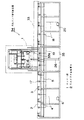
図1は、石英ガラス管切断装置の概略を示す一実施形態図、図2は、図1のカッター部を示す平面図、図3は、図2の要部を示す側面図、図4は、本実施の形態に用いる石英ガラス管切断装置の制御装置の概略を示す一実施形態図である。
【0016】
本石英ガラス管切断装置34は、石英ガラス管33を長手方向に摺動可能に載置する石英ガラス管載置台2を上部に配置した基台35と、該載置台2の中央部上方に配置され、内部に上下動可能なダイヤモンドカッターブレード16を内蔵したカッター部1とで構成される。
【0017】
前記載置台2は、長手方向に断面V溝2a(図3(a))が形成され、該V溝面に沿って該面上より若干突出したローラ面を有する4個のガラス管回転用ローラ3が、長手方向に多数配置されている。
該ローラ3は基台35内に配置されたローラ回転用モータ6によりチェーン4を介して回転駆動力が伝達される。
尚、このローラ3は図示しないリンク機構で石英ガラス管33を載置する上止位置とその下方の退避位置間を上下動可能に構成してもよい。このように構成し、ローラ3が退避位置にして石英ガラス管を載置台2上に載置することにより石英ガラス管を載置する際に誤って前記ローラ上に落下しても前記ローラ3に衝撃が加わることがない。
【0018】
また、基台35内には前記ローラ3と直交方向にローラ17が配置され、該ローラ17はモータ20によってチェーン18を介して回転駆動力が伝達するように構成されるとともに、図示しないリンク機構で前記ローラ3より高い位置で石英ガラス管33を長手方向に摺動可能に載置する上止位置とその下方の退避位置間を上下動可能に構成されている。
【0019】
尚、前記載置台2はカッターブレード16直下よりは図1上左右両端側が若干高めに形成されているので、載置台中央側に石英ガラス管の自重より押圧力が付与される。そして、その傾斜は石英ガラス管の大きさ、すなわち質量により相違するが3mに対して1〜3mmの傾斜度が望ましい。
また、前記ローラ17は前記上止位置と退避位置との間に前記ローラ3と同じ位置で石英ガラス管33の外周と接触して停止させ、該石英ガラス管33を長手方向に押圧するように構成することも可能である。この場合には載置台2を傾斜させなくともよい。
【0020】
次に、カッター部1を説明する。図2及び3において、基台35の上部には断面コ字状の切断部フレーム21が補助台37を介して立設され、該フレーム21には中央上部に開口部21aが開設され、該開口部21a内にはプーリ36が回転可能に配置され、フレーム21の前面にはガイドレール23、23が設けられ、該ガイドレール23、23上を上下摺動可能に摺動板28が配設されている。該摺動板28の下側は、エアシリンダ26(図1)の摺動軸26aに連結している。
【0021】
摺動板28は前記開口部21aに対応して中央上部が長孔状に開口部28aが形成され、該開口部28aの縁部28bにはベルト29の一端が固着され、該ベルト29は前記プーリ36に支持されて、その他端にはバランサ27が吊り下げられている。
【0022】
摺動板28には断面コ字状のカッター部フレーム20が配設され、該フレーム20には棚板20b,20cが設けられ、該棚板20bには後述する基準ローラ部フレーム13の位置決めをするエアシリンダ7、前記フレーム13を摺動するモータ9、及び後述するカッターブレード16を回転するモータ8が配設されている。
棚板20cには、前記モータ8からベルト30により回転可能にダイヤモンドカッターブレード16が配置されている。
【0023】
また、フレーム20にはガイドレール24、24が配設され、該ガイドレール24、24上を上下摺動可能に基準ローラ部フレーム13が配設されている。
該フレーム13には前記モータ9の回転軸9aの雄ネジ部9bと螺合する雌ネジ部13aが設けられている。また、フレーム13の図2上左右端には突出片13b,13bが設けられ、該突出片には腕部13c,13cが配設され、該腕部13c、13cには基準ローラ14、14及び、該ローラ14の近傍にはガラス管回転位置検出センサ15、15が配設されている。
【0024】
切断部フレーム21の図2上左右両端側には、図3(b)に示すように、ガイドレール25、25が配設され、該ガイドレール25、25上を上下摺動可能にガラス管押さえベルト部10、10が配設されている。該ベルト部10には、エアシリンダ11が固着され、該シリンダ11の駆動軸11aの先端は補助台37に固着されている。
【0025】
前記ベルト部10には、一対のローラ取付板32、32が所定距離離間して2個配設され、該一対のローラ取付板32にはそれぞれローラ31、31が回転可能に設けられ、該ローラ31、31にはガラス管押さえベルト12が回動可能に懸架されている。
【0026】
図4は石英ガラス管切断装置の機構部分と電気制御部分との配線状態を示す概略構成図である。
コンピュータ38は、図示しないキーボードによる入出力装置が接続されるとともに、I/O拡張BOX39、パルスボード40、I/Oボード41を介してインターフェースBOX46と接続され、DAボード42を介してインバータ43に接続されている。
【0027】
インターフェースBOX46に接続されているエアー用電磁バルブ47は、石英ガラス管33を上方から押さえるガラス管押さえベルト12を有するガラス管押さえベルト部10を摺動するエアシリンダ11と、エアシリンダ7と、カッターブレード16を石英ガラス管33に接近離間するエアシリンダ26に接続され、これらを制御する。
【0028】
インターフェースBOX46に接続されているドライバ45はカッターブレード16の切り込み深さを制御するモータ9に接続されている。
また、インターフェースBOX46に接続されているドライバ44は石英ガラス管33を周方向に回転するモータ6に接続されている。
DAボード42に接続されるインバータ43はカッターブレード16を回転するモータ8に接続されている。
そして、石英ガラス管33の周方向回転位置を検出するセンサ15、及び基準ローラ14が石英ガラス管33を検出したときに出力を生じる図示しないスイッチセンサはインターフェースBOX46に接続されている。
【0029】
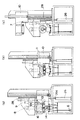
次に、図1、図5〜図7を用いて、本実施の形態の動作をステップ別に説明する。
ステップ(1):石英ガラス管33は、図1に示すように載置台2の右側に載置し、外周に切断開始場所を示す指標33aとしてアルミのテープを貼着する。
ステップ(2):コンピュータ38の入出力装置を操作してエアシリンダ11を動作させ、ガラス管押さえベルト部10を図5に示す実線の位置から一点鎖線10′のごとく降下させ、ガラス管押さえベルト12により石英ガラス管33の外周を押圧保持する。
【0030】
ステップ(3):コンピュータ38の入出力装置を操作して自動切断モードを立ち上げると、エアシリンダ26が動作し、摺動板28が図5の上止位置から降下を始め、摺動板28に設けられているカッター部フレーム20及び基準ローラ部フレーム13が降下する。
【0031】
ステップ(4):基準ローラ14が石英ガラス管33の外周に当接すると基準ローラ14の取付部分が撓み、図示しないスイッチが閉成し、センサ15(図2)が切断開始場所を示す指標33aを検出していないことを条件にモータ6が回転してローラ3が回転し、石英ガラス管33が矢印方向に回転し、前記指標33aをセンサ15が検出して、石英ガラス管33の回転が停止する(図6(a))。
【0032】
ステップ(5):この状態で、モータ8が回転しカッターブレード16が回転するとともに、モータ9が回転を始める。このとき、基準ローラ14は石英ガラス管33の外周に当接しているので、その位置を保ち、モータ9の回転軸のネジ部9bが回転するので、カッター部フレーム20が摺動板28とともに降下するので、エアシリンダ26の駆動軸26aはシリンダ本体内に降下し、フレーム20のカッターブレード16は石英ガラス管33の切断を開始し、所定深さまで切削する(図6(b))。
【0033】
ステップ(6):前記所定深さは石英ガラス管の種類によって、予めモータ9のパルス数として記憶しておくか、あるいは図示しないセンサを設けてカッター部フレーム20の位置を検出するように構成してもよい。所定深さまで切削するとモータ6が回転して石英ガラス管33を回転して、ガラス管全周にわたって切削して、石英ガラス管を切断する。
【0034】
この切断工程において、カッターブレード16によって石英ガラス管は図7に切削面積16aとして示すように切削される。そして、矢印50の石英ガラス管33の回転方向に対して、矢印51の方向に石英ガラス管33からカッターブレード16に押圧力がかかるので、削り込みが図7上右方向に深くなり、切削断面33bは切削始めと切削終わりとでは図7(d)に示すような単調に変化しない不連続部分33cで示す段差が生じる。
【0035】
ステップ(7):図6(b)の状態で、石英ガラス管33が1回転して前記指標33aをセンサ15が検出して(図7(e))、エアシリンダ11によりガラス管押さえベルト部10が上昇して石英ガラス管33がフリーの状態となる(図6(c)))。
【0036】
ステップ(8):この状態で、1回目の回転で生じた段差を研削する。このとき、石英ガラス管33はフリーな状態になっているので、カッターブレード16は図7上左側方向に石英ガラス管33の抵抗を受ける。一方石英ガラス管33は左側に移動しようとするがカッターブレード16より左側には移動できないので、外周方向に回転するごとに段差部分が小さくなり、2回目の回転が終了するころには段差はなくなる(図7(f))。
【0037】
ステップ(9):研削工程が終了すると、図6(c)の状態でエアシリンダ26により摺動板28を上昇させることによりカッター部フレーム20及び基準ローラ部フレーム13が上昇するが、ステップ(5)において、カッターブレード16が石英ガラス管33の外周面より所定深さまで下がって、フレーム20とフレーム13との関係では図5の両者間の距離は初期位置より短くなっている。
【0038】
ステップ(10):摺動板28の上昇に同期してモータ9を逆転させ、エアシリンダ7によって規制される位置までフレーム20とフレーム13間を離間させて、両者は初期位置に復帰する。
【0039】
ステップ(11):研削工程が終了しフレーム20とフレーム13が初期位置に復帰すると、図1上石英ガラス管33は載置台2の左側に載置し、ステップ(1)〜(10)の作業を繰り返す。
【0040】
尚、段差を削り落とす作業では、カッターブレード16の側面を使用するために、片減りを防ぐために切断機の左右両方で切断することが望ましい。
また、切削時の石英ガラス管の回転速度は管の肉厚によってことなり、肉厚5mm以下では340mm/min、5mmを越えて12mm以下では140mm/minが望ましい。
また、切断後の研削工程においては切削時よりも高速で石英ガラス管33を回転することが望ましい。
【0041】
また、本実施の形態では、エアシリンダ7によって規制される位置までフレーム20とフレーム13間距離を初期位置に設定しているが、これはモータ9の回転数を記憶しておき、その分モータ9を逆転して停止してもよい。
【0042】
【発明の効果】
以上説明したように、本発明の石英ガラス管切断方法及び装置によると、切断刃部を前記ガラス管の外周より所定深さ降下させた状態で、前記切断刃部の片面に前記ガラス管の切断面から負荷が押圧されるので、切断中に前記負荷に抗して石英ガラス管が振動して切断寸法がバラつく恐れが少ない。
【0043】
また、前記石英ガラス管の押圧力を解除した状態で前記段差を研削する段差除去して切断面を平坦化する場合は、前記切断刃部の片面に前記ガラス管の切断面から自動的に負荷が押圧されるので、石英ガラス管切断後、作業者により前記切断刃部の片面に押圧力を付与する必要はなく、作業者の負担が軽減される。
【0044】
また、かかる平坦化手段は、前記切断刃部の片面に前記ガラス管の切断面から負荷が押圧されるので、切断終了後連続して自動的に行うことができ作業者の負担が軽減される。
【図面の簡単な説明】
【図1】 石英ガラス管切断装置の概略を示す一実施形態図である。
【図2】 図1のカッター部を示す平面図である。
【図3】 図2の要部を示す側面図である。
【図4】 本実施の形態に用いる石英ガラス管切断装置の制御装置の概略を示す一実施形態図である。
【図5】 石英ガラス管切断装置の初期動作を説明する説明図である。
【図6】 石英ガラス管切断装置の切断動作を説明する説明図である。
【図7】 石英ガラス管の切断状態を示す切断説明図である。
【図8】 石英ガラス管切断装置の従来例を示す概略説明図である。
【符号の説明】
1 カッター部
2 石英ガラス管載置台
16 ダイヤモンドカッターブレード
33 石英ガラス管[0001]
BACKGROUND OF THE INVENTION
The present invention relates to a quartz glass tube cutting method and apparatus for cutting a quartz glass tube with a cutter.
[0002]
[Prior art]
Conventionally, when a quartz glass tube is cut, the diamond blade is lowered while the quartz glass tube is rotated in the outer circumferential direction.
At this time, as shown in FIG. 8A, the
[0003]
[Problems to be solved by the invention]
In order to eliminate such drawbacks, the operator is forced to bear a burden to cut while preventing the shift in the longitudinal direction of the quartz glass tube by the operator, which takes time and increases the cost.
[0004]
In order to prevent the displacement, it is conceivable to provide a holding mechanism for holding the quartz glass tube with a chuck and to provide a rotating mechanism for rotating the quartz glass tube in the outer peripheral direction of the quartz glass tube in the holding state. Time is spent on the work of holding the large-diameter quartz glass tube on the chuck, cutting work efficiency is reduced, and the cost is increased.
[0005]
The present invention has been made in view of the above-described conventional drawbacks, and an object of the present invention is to provide a quartz glass tube cutting method and apparatus that do not impose a burden on an operator.
[0006]
[Means for Solving the Problems]
The present invention is a method for cutting a quartz glass tube, wherein the cutting blade portion of the cutter blade is pressed against the outer periphery of the quartz glass tube and cut.
A pressing and holding step for pressing and holding the outer periphery of the quartz glass tube in a state where the quartz glass tube is placed on the glass tube mounting table;
A first cutting step of starting cutting the quartz glass tube with a cutter blade in a state where the quartz glass tube is stopped at the cutting reference position, and cutting to a predetermined depth;
After cutting to a predetermined depth, and one rotation of the quartz glass tube, and cutting over the entire circumference glass tube, and a second cutting step of cutting the entire circumference quartz glass tube,
In order to remove the level difference generated in the second cutting step, the sensor detects that the quartz glass tube has made one rotation, and then the pressing force of the quartz glass tube is released toward the side of the cutter blade. the quartz glass tube perform the rotation of the second rotation of the quartz glass tube while to press the glass tube longitudinally, flattening the cut surface the step occurs while pressing the quartz glass tube end face side of the cutter blade This is a method for cutting a quartz glass tube .
Furthermore, the present invention provides an apparatus for use in the method for cutting a quartz glass tube according to claim 1,
A quartz glass tube mounting table that is rotatable in the outer circumferential direction of the quartz glass tube in a state where the quartz glass tube is placed;
A cutter blade arranged to reciprocate the cutter in a direction intersecting the length direction of the quartz glass tube,
A pressure holding means for pressing and holding the outer periphery of the quartz glass tube in a state where the quartz glass tube is placed on the glass tube mounting table;
A reference position detecting means for stopping the quartz glass tube at the cutting reference position;
Means for starting the cutting of the quartz glass tube with a cutter blade and detecting a predetermined depth for cutting to a predetermined depth;
Means for rotating the quartz glass tube after cutting to a predetermined depth;
The quartz glass tube may be configured to be pressed in the longitudinal direction of the glass tube toward the side surface of the cutter blade located at the time of cutting the quartz glass tube . For example, the means for pressing the quartz glass tube in the longitudinal direction of the glass tube It is preferable that the mounting table 2 is a means for inclining the quartz glass tube upward from directly under the cutter blade, and the cutter blade grinds and removes the step formed by cutting the entire circumference of the quartz glass tube by the side surface of the cutter blade. A diamond cutter blade that can be used is preferable, and a pressing and holding means that presses and holds the outer periphery of the quartz glass tube in a state where the quartz glass tube is placed on the glass tube mounting table is preferably a glass tube holding belt.
[0007]
Here Te smell, because quartz glass tube is rotated in the outer circumferential direction, the cutter blades may be cut in the direction of rotation cutting blade portion bites a quartz glass tube.
[0008]
The cutting blade portion of the cutter blade has a predetermined depth from the outer periphery of the glass tube, that is, the cutting area of the cutting blade portion completely covers the thickness of the quartz glass forming the peripheral surface of the quartz glass tube. it is sufficient to cut drop as, in the case of using the disk-like blade for this, it is not necessary to increase the blade outer diameter, does not require a large-diameter blade durability against such blades missing Good.
[0009]
In addition, since the load is pressed from the cutting surface of the glass tube to one surface of the cutting blade portion of the cutter blade portion , there is little fear that the quartz glass tube will vibrate in the longitudinal direction during cutting and the cutting dimensions will vary.
[0010]
It is also effective that the glass tube is mounted on the quartz glass tube mounting table so that a load due to its own weight is pressed toward one surface of the cutting blade portion. Means. Such pressing and holding means can be easily configured by inclining the quartz glass tube.
[0011]
Further, the pressing retaining is not required to constantly pressed and held, or may be performed in synchronization with the timing of the cutting blade portion of the cutter blade is in contact with the outer periphery of the quartz glass tube.
Therefore, it is also an effective means of the present invention to place the glass tube so that the glass tube is pressed toward one surface of the cutting blade portion of the cutter blade at least in the cut state in the quartz glass tube mounting table. Such pressing and holding means can be constituted by a rotating roller that contacts the outer periphery of the glass tube and rotates in contact with the length of the glass tube.
[0012]
Further, in this case, in order to remove the step generated in the second cutting step, it is preferable to have a step removing step of grinding the step with the pressing force of the quartz glass tube being released. It is preferable to flatten the cut surface by using the side surface of the cutter blade in the second rotation .
At the time of this flattening, a load is pressed from the cut surface of the glass tube to one surface of the cutting blade portion, so it is not necessary to separately apply a pressing force to one surface of the cutting blade portion via the glass tube. , The burden on the operator is reduced.
[0013]
Further, the step removing step of grinding the step with the pressing force of the quartz glass tube released is continuously applied after the end of cutting because the load is pressed from the cut surface of the glass tube to one side of the cutting blade portion. This can be done automatically, reducing the burden on the operator.
[0014]
DETAILED DESCRIPTION OF THE INVENTION
Hereinafter, the present invention will be described in detail with reference to embodiments shown in the drawings. However, the dimensions, materials, shapes, relative arrangements, and the like of the components described in this embodiment are not intended to limit the scope of the present invention only to specific examples unless otherwise specified. Not too much.
[0015]
First, an outline of a quartz glass tube cutting device used in the present embodiment will be described.
1 is an embodiment diagram showing an outline of a quartz glass tube cutting device, FIG. 2 is a plan view showing a cutter part of FIG. 1, FIG. 3 is a side view showing the main part of FIG. 2, and FIG. It is one Embodiment figure which shows the outline of the control apparatus of the quartz glass tube cutting device used for this Embodiment.
[0016]
The quartz glass tube cutting device 34 includes a base 35 having a quartz glass tube mounting table 2 on which the
[0017]
The mounting table 2 has four glass tube rotation rollers having a V-
The
The
[0018]
A
[0019]
Since the mounting table 2 is formed slightly higher on the left and right ends in FIG. 1 than directly below the
Further, the
[0020]
Next, the cutter unit 1 will be described. 2 and 3, a cutting
[0021]
The sliding
[0022]
The sliding
A
[0023]
Further,
The
[0024]
As shown in FIG. 3B,
[0025]
Two pairs of
[0026]
FIG. 4 is a schematic configuration diagram showing a wiring state between the mechanical part and the electric control part of the quartz glass tube cutting device.
The
[0027]
The
[0028]
The
The
The inverter 43 connected to the
A
[0029]
Next, the operation of the present embodiment will be described step by step with reference to FIGS. 1 and 5 to 7.
Step (1): The
Step (2): The air cylinder 11 is operated by operating the input / output device of the
[0030]
Step (3): When the automatic cutting mode is started by operating the input / output device of the
[0031]
Step (4): When the
[0032]
Step (5): In this state, the
[0033]
Step (6): The predetermined depth is stored in advance as the number of pulses of the motor 9 depending on the type of the quartz glass tube, or a sensor (not shown) is provided to detect the position of the
[0034]
In this cutting step, the quartz glass tube is cut by the
[0035]
Step (7): In the state of FIG. 6 (b), the
[0036]
Step (8): In this state, the step generated by the first rotation is ground. At this time, since the
[0037]
Step (9): When the grinding process is completed, the
[0038]
Step (10): The motor 9 is rotated reversely in synchronization with the ascent of the sliding
[0039]
Step (11): When the grinding process is completed and the
[0040]
In the operation of scraping off the step, since the side surface of the
Further, the rotation speed of the quartz glass tube at the time of cutting varies depending on the thickness of the tube, and is preferably 340 mm / min when the thickness is 5 mm or less and 140 mm / min when the thickness exceeds 5 mm and 12 mm or less.
In the grinding process after cutting, it is desirable to rotate the
[0041]
In the present embodiment, the distance between the
[0042]
【The invention's effect】
As described above, according to the quartz glass tube cutting method and apparatus of the present invention, the glass tube is cut on one side of the cutting blade portion in a state where the cutting blade portion is lowered by a predetermined depth from the outer periphery of the glass tube. Since the load is pressed from the surface, there is little possibility that the quartz glass tube vibrates against the load during cutting and the cutting dimension varies.
[0043]
In addition, when removing the step to grind the step while the pressing force of the quartz glass tube is released to flatten the cut surface, a load is automatically applied to one side of the cutting blade portion from the cut surface of the glass tube. Therefore, after the quartz glass tube is cut, it is not necessary for the operator to apply a pressing force to one side of the cutting blade portion, and the burden on the operator is reduced.
[0044]
In addition, since the load is pressed from the cutting surface of the glass tube to one surface of the cutting blade portion, the flattening means can be automatically performed continuously after the cutting is completed, and the burden on the operator is reduced. .
[Brief description of the drawings]
FIG. 1 is an embodiment diagram showing an outline of a quartz glass tube cutting device.
FIG. 2 is a plan view showing a cutter portion of FIG.
FIG. 3 is a side view showing the main part of FIG. 2;
FIG. 4 is an embodiment diagram showing an outline of a control device of a quartz glass tube cutting device used in the present embodiment.
FIG. 5 is an explanatory diagram for explaining an initial operation of the quartz glass tube cutting device.
FIG. 6 is an explanatory diagram for explaining the cutting operation of the quartz glass tube cutting device.
FIG. 7 is a cut explanatory view showing a cut state of the quartz glass tube.
FIG. 8 is a schematic explanatory view showing a conventional example of a quartz glass tube cutting device.
[Explanation of symbols]
DESCRIPTION OF SYMBOLS 1
Claims (4)
前記石英ガラス管をガラス管載置台に載置した状態で石英ガラス管の外周を押圧保持する押圧保持ステップと、
前記石英ガラス管を切削基準位置に停止させた状態でカッターブレードにより石英ガラス管の切断を開始し、所定深さまで切削する第1の切削ステップと、
所定深さまで切削後、前記石英ガラス管を一周回転して、ガラス管全周にわたって切削して、石英ガラス管全周を切断する第2の切断ステップと、
前記第2の切断ステップで生じた段差を除去するために、石英ガラス管が1回転したことをセンサが検出した後、石英ガラス管の押圧力を解除した状態で前記カッターブレード側面側に向け該石英ガラス管をガラス管長手方向に押圧するようにしながら石英ガラス管の2周目の回転を行い、前記カッターブレードの側面に石英ガラス管端面を押圧させながら前記段差が生じた切断面を平坦化することを特徴とする石英ガラス管の切断方法。In the cutting method of the quartz glass tube that presses the cutting blade portion of the cutter blade against the quartz glass tube outer periphery and cuts it,
A pressing and holding step for pressing and holding the outer periphery of the quartz glass tube in a state where the quartz glass tube is placed on the glass tube mounting table;
A first cutting step of starting cutting the quartz glass tube with a cutter blade in a state where the quartz glass tube is stopped at the cutting reference position, and cutting to a predetermined depth;
After cutting to a predetermined depth, and one rotation of the quartz glass tube, and cutting over the entire circumference glass tube, and a second cutting step of cutting the entire circumference quartz glass tube,
In order to remove the level difference generated in the second cutting step, the sensor detects that the quartz glass tube has made one rotation, and then the pressing force of the quartz glass tube is released toward the side of the cutter blade. the quartz glass tube perform the rotation of the second rotation of the quartz glass tube while to press the glass tube longitudinally, flattening the cut surface the step occurs while pressing the quartz glass tube end face side of the cutter blade A method for cutting a quartz glass tube, comprising:
前記石英ガラス管を載置した状態で前記石英ガラス管の外周方向に回転可能な石英ガラス管載置台と、
前記石英ガラス管の長さ方向と交差する方向に前記カッターを往復動可能に配置したカッターブレードと、
石英ガラス管をガラス管載置台に載置した状態で石英ガラス管の外周を押圧保持する押圧保持手段と、
石英ガラス管を切削基準位置に停止させる基準位置検知手段と、
カッターブレードにより石英ガラス管の切断を開始し、所定深さまで切削する所定深さを検知する手段と、
所定深さまで切削後、前記石英ガラス管を回転させる手段と
前記石英ガラス管切断時に位置するカッターブレード側面側に向け該石英ガラス管をガラス管長手方向に押圧させる手段とにより構成したことを特徴とするたことを特徴とする石英ガラス管の切断装置。In the apparatus used for the cutting method of the quartz glass tube of Claim 1,
A quartz glass tube mounting table that is rotatable in the outer circumferential direction of the quartz glass tube in a state where the quartz glass tube is placed;
A cutter blade arranged to reciprocate the cutter in a direction intersecting the length direction of the quartz glass tube,
A pressure holding means for pressing and holding the outer periphery of the quartz glass tube in a state where the quartz glass tube is placed on the glass tube mounting table;
A reference position detecting means for stopping the quartz glass tube at the cutting reference position;
Means for starting the cutting of the quartz glass tube with a cutter blade and detecting a predetermined depth for cutting to a predetermined depth;
Means for rotating the quartz glass tube after cutting to a predetermined depth;
A quartz glass tube cutting device comprising: means for pressing the quartz glass tube in a longitudinal direction of the glass tube toward a side surface of a cutter blade positioned at the time of cutting the quartz glass tube.
Priority Applications (1)
| Application Number | Priority Date | Filing Date | Title |
|---|---|---|---|
| JP15127298A JP3734367B2 (en) | 1998-06-01 | 1998-06-01 | Quartz glass tube cutting method and apparatus |
Applications Claiming Priority (1)
| Application Number | Priority Date | Filing Date | Title |
|---|---|---|---|
| JP15127298A JP3734367B2 (en) | 1998-06-01 | 1998-06-01 | Quartz glass tube cutting method and apparatus |
Publications (2)
| Publication Number | Publication Date |
|---|---|
| JPH11343134A JPH11343134A (en) | 1999-12-14 |
| JP3734367B2 true JP3734367B2 (en) | 2006-01-11 |
Family
ID=15515054
Family Applications (1)
| Application Number | Title | Priority Date | Filing Date |
|---|---|---|---|
| JP15127298A Expired - Lifetime JP3734367B2 (en) | 1998-06-01 | 1998-06-01 | Quartz glass tube cutting method and apparatus |
Country Status (1)
| Country | Link |
|---|---|
| JP (1) | JP3734367B2 (en) |
Families Citing this family (5)
| Publication number | Priority date | Publication date | Assignee | Title |
|---|---|---|---|---|
| KR100383548B1 (en) * | 2001-02-15 | 2003-05-12 | (주)금정전자 | Cutting apparatus of glass tube for vacuum ventilation pipe |
| KR101272538B1 (en) * | 2011-09-01 | 2013-06-10 | (주)모린스코퍼레이션 | Cutting device of glass fiber adiabatic pipe |
| KR102076195B1 (en) * | 2018-05-14 | 2020-02-12 | 주식회사 테스코 | Tube Cutting Device |
| CN115716308B (en) * | 2022-11-25 | 2026-01-27 | 安徽光智科技有限公司 | Quartz tube cutting equipment and quartz tube opening method |
| EP4722173A1 (en) | 2024-10-01 | 2026-04-08 | Heraeus Quarzglas GmbH & Co. KG | Preform for antiresonant hollow core fiber and process for separating preform with given length |
-
1998
- 1998-06-01 JP JP15127298A patent/JP3734367B2/en not_active Expired - Lifetime
Also Published As
| Publication number | Publication date |
|---|---|
| JPH11343134A (en) | 1999-12-14 |
Similar Documents
| Publication | Publication Date | Title |
|---|---|---|
| JPH04144931A (en) | Folding and breaking device of glass sheet | |
| JP3734367B2 (en) | Quartz glass tube cutting method and apparatus | |
| EP2599755B1 (en) | Machine for performing cutting operations on laminated glass plates | |
| KR100408658B1 (en) | Device for removing knife burr of strip edge | |
| JPH0523741A (en) | Coil material supply device | |
| JP4052616B2 (en) | Tool grinding method and apparatus | |
| KR100878669B1 (en) | Strip Edge Scrap Winding Device | |
| JP3698254B2 (en) | Dicing machine | |
| JPH01182011A (en) | Slicing machine and its control method | |
| JPH05337906A (en) | Continuous cutter for wood working and cutting method and device thereof | |
| JP2656992B2 (en) | Glass cutting machine | |
| US5601007A (en) | Media tabbing apparatus and method | |
| KR100889501B1 (en) | Strip Side Grinding Machine | |
| JP3007816B2 (en) | Cutting device with deburring tool | |
| JP3699351B2 (en) | Plate material edge grinding machine | |
| CN216005650U (en) | Automatic glass breaking device | |
| JPH07136843A (en) | Scraper head | |
| KR100917468B1 (en) | Cutting device of coil binding band | |
| JPH11309585A (en) | Seam welding equipment | |
| JP2599580B2 (en) | Paper tube cutting method and apparatus | |
| JP3628447B2 (en) | Saw blade breakage prevention method and apparatus | |
| JPH0463671A (en) | Deburring machine for steel bar | |
| JP2831692B2 (en) | Cutting method with saw blade | |
| CN222860688U (en) | A beat book machine for waterproofing membrane processing | |
| KR101017619B1 (en) | Tape removing device attached to the top of the coil |
Legal Events
| Date | Code | Title | Description |
|---|---|---|---|
| A131 | Notification of reasons for refusal |
Free format text: JAPANESE INTERMEDIATE CODE: A131 Effective date: 20040727 |
|
| A521 | Written amendment |
Free format text: JAPANESE INTERMEDIATE CODE: A523 Effective date: 20040921 |
|
| A131 | Notification of reasons for refusal |
Free format text: JAPANESE INTERMEDIATE CODE: A131 Effective date: 20050513 |
|
| A521 | Written amendment |
Free format text: JAPANESE INTERMEDIATE CODE: A523 Effective date: 20050712 |
|
| TRDD | Decision of grant or rejection written | ||
| A01 | Written decision to grant a patent or to grant a registration (utility model) |
Free format text: JAPANESE INTERMEDIATE CODE: A01 Effective date: 20051014 |
|
| A61 | First payment of annual fees (during grant procedure) |
Free format text: JAPANESE INTERMEDIATE CODE: A61 Effective date: 20051018 |
|
| R150 | Certificate of patent or registration of utility model |
Free format text: JAPANESE INTERMEDIATE CODE: R150 |
|
| FPAY | Renewal fee payment (event date is renewal date of database) |
Free format text: PAYMENT UNTIL: 20091028 Year of fee payment: 4 |
|
| FPAY | Renewal fee payment (event date is renewal date of database) |
Free format text: PAYMENT UNTIL: 20101028 Year of fee payment: 5 |
|
| FPAY | Renewal fee payment (event date is renewal date of database) |
Free format text: PAYMENT UNTIL: 20111028 Year of fee payment: 6 |
|
| FPAY | Renewal fee payment (event date is renewal date of database) |
Free format text: PAYMENT UNTIL: 20121028 Year of fee payment: 7 |
|
| FPAY | Renewal fee payment (event date is renewal date of database) |
Free format text: PAYMENT UNTIL: 20131028 Year of fee payment: 8 |
|
| R250 | Receipt of annual fees |
Free format text: JAPANESE INTERMEDIATE CODE: R250 |
|
| R250 | Receipt of annual fees |
Free format text: JAPANESE INTERMEDIATE CODE: R250 |
|
| R250 | Receipt of annual fees |
Free format text: JAPANESE INTERMEDIATE CODE: R250 |
|
| R250 | Receipt of annual fees |
Free format text: JAPANESE INTERMEDIATE CODE: R250 |
|
| R250 | Receipt of annual fees |
Free format text: JAPANESE INTERMEDIATE CODE: R250 |
|
| EXPY | Cancellation because of completion of term |