JP3738552B2 - Combine - Google Patents
Combine Download PDFInfo
- Publication number
- JP3738552B2 JP3738552B2 JP02735498A JP2735498A JP3738552B2 JP 3738552 B2 JP3738552 B2 JP 3738552B2 JP 02735498 A JP02735498 A JP 02735498A JP 2735498 A JP2735498 A JP 2735498A JP 3738552 B2 JP3738552 B2 JP 3738552B2
- Authority
- JP
- Japan
- Prior art keywords
- speed
- rolling
- pitching
- gear
- arms
- Prior art date
- Legal status (The legal status is an assumption and is not a legal conclusion. Google has not performed a legal analysis and makes no representation as to the accuracy of the status listed.)
- Expired - Fee Related
Links
- 238000005096 rolling process Methods 0.000 claims description 81
- 230000005540 biological transmission Effects 0.000 claims description 41
- 230000008602 contraction Effects 0.000 claims description 15
- 239000002184 metal Substances 0.000 claims description 8
- 229910052751 metal Inorganic materials 0.000 claims description 8
- 210000000078 claw Anatomy 0.000 description 11
- 235000013339 cereals Nutrition 0.000 description 8
- 238000005520 cutting process Methods 0.000 description 3
- 238000005461 lubrication Methods 0.000 description 3
- 230000002093 peripheral effect Effects 0.000 description 3
- 238000001514 detection method Methods 0.000 description 2
- 239000000428 dust Substances 0.000 description 2
- 238000004904 shortening Methods 0.000 description 2
- 239000002689 soil Substances 0.000 description 2
- XLYOFNOQVPJJNP-UHFFFAOYSA-N water Substances O XLYOFNOQVPJJNP-UHFFFAOYSA-N 0.000 description 2
- 241000951498 Brachypteraciidae Species 0.000 description 1
- 241000196324 Embryophyta Species 0.000 description 1
- 239000004464 cereal grain Substances 0.000 description 1
- 238000010586 diagram Methods 0.000 description 1
- 238000007599 discharging Methods 0.000 description 1
- 230000000694 effects Effects 0.000 description 1
- 238000003306 harvesting Methods 0.000 description 1
- 150000002739 metals Chemical class 0.000 description 1
- 230000002040 relaxant effect Effects 0.000 description 1
- 238000009333 weeding Methods 0.000 description 1
Images


Landscapes
- Harvester Elements (AREA)
- Mechanical Operated Clutches (AREA)
- Structure Of Transmissions (AREA)
Description
【0001】
【発明の属する技術分野】
この発明は、コンバインに関するものである。
【0002】
【従来の技術】
作業車における車速の主変速を行う油圧等による無段変速装置から出力される動力を、ギヤ伝動機構を内装する走行ミッションケースに入力して車速の変速を行うと共に、機体の左右側への操向旋回作用等を行わせるものにおいて、この変速による走行速としての高速と、作業速としての中速と低速の三段変速を、ギヤの噛合により変速切り替えを行う副変速形態のものがある。
また、機体のローリング制御を行うローリングシリンダの伸縮ストロークの検出は、該ローリングシリンダの上面部にストロークセンサを固定し、該ストロークセンサのアーム部と後部ローリングアームのピンとを長さ調整可能なターンバックル式のロッドにより連結し、該ピンの動きにより伸縮ストロークを検出するようにしていた。
【発明が解決しようとする課題】
上記従来技術では、作業者が変速レバーの操作により高速の入・切を行うとき、ギヤの噛合によるギヤ鳴りが発生すると共に、操作フィーリングが悪くなり、円滑な変速切り替えを行うことができないという難点があった。
また、ローリングシリンダの伸縮ストロークを上述のような構成で検出するように構成していたため、部品点数が増加すると共に、周辺のレイアウトにも制約を受けてコスト高となる難点があった。
【0003】
【0004】
【課題を解決するための手段】
この発明は、無段変速装置(1)から動力を入力する入力軸(2)に、クラッチ爪(3a)を一側に有し二連の中速駆動ギヤ(3b)と低速駆動ギヤ(3c)とからなる変速駆動ギヤ(3)をスプライン(2a)により左右摺動可能とし、その一端部に遊転配置してクラッチ爪(4a)を一側に有する高速駆動ギヤ(4)と該入力軸(2)と相対する変速軸(5)に軸止する高速従動ギヤ(6)とを常時噛合させ、同じく変速軸(5)に軸止する中速従動ギヤ(7)及び低速従動ギヤ(8)と該変速駆動ギヤ(3)の中速駆動ギヤ(3b)及び低速駆動ギヤ(3c)とを各々摺動噛合させて作業速としての中速(M)と低速(L)に変速切り替えを行うと共に、走行速としての高速(H)への変速切り替えでは該変速駆動ギヤ(3)のクラッチ爪(3a)と高速駆動ギヤ(4)のクラッチ爪(4a)とを噛合接続させ、前記変速軸(5)から操向軸(33)へ伝達された動力を左右の操向クラッチ(35,35)を介して左右の減速ギヤ(41)へ伝達すると共に該左右の減速ギヤ(41)から左右の車軸(43,43)へ伝達可能に構成し、前記変速軸(5)に軸止した低速従動ギヤ(8)を皿状に形成して変速軸(5)の端部を支承するボールベアリング(45)を該低速従動ギヤ(8)の内側に食い込ませて該低速従動ギヤ(8)とボー ルベアリング(45)とをオーバーラップさせて、前記右側の減速ギヤ(41)から右側の操向クラッチ(35)のクラッチギヤ(35b)を介して掻き上げられる油が低速従動ギヤ(8)によって受けられてボールベアリング(45)に直接掛からないように構成し、車台(9)の下面側に左右の縦フレーム(46,46)を取り付けると共に該左右の縦フレーム(46)の前側下部に左右の前部支持枠(47)を固着し、該左右の前部支持枠(47)に固定したローリングメタル(48,48)に左右の前部ローリング軸(49,49)を回動可能に軸支すると共に該左右の前部ローリング軸(49,49)に側面視く字状の前部ローリングアーム(50,50)を軸支し、前記左右の縦フレーム(46,46)の後側下部に固定したピッチングメタル(51,51)にピッチング軸(52)を回動可能に軸支して該ピッチング軸(52)の左右側端部に左右のピッチングアーム(53,53)の一端部を軸止すると共に該左右のピッチングアーム(53,53)の他端部と平面視H字状に形成した連結アーム(54)の左右一端部とを回動可能にピン(55,55)によって連結し、前記連結アーム(54)の左右他端部に回動可能に軸支した左右の後部ローリング軸(56,56)に側面視く字状の左右の後部ローリングアーム(57,57)を軸支すると共に、該左右の後部ローリングアーム(57,57)の下端部と前記左右の前部ローリングアーム(50,50)の下端部とを左右のクローラフレーム(58,58)の前部と後部とに各々回動可能に連結し、前記左右のピッチングアーム(53,53)のうちの右側のピッチングアーム(53)の他端部を上方へ延長して該右側のピッチングアーム(53)の上端部と前記車台(9)の上側に設けたピッチングシリンダ(61)のピストン先端部とを連結すると共に該ピッチングシリンダ(61)の固定側を前記車台(9)の後端部側に連結し、前記左右の前部ローリングアーム(50,50)の上端部と左右の後部ローリングアーム(57,57)の上下中間位置とを左右の連杆(62,62)によって回動可能に連結すると共に該左右の後部ローリングアーム(57,57)の上端部を前記連杆(62,62)の連結位置よりも上方へ延長して該上端部に左右のローリングシリンダ(63,63)のピストン(63a,63a)の先端部を連結し、前記左右のピッチングアーム(53,53)の他端部の突起部に連結した左右の帯状の保持板(65,65)を前記左右のローリングシリンダ(63,63)の両側を挟む状態に設けて該左右のローリングシリンダ(63,63)の固定側と前記左右の保持板(65,65)との連結部を左右のリンク(67,67)を介して車台(9)に対して揺動可能に連結し、前記ピッチングシリンダ(61)の伸縮ストロークを検出する前後ストロークセンサ(68)を該ピッチングシリンダ(61)の下部側に設けると共に該前後ストロークセン(68)の作用アームと前記右側のピッチングアーム(53)の上端部近傍とをロッド(69)によって連結し、前記左右のローリングシリンダ(63,63)の上面部に帯状のセンサ取付板(71,71)を固定して該センサ取付板(71,71)に左右のローリングシリンダ(63,63)の伸縮ストロークを検出する左右のストロークセンサ(70,70)を取り付け、該左右のストロークセンサ(70,70)のセンサアーム(70a,70a)を前記後部ローリングアーム(57,57)の上端部とローリングシリンダ(63,63)のピストン(63a,63a)先端部とを連結するピン(64,64)に長孔係合させ、前記左右のクローラフレーム(58,58)に取り付けた複数の接地転輪(74,74)と後部転輪(72,72)及び前記左右の車軸(43,43)によって駆動される走行スプロケット(44,44)とにわたって左右の走行クローラ(10,10)を巻き掛け、機体の前後傾斜を検出する前後傾斜センサ(75)と機体の左右傾斜を検出する左右傾斜センサ(76)とを前記車台(9)におけるグレンタンク(13)の下部側空間に配置したことを特徴とするコンバインの構成とする。
【0005】
上記の構成により、作業車において油圧等による無段変速装置1により前・後進の主変速出力を行い、この出力を高・中・低の三段に変速する副変速を有するギヤ伝動機構を内装した走行ミッションケースの入力軸2に入力し、この入力軸2のスプライン2a上を、副変速レバーの操作によるシフタの作用によって左右摺動する変速駆動ギヤ3の中速駆動ギヤ3bと低速駆動ギヤ3cとを、変速軸5に軸止した中速従動ギヤ7と低速従動ギヤ8とに各々噛合させて作業速としての中速Mと低速Lとに変速切り替えを行うと共に、該入力軸2の一端部へ摺動させた変速駆動ギヤ3のクラッチ爪3aと高速駆動ギヤ4のクラッチ爪4aとを噛合接続させ、この噛合接続により高速駆動ギヤ4と常時噛合する変速軸5に軸止した高速従動ギヤ6とによって走行速としての高速Hに変速切り替えを行う。
【0006】
これらの各高速H,中速M,低速Lに切り替えた変速出力を、変速軸5から操向部及び減速部を経て終段の車軸へと連動させる。
【0007】
【発明の効果】
上記作用の如く、作業車の走行ミッションケースにおける作業速としての中速Mと低速Lについては、入力軸2において変速駆動ギヤ3を左右摺動させ中速駆動ギヤ3bと中速従動ギヤ7及び低速駆動ギヤ3cと低速従動ギヤ8による直接噛合による通常の変速切り替えを行うが、走行速としての高速Hについては、変速駆動ギヤ3の左右摺動によって該クラッチ爪3aとクラッチ爪4aの噛合接続を介して、高速駆動ギヤ4と高速従動ギヤ6との常時噛合により変速切り替えを行うことにより、従来におけるギヤの直接噛合による変速切り替えを行うときのように、高速のためにギヤ鳴りが発生したり、副変速レバーによる変速操作のフィーリングが悪くなるということがなく、該両クラッチ爪3a,4aの噛合接続によって円滑に高速Hへの変速切り替えを行うことができる。
また、右側の減速ギヤ41の大径ギヤ41aから右側の操向クラッチ35のクラッチギヤ35bを介して掻き上げられる油を、低速従動ギヤ8により受けてボールベアリング45に直接掛からないように飛散させることが可能となり、ボールベアリング45を塵埃から保護して耐久性を向上させることができる。
また、ローリングシリンダ63の上面部に伸縮ストローク方向に調整可能に固定したセンサ取付板71に、ストロークセンサ70を後部ローリングアーム57のピン64上方側に配置可能に取り付けることにより、該センサ70を作用させるセンサアーム70aの先端長孔を直接該ピン64に係合させ、該ピン64の動きにより該シリンダ63の伸縮ストロークを検出させることができるから、ターンバックル式のロット等の省略による部品点数の削減と周辺レイアウトへの制約の緩和により、コスト低減並びに軽量化を図りうると共に、該センサ70への泥水等の飛散を少なくすることができる。
【0008】
【発明の実施の形態】
以下に、この発明の実施例を農作業車としてのコンバインについて図面に基づき説明する。
図9はコンバインの全体構成を示すもので、車台9の下部側に土壌面を走行する左右一対の走行クローラ10を張設した走行装置11を配設すると共に、該車台9上にフィードチェン12に挟持搬送して供給される穀稈を脱穀し、この脱穀された穀粒を選別回収して一時貯留するグレンタンク13と、このタンク13に貯留された穀粒を機外へ排出する排穀オーガ14とを備えた脱穀装置15を載置構成している。
【0009】
該脱穀装置15の前方に、前端側から植立穀稈を分草する分草体16と、分草された穀稈を引き起こす引起部17と、引き起こされた穀稈を刈り取る刈刃部18と、刈り取らた穀稈を後方へ搬送して該フィードチェン12ヘ受け渡しする穀稈搬送部19等を有する刈取装置20を、油圧駆動による伸縮シリンダ21により土壌面に対して昇降自在なるよう該車台9の前端部へ懸架構成している。
【0010】
該刈取装置20の一側にコンバインの操作制御を行う操作装置22と、操作のための操作席23とを設け、この操作席23の下方にエンジン24を搭載し、後方側に前記グレンタンク13を配置すると共に、操作装置22と操作席23とを覆うキャビン25を設け、これら走行装置11,脱穀装置15,刈取装置20,操作装置22,エンジン24等によってコンバインの機体26を構成している。
【0011】
前記車台9の前端部に走行ミッションケース27を装着すると共に、図1,図2に示す如く、このミッションケース27の第1軸としての入力軸2は、その右端位置に、油圧式無段変速装置1による車速の主変速を出力させる外径をスプラインとした出力軸28を連動可能に嵌合する内径スプライン部2bを設け、その左端位置に、クラッチ爪4aを内側面に有する高速駆動ギヤ4を遊転軸承すると共に、中間位置の外径スプライン部2aにクラッチ爪3aを該クラッチ爪4aと対応する側面に有する二連の中速駆動ギヤ3bと低速駆動ギヤ3cとによって形成される内径をスプラインとした変速駆動ギヤ3を、外部の副変速レバー29の操作によって変速ステー30上を移動する変速シフタ31によって左右摺動可能に軸回転させる構成とする。
【0012】
第2軸としての変速軸5は、該変速駆動ギヤ3の左右摺動によって低速駆動ギヤ3cと噛合連動して作業速としての低速Lに変速する低速従動ギヤ8を右端位置に、中速駆動ギヤ3bと噛合連動して作業速としての中速Mに変速する中速従動ギヤ7を中間位置に各々軸止すると共に、高速駆動ギヤ4と常時噛合連動する位置に高速従動ギヤ6を配置して軸止することにより、高速駆動ギヤ4のクラッチ爪4aと変速駆動ギヤ3のクラッチ爪3aとを噛合接続して走行速としての高速Hに変速させ、これらの各低速L,中速M,高速Hの三段に変速切り替えする副変速を次段に連動させる変速伝動ギヤ32を、低速従動ギヤ8と中速従動ギヤ7との間に軸止位置させて構成させる。
【0013】
第3軸としての操向軸33は、その中央に該変速伝動ギヤ32と噛合連動する左右両側面に各々クラッチ爪34aを有する操向センタギヤ34を軸止し、この操向センタギヤ34の左右側のクラッチ爪34aと対応するクラッチ爪35aを各々側面に有する左右の操向クラッチ35を遊転軸承して構成させる。
該左右の操向クラッチ35には、クラッチ爪35aから各々外側に向けてクラッチギヤ35bと左右の操向シフタ36を嵌挿するシフタ溝35cとを配置し、更にシフタ溝35cの外側に多板式の左右の操向ブレーキ37の内径固定側を取り付けると共に、外径固定側を該ミッションケース27の盲蓋38に取り付け、該内径固定側の取付部と操向軸33との隙間にリターン用の左右のクラッチスプリング39を各々弾発付勢して装填し、操向シフタ36により両クラッチ爪34a,35aを噛合接続させる操向クラッチ35の入り状態と、両クラッチ爪34a,35aを切り離すと共に、操向ブレーキ37を制動させる操向クラッチ35の切り状態とに作用可能に構成させる。
【0014】
第4軸としての減速軸40は、該左右の操向クラッチ35のクラッチギヤ35bと噛合連動する大径ギヤ41aと、次段に連動させる小径ギヤ41bとによる左右の二連減速ギヤ41を遊転軸承して設け、この左右の減速ギヤ41の小径ギヤ41bと噛合連動する左右の車軸ギヤ42を、第5軸としての左右分離して配置した左右の車軸43の一端部に各々軸止すると共に、その他端部に前記左右の走行クローラ10を駆動する左右の走行スプロケット44を各々軸止して構成させる。
【0015】
刈取作業時には、前・後進の切り替えや車速を無段に変速する主変速としての無段変速装置1の出力軸28から、走行ミッションケース27の入力軸2へ動力を伝達させる。この入力軸2への動力伝達により車速を作業速としての低速Lに切り替えるときは、副変速レバー29の操作による変速シフタ31の作用により変速駆動ギヤ3を右端位置に摺動させて低速駆動ギヤ3cと変速軸5の低速従動ギヤ8とを噛合連動させる。
【0016】
次に、作業速としての中速Mに切り替えるときは、変速シフタ31の作用により変速駆動ギヤ3を中間位置に摺動させて中速駆動ギヤ3bと変速軸5の中速従動ギヤ7とを噛合連動させる。次に、刈取作業時以外の走行速としての高速Hに切り替えるときは、変速シフタ31の作用により変速駆動ギヤ3を左端位置に摺動させ、変速駆動ギヤ3のクラッチ爪3aと高速駆動ギヤ4のクラッチ爪4aとを噛合接続させ、この接続により高速駆動ギヤ4と常時噛合している高速従動ギヤ6へ連動させる。
【0017】
これらの副変速により三段に変速された動力を変速軸5から操向軸33へ伝達し、この操向軸33において、アクチュエータ等による操向シフタ36の作用によりシフタ溝35cを介して操向クラッチ35を左右摺動させる。この操向クラッチ35の左右摺動により、該クラッチ35のクラッチ爪35aと操向センタギヤ34のクラッチ爪34aとの噛合接続を離脱させたときは、操向クラッチ35が切り状態となり車軸43への動力が断たれ機体26の緩やかな左右操向作用を行うことができ、更に操向シフタ36を作用させることにより、操向ブレーキ37の内径固定側と外径固定側との間で制動させて強力な左右操向作用や左右側への旋回作用を行わせることができる。
【0018】
なお、操向シフタ36の作用とクラッチスプリング39のリターン作用とにより操向クラッチ35を入り状態とさせることができる。
このように副変速における作業速としての低速Lと中速Mについては、ギヤの直接噛合による通常の変速切り替えを行わせるが、走行速としての高速Hについては、変速駆動ギヤ3のクラッチ爪3aと高速駆動ギヤ4のクラッチ爪4aの噛合接続を介して、高速駆動ギヤ4と高速従動ギヤ6との常時噛合により変速切り替えを行わせることにより、従来におけるギヤの直接噛合による変速切り替えを行うときのように、高速のためにギヤ鳴りが発生したり、副変速レバー29による操作フィーリングが悪くなるということがなく、該両クラッチ爪3a,4aの噛合接続によって円滑に高速Hへの変速切り替えを行わせることができる。
【0019】
また、図3に示す如く、前記変速軸5に軸止した低速従動ギヤ8のギヤ幅に対応する入力軸2の位置に直径方向に油溜り孔aを貫通し、この油溜り孔aから前記無段変速装置1の出力軸28を嵌合させる右端位置の内径スプライン部2bに向けて注油孔bを貫通させて形成する。このように入力軸2に形成した油溜り孔aに、前記の如く変速駆動ギヤ3が高速H及び中速Mに変速切り替えられているときは、低速従動ギヤ8の回転による油の掻き上げ作用により油溜り孔aに的確に油を供給することができるから、負荷の大きい低速L時に、該出力軸28を嵌合させる内径スプライン部2bや変速駆動ギヤ3が摺動する外径スプライン部aに対して充分に油による潤滑が可能となり、両スプライン部2a,2bの摩耗を防止することができる。
【0020】
なお、該変速駆動ギヤ3が左右摺動するときに潤滑が良好となるため、前記副変速レバー29による変速操作フィーリングが向上する。
また、図3に示す如く、前記変速軸5に軸止した低速従動ギヤ8の形状を皿状に形成することによって、変速軸5の右端部を支承する軸受としてのボールベアリング45の位置を、低速従動ギヤ8の皿状の内側にある程度食い込ませてオーバラップcせることができるから、右側の減速ギヤ41の大径ギヤ41aから右側の操向クラッチ35のクラッチギヤ35bを介して掻き上げられる油を、低速従動ギヤ8により受けてボールベアリング45に直接掛からないように飛散させることが可能となり、ボールベアリング45を塵埃から保護して耐久性を向上させることができる。
【0021】
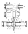
図4,図5はコンバインの走行装置11を示すもので、前記車台9の下面側に縦方向で中央寄りの左右位置に接合した左右の縦フレーム46の前側下部に箱状に形成した前部支持枠47を固着し、この左右の前部支持枠47に固定した前部ローリングメタル48に回動可能に軸支した左右の前部ローリング軸49に、側面視く字状の左右の前部ローリングアーム50を軸支する。該左右の縦フレ−ム46の後側下部に各々固定したピッチングメタル51にピッチング軸52を回動可能に軸支し、このピッチング軸52の左右側端部に左右のピッチングアーム53の一端部を軸止すると共に、その他端部と、平面視H字状の連結アーム54の左右側の一端部とを回動可能に各々ピン55により連結して構成させる。
【0022】
該連結アーム54の左右側他端部に回動可能に軸支した左右の後部ローリング軸56に、側面視く字状の左右の後部ローリングアーム57を軸支すると共に、該左右の前部ローリングアーム50の下端部位置と、左右の後部ローリングアーム57の下端部位置とを、左右の縦フレ−ム46の外側下方に各々位置する左右のクローラフレーム58の、前部側位置と後部側位置とに各々回動可能にピン59,60により連結させる。該右のピッチングアーム53の他端部を上方へ延長し、この延長した上端部と、前記車台9の後部側上面に設けた油圧等によって伸縮作用するピッチングシリンダ61のピストン先端部とをピン連結すると共に、このピッチングシリンダ61の固定側を該車台9の適宜位置に回動可能にピン連結して構成させる。
【0023】
該左右の前部ローリングアーム50の上端部と、左右の後部ローリングアーム57の上部中間位置とを各々4点平行リンクを形成可能に左右の連杆62によって回動可能にピン連結すると共に、該左右の後部ローリングアーム57の上端部を連杆62の連結位置より更に上方側へ延長し、その上端部と、油圧等によって伸縮作用する左右のローリングシリンダ63のピストン63aの先端部とを各々ピン64により連結させる。該左右のローリングシリンダ63の固定側から、左右のピッチングアーム53の他端部から突出させた突起部に向けて延長した帯状の保持板65を、各々両側より挾む状態で回動可能に突起部に対しピン66により連結し、該固定側の連結部をリンク67を介して揺動可能に該車台9の適宜位置に各々ピン連結して構成させる。
【0024】
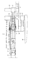
前記ピッチングシリンダ61の伸縮ストロークを検出する前後ストロークセンサ68を該シリンダ61の下部側に設け、このセンサ68の作用アームとピッチングアーム53上端部近傍とをロット69により連結する。該左右のローリングシリンダ63の伸縮ストロークを検出する左右ストロークセンサ70を、該後部ローリングアーム57のピン64上方側に配置可能に取り付けた断面L字状で帯状のセンサ取付板71を該シリンダ63の上面部に固定して設け、該ストロークセンサ70を作用させるセンサアーム70aをピン64に長孔により係合させると共に、該ストロークセンサ70自体又はセンサ取付板71を調節孔等により該シリンダ63の伸縮方向に位置調節可能に構成させる。
【0025】
前記左右のクローラフレーム58の後端上部側に、各々左右の後部転輪72を回動可能に支持する後部転輪受73を後方に向け固着すると共に、該左右のクローラフレーム58の下部側に各々所定の間隔をおいて複数箇の接地転輪74を遊転自在に軸支し、これら左右の後部転輪72及び複数箇の接地転輪74と、前記ミッションケース27から動力を伝達する左右の走行スプロケット44とに、前記左右の走行クローラ10を各々巻き掛け張設して構成させる。
【0026】
機体26の前後傾斜を検出する前後傾斜センサ75と、左右傾斜を検出する左右傾斜センサ76とを前記車台9のグレンタンク13下部側空間に配置し、該前後及び左右傾斜センサ75,76による傾斜状態の検出により機体26の水平状態への調整制御を自動的に行わせる前後スイッチ77及び左右スイッチ78と、機体26を昇降させる手動の車高スイッチ79とを各々前記操作装置22の一側に配置構成させる。
【0027】
図6に示す如く、CPUを主体的に配し自動回路の演算制御を行うと共に、左右水平作用を行うローリング機構と前後水平作用を行うピッチング機構の演算制御を行うコントローラ80を設け、このコントローラ80の入力側に、前記前後ストロークセンサ68,左右ストロークセンサ70,前後傾斜センサ75,左右傾斜センサ76,前後スイッチ77,左右スイッチ78,車高スイッチ79等を各々接続すると共に、その出力側へ、前記ピッチングシリンダ61を作動させる伸長側のピッチング電磁弁81と短縮側のピッチング電磁弁82,左右のローリングシリンダ63を作動させる伸長側の左右のローリング電磁弁83と短縮側の左右のローリング電磁弁84,アンロード弁85等を各々接続して構成させる。
【0028】
機体26がピッチングを起こして前後側に傾斜するときは、前後スイッチ77のONと前後傾斜センサ75により傾斜を検出し、コントローラ80を制御してピッチングシリンダ61を作動させ、ピッチングアーム53の上下回動作用により、連結アーム54を介して左右の後部ローリングアーム57により左右のクローラフレーム58の後部側を前部ローリング軸49を支点として上下動させてピッチング制御を行わせると共に、機体26がローリングを起こして左右側に傾斜するときは、左右スイッチ78のONと左右傾斜センサ76により傾斜を検出し、コントローラ80を制御して左又は右のローリングシリンダ63を作動させ、前部及び後部ローリングアーム50,57と連杆62による平行リンク作用により左又は右のクローラフレーム58を上下動させてローリング制御を行わせる。
【0029】
このように機体26のローリング制御と共にピッチング制御を行うとき、ピッチングシリンダ61の作動によりピッチングアーム53が作用し、該アーム53の作用によって連結アーム54を介して左右の後部ローリング軸56により後部ローリングアーム57全体が上下揺動する。該アーム57の上下揺動に伴い左右のローリングシリンダ63が変位して車台9に固定することができないため、ピッチングアーム53の突起部と該シリンダ63の固定側とを保持板65によって変位可能にピン66連結している。
【0030】
このように変位するローリングシリンダ63の伸縮ストローク検出は、図6,図7に示す如く、従来では、該シリンダ63の上面部にストロークセンサ70を固定し、該センサ70のアームと後部ローリングアーム57のピン64とを長さ調整可能なターンバックル式のロットにより連結し、該ピン64の動きにより伸縮ストロークを検出するようにしていたため、部品点数が増加すると共に、周辺のレイアウトにも制約を受けてコスト高となる難点があった。
【0031】
そこで、これらの難点を改善するため、ローリングシリンダ63の上面部に伸縮ストローク方向に調整可能に固定したセンサ取付板71に、ストロークセンサ70を後部ローリングアーム57のピン64上方側に配置可能に取り付けることにより、該センサ70を作用させるセンサアーム70aの先端長孔を直接該ピン64に係合させ、該ピン64の動きにより該シリンダ63の伸縮ストロークを検出させることができるから、ターンバックル式のロット等の省略による部品点数の削減と周辺レイアウトへの制約の緩和により、コスト低減並びに軽量化を図りうると共に、該センサ70への泥水等の飛散を少なくすることができる。
【図面の簡単な説明】
【図1】 走行ミッションケースの伝動機構を示す正断面図。
【図2】 走行ミッションケースの副変速の変速切り替え状態を示す正面図。
【図3】 走行ミッションケースの入力軸と変速軸受の油による潤滑状態を示す正面図。
【図4】 走行装置における走行クローラの昇降機構関係を示す側面図。
【図5】 走行装置における走行クローラの昇降機構関係を示す平面図。
【図6】 走行装置の前後水平制御及び左右水平制御の自動回路を示すブロック図。
【図7】 走行装置における左右ストロークセンサの取り付け関係を示す側面図。
【図8】 走行装置における左右ストロークセンサの取り付け関係を示す平面図。
【図9】 コンバインの全体構成を示す側面図。
【符号の説明】
1 無段変速装置
2 入力軸
2a スプライン
3 変速駆動ギヤ
3a クラッチ爪
3b 中速駆動ギヤ
3c 低速駆動ギヤ
4 高速駆動ギヤ
4a クラッチ爪
5 変速軸
6 高速従動ギヤ
7 中速従動ギヤ
8 低速従動ギヤ
9 車台
10 走行クローラ
13 グレンタンク
33 操向軸
35 操向クラッチ
35b クラッチギヤ
41 減速ギヤ
43 車軸
44 走行スプロケット
45 ボールベアリング
46 縦フレーム
47 前部支持枠
48 ローリングメタル
49 前部ローリング軸
50 前部ローリングアーム
51 ピッチングメタル
52 ピッチング軸
53 ピッチングアーム
54 連結アーム
55 回動可能にピン
56 後部ローリング軸
57 後部ローリングアーム
58 クローラフレーム
61 ピッチングシリンダ
62 連杆
63 ローリングシリンダ
63a ピストン
64 ピン
65 保持板
67 リンク
68 前後ストロークセンサ
69 ロッド
70 ストロークセンサ
70a センサアーム
71 センサ取付板
72 後部転輪
74 接地転輪
75 前後傾斜センサ
76 左右傾斜センサ
H 高速
M 中速
L 低速[0001]
BACKGROUND OF THE INVENTION
This invention,NvineIs aboutThe
[0002]
[Prior art]
The power output from the continuously variable transmission by hydraulic pressure that performs the main speed change of the vehicle speed in the work vehicle is input to the traveling transmission case that houses the gear transmission mechanism to change the vehicle speed, and to control the left and right sides of the aircraft. In a sub-shift type that performs a turning operation, etc., in which a high speed as a traveling speed by this speed change and a medium speed and a low speed three-speed speed as a working speed are switched by gear meshing.There is.
In addition, the detection of the expansion / contraction stroke of the rolling cylinder that controls the rolling of the fuselage is achieved by fixing a stroke sensor on the upper surface of the rolling cylinder and adjusting the length of the arm of the stroke sensor and the pin of the rear rolling arm. It was connected by a rod of the type, and the expansion / contraction stroke was detected by the movement of the pin.
[Problems to be solved by the invention]
Prior artHowever, when the operator turns on and off at high speed by operating the speed change lever, there is a problem that gear squealing occurs due to the meshing of the gears, and the operation feeling becomes worse, and smooth speed change switching cannot be performed. It was.
In addition, since the expansion / contraction stroke of the rolling cylinder is detected with the above-described configuration, the number of parts increases, and there is a problem that the cost is high due to restrictions on the peripheral layout.
[0003]
[0004]
[Means for Solving the Problems]
This invention relates to a continuously variable transmission.(1)Input shaft to input power from(2)Clutch claws(3a)On one side and double medium speed drive gear(3b)And low speed drive gear(3c)Variable speed drive gear consisting of(3)The spline(2a)Can be slid left and right, and can be arranged freely at one end(4a)High speed drive gear with one side(4)And the input shaft(2)Shifting shaft opposite to(5)High-speed driven gear(6)And the transmission shaft(5)Medium speed driven gear(7)And low-speed driven gear(8)And the speed change drive gear(3)Medium speed drive gear(3b)And low-speed drive gear(3c)The medium speed as the working speed(M)And slow(L)Speed change as well as high speed as traveling speed(H)The gear shift drive gear(3)Clutch claws(3a)And high speed drive gear(4)Clutch claws(4a)And connectThe power transmitted from the transmission shaft (5) to the steering shaft (33) is transmitted to the left and right reduction gears (41) via the left and right steering clutches (35, 35) and the left and right reduction gears ( 41) to the left and right axles (43, 43), and a low-speed driven gear (8) fixed to the transmission shaft (5) is formed in a dish shape so that the end of the transmission shaft (5) is formed. A ball bearing (45) to be supported bites into the inside of the low-speed driven gear (8), and the low-speed driven gear (8) and the baud The low-speed driven gear (8) receives the oil scooped up from the right reduction gear (41) through the clutch gear (35b) of the right steering clutch (35) by overlapping the bearing (45). The left and right vertical frames (46, 46) are attached to the lower surface side of the chassis (9) and the left and right vertical frames (46) are attached to the front lower portions of the left and right vertical frames (46). The front support frame (47) is fixed, and the left and right front rolling shafts (49, 49) are pivotally supported on the rolling metal (48, 48) fixed to the left and right front support frames (47). The left and right front rolling shafts (49, 49) are pivotally supported by the front rolling arms (50, 50) having a letter-like shape when viewed from the side, and are mounted on the lower rear portions of the left and right vertical frames (46, 46). Fixed pin A pitching shaft (52) is pivotally supported on the ching metal (51, 51), and one end of the left and right pitching arms (53, 53) is fixed to the left and right ends of the pitching shaft (52). In addition, the other ends of the left and right pitching arms (53, 53) and the left and right ends of a connecting arm (54) formed in an H shape in plan view are rotatably connected by pins (55, 55), While supporting the left and right rear rolling arms (57, 57) in a side view on the left and right rear rolling shafts (56, 56) pivotally supported on the other left and right ends of the connecting arm (54), The lower ends of the left and right rear rolling arms (57, 57) and the lower ends of the left and right front rolling arms (50, 50) are respectively connected to the front and rear portions of the left and right crawler frames (58, 58). Rotately connected, the left The other end of the right pitching arm (53) of the pitching arms (53, 53) is extended upward and provided on the upper end of the right pitching arm (53) and above the chassis (9). The piston front end of the pitching cylinder (61) is connected and the fixed side of the pitching cylinder (61) is connected to the rear end of the chassis (9), so that the left and right front rolling arms (50, 50) are connected. And the upper and lower intermediate positions of the left and right rear rolling arms (57, 57) are pivotally connected by left and right linkages (62, 62) and the upper ends of the left and right rear rolling arms (57, 57). The upper part of the piston (63a, 63a) of the left and right rolling cylinders (63, 63) is connected to the upper end of the connecting part (62, 62). Left and right belt-like holding plates (65, 65) connected to the protrusions on the other end of the left and right pitching arms (53, 53) are provided so as to sandwich both sides of the left and right rolling cylinders (63, 63). The connecting portion between the fixed side of the left and right rolling cylinders (63, 63) and the left and right holding plates (65, 65) can swing with respect to the chassis (9) via the left and right links (67, 67). A front / rear stroke sensor (68) for detecting the expansion / contraction stroke of the pitching cylinder (61) is provided on the lower side of the pitching cylinder (61), and the working arm of the front / rear stroke sensor (68) and the right pitching arm are connected. (53) is connected to the vicinity of the upper end portion by a rod (69), and strip-shaped sensor mounting plates (71, 71) are attached to the upper surface of the left and right rolling cylinders (63, 63). The left and right stroke sensors (70, 70) for detecting the expansion / contraction strokes of the left and right rolling cylinders (63, 63) are fixed to the sensor mounting plates (71, 71). The sensor arms (70a, 70a) are connected to pins (64, 64) that connect the upper ends of the rear rolling arms (57, 57) and the tips of the pistons (63a, 63a) of the rolling cylinders (63, 63). Driven by a plurality of ground rollers (74, 74) and rear wheels (72, 72) and the left and right axles (43, 43) which are engaged with the holes and attached to the left and right crawler frames (58, 58). Front and rear tilt sensors (7, 7) that wrap around the left and right traveling crawlers (10, 10) over the traveling sprockets (44, 44) ) And the lateral inclination sensor (76) for detecting the lateral inclination of the machine body and arranged in the lower part space grain tank (13) in the chassis (9)It is characterized byCombineThe configuration is as follows.
[0005]
With the above-described configuration, a gear transmission mechanism having a sub-shift that shifts the output to three stages of high, medium, and low is performed by a continuously variable transmission 1 using hydraulic pressure or the like in a work vehicle, and the output is shifted to three stages of high, middle, and low The medium
[0006]
The shift outputs switched to these high speed H, medium speed M, and low speed L are linked from the
[0007]
【The invention's effect】
As described above, with respect to the medium speed M and the low speed L as the work speed in the traveling mission case of the work vehicle, the medium
Further, the oil scooped up from the large-diameter gear 41a of the
Further, by attaching the
[0008]
DETAILED DESCRIPTION OF THE INVENTION
Below, the example of this invention is described based on a drawing about the combine as an agricultural work vehicle.
FIG. 9 shows the overall structure of the combine. A
[0009]
In front of the threshing
[0010]
An
[0011]
A traveling
[0012]
The
[0013]
The steering
The left and
[0014]
The
[0015]
At the time of the cutting operation, power is transmitted from the
[0016]
Next, when switching to the medium speed M as the work speed, the
[0017]
The power shifted in three stages by these sub-shifts is transmitted from the
[0018]
The steering
As described above, for the low speed L and the medium speed M as the work speed in the sub-shift, the normal shift switching by the direct meshing of the gear is performed, but for the high speed H as the traveling speed, the
[0019]
Further, as shown in FIG. 3, an oil reservoir hole a is penetrated in the diametrical direction at the position of the
[0020]
Since the lubrication is good when the
Further, as shown in FIG. 3, the shape of the low-speed driven
[0021]
4 and 5 show a
[0022]
The left and right
[0023]
The upper ends of the left and right
[0024]
A front /
[0025]
The
[0026]
A front / rear inclination sensor 75 for detecting the front / rear inclination of the
[0027]
As shown in FIG. 6, a
[0028]
When the
[0029]
When the pitching control is performed together with the rolling control of the
[0030]
The expansion / contraction stroke detection of the rolling
[0031]
Therefore, in order to improve these disadvantages, the
[Brief description of the drawings]
FIG. 1 is a front sectional view showing a transmission mechanism of a traveling mission case.
FIG. 2 is a front view showing a shift switching state of a sub-shift of a traveling mission case.
FIG. 3 is a front view showing a lubrication state of an input shaft and a transmission bearing of a traveling mission case with oil.
FIG. 4 is a side view showing a relationship of a lifting mechanism of a traveling crawler in a traveling device.
FIG. 5 is a plan view showing the relationship of a lifting mechanism of a traveling crawler in a traveling device.
FIG. 6 is a block diagram showing an automatic circuit for front-rear horizontal control and left-right horizontal control of the traveling device.
FIG. 7 is a side view showing a mounting relationship of a left / right stroke sensor in the traveling device.
FIG. 8 is a plan view showing a mounting relationship of left and right stroke sensors in the traveling device.
FIG. 9 is a side view showing the overall configuration of the combine.
[Explanation of symbols]
1 continuously variable transmission
2 Input shaft
2a spline
3 Variable speed drive gear
3a Clutch claw
3b Medium speed drive gear
3c Low speed drive gear
4 High-speed drive gear
4a Clutch claw
5 Transmission shaft
6 High-speed driven gear
7 Medium-speed driven gear
8 Low-speed driven gear
9 chassis
10 Traveling crawler
13 Glentank
33 Steering axis
35 Steering clutch
35b Clutch gear
41 Reduction gear
43 axle
44 Traveling sprocket
45 Ball bearing
46 Vertical frame
47 Front support frame
48 Rolling metal
49 Front rolling shaft
50 Front rolling arm
51 Pitching metal
52 Pitching shaft
53 Pitching arm
54 Linking arm
55 Rotating pin
56 Rear rolling shaft
57 Rear rolling arm
58 crawler frame
61 Pitching cylinder
62 ream
63 Rolling cylinder
63a piston
64 pins
65 Holding plate
67 links
68 Longitudinal stroke sensor
69 Rod
70 Stroke sensor
70a Sensor arm
71 Sensor mounting plate
72 Rear wheel
74 Ground wheel
75 Longitudinal tilt sensor
76 Left / right tilt sensor
H High speed
M Medium speed
L Low speed
Claims (1)
Priority Applications (1)
| Application Number | Priority Date | Filing Date | Title |
|---|---|---|---|
| JP02735498A JP3738552B2 (en) | 1998-02-09 | 1998-02-09 | Combine |
Applications Claiming Priority (1)
| Application Number | Priority Date | Filing Date | Title |
|---|---|---|---|
| JP02735498A JP3738552B2 (en) | 1998-02-09 | 1998-02-09 | Combine |
Publications (2)
| Publication Number | Publication Date |
|---|---|
| JPH11230279A JPH11230279A (en) | 1999-08-27 |
| JP3738552B2 true JP3738552B2 (en) | 2006-01-25 |
Family
ID=12218714
Family Applications (1)
| Application Number | Title | Priority Date | Filing Date |
|---|---|---|---|
| JP02735498A Expired - Fee Related JP3738552B2 (en) | 1998-02-09 | 1998-02-09 | Combine |
Country Status (1)
| Country | Link |
|---|---|
| JP (1) | JP3738552B2 (en) |
Families Citing this family (5)
| Publication number | Priority date | Publication date | Assignee | Title |
|---|---|---|---|---|
| US8308370B2 (en) | 2008-02-25 | 2012-11-13 | Jtekt Corporation | Sealing device for bearing |
| CN103307225B (en) * | 2013-06-27 | 2015-11-25 | 徐州五洋科技股份有限公司 | A kind of drive unit for mining water quality twin filter backwash mechanism |
| CN106286818A (en) * | 2015-05-28 | 2017-01-04 | 安徽赛威机械有限公司 | A kind of transmission clutch shifting device |
| CN106561167B (en) * | 2016-11-15 | 2018-03-20 | 金华职业技术学院 | A kind of motive power of combine harvester system |
| CN108386498A (en) * | 2018-01-29 | 2018-08-10 | 宁波大叶园林设备股份有限公司 | Gardens machine drives retarder with electronic crossed helical gears without planet rear axle |
-
1998
- 1998-02-09 JP JP02735498A patent/JP3738552B2/en not_active Expired - Fee Related
Also Published As
| Publication number | Publication date |
|---|---|
| JPH11230279A (en) | 1999-08-27 |
Similar Documents
| Publication | Publication Date | Title |
|---|---|---|
| JP3738552B2 (en) | Combine | |
| JP2004217071A (en) | Turning control device for traveling vehicles, etc. | |
| JP2004028136A (en) | Parking brake device for traveling vehicles, etc. | |
| JP4608826B2 (en) | Combine drive transmission | |
| JP2000245239A (en) | Harvest stop device for combine harvesters | |
| JP3198692B2 (en) | Combine traveling equipment | |
| JP2001328557A (en) | Traveling equipment such as work vehicles | |
| JP3972678B2 (en) | Combine drive transmission | |
| JP3395258B2 (en) | Combine | |
| JP3570014B2 (en) | Combine steering and turning control device | |
| JPH07125647A (en) | Revolving device such as combine | |
| JP2003274707A (en) | Direction control device such as combine | |
| JP4475006B2 (en) | Combine | |
| JP4153109B2 (en) | Work vehicle | |
| JP4449957B2 (en) | Combine | |
| JPH11196655A (en) | Work vehicle | |
| JP4422233B2 (en) | Work vehicle | |
| JPH0920270A (en) | Chassis lifting device for endless track type traveling vehicle | |
| JP2000245240A (en) | Harvesting transmissions such as combine harvesters | |
| JPH09188279A (en) | Combine crawler traveling device | |
| JPH05301580A (en) | Steering control device such as combine | |
| JP4153110B2 (en) | Work vehicle | |
| JP3620056B2 (en) | Combine traveling device | |
| JPH0986432A (en) | Steering and turning control device for work vehicle | |
| JP2002142541A (en) | Wetland lifting / lowering horizontal equipment such as combine |
Legal Events
| Date | Code | Title | Description |
|---|---|---|---|
| A977 | Report on retrieval |
Free format text: JAPANESE INTERMEDIATE CODE: A971007 Effective date: 20050422 |
|
| A131 | Notification of reasons for refusal |
Free format text: JAPANESE INTERMEDIATE CODE: A131 Effective date: 20050524 |
|
| A521 | Written amendment |
Free format text: JAPANESE INTERMEDIATE CODE: A523 Effective date: 20050725 |
|
| TRDD | Decision of grant or rejection written | ||
| A01 | Written decision to grant a patent or to grant a registration (utility model) |
Free format text: JAPANESE INTERMEDIATE CODE: A01 Effective date: 20051011 |
|
| A61 | First payment of annual fees (during grant procedure) |
Free format text: JAPANESE INTERMEDIATE CODE: A61 Effective date: 20051024 |
|
| R150 | Certificate of patent or registration of utility model |
Free format text: JAPANESE INTERMEDIATE CODE: R150 |
|
| FPAY | Renewal fee payment (event date is renewal date of database) |
Free format text: PAYMENT UNTIL: 20081111 Year of fee payment: 3 |
|
| FPAY | Renewal fee payment (event date is renewal date of database) |
Free format text: PAYMENT UNTIL: 20111111 Year of fee payment: 6 |
|
| LAPS | Cancellation because of no payment of annual fees |