JP3750077B2 - Obstacle detection device for electric shutter for building - Google Patents

Obstacle detection device for electric shutter for building Download PDF

Info

Publication number
JP3750077B2
JP3750077B2 JP2000137291A JP2000137291A JP3750077B2 JP 3750077 B2 JP3750077 B2 JP 3750077B2 JP 2000137291 A JP2000137291 A JP 2000137291A JP 2000137291 A JP2000137291 A JP 2000137291A JP 3750077 B2 JP3750077 B2 JP 3750077B2
Authority
JP
Japan
Prior art keywords
seat plate
piece
obstacle
shutter curtain
detection device
Prior art date
Legal status (The legal status is an assumption and is not a legal conclusion. Google has not performed a legal analysis and makes no representation as to the accuracy of the status listed.)
Expired - Fee Related
Application number
JP2000137291A
Other languages
Japanese (ja)
Other versions
JP2001317278A (en
Inventor
嘉宏 大塚
義孝 田栗
孝信 栗林
靖 山本
信也 岩崎
Current Assignee (The listed assignees may be inaccurate. Google has not performed a legal analysis and makes no representation or warranty as to the accuracy of the list.)
Sanwa Shutter Corp
Original Assignee
Sanwa Shutter Corp
Priority date (The priority date is an assumption and is not a legal conclusion. Google has not performed a legal analysis and makes no representation as to the accuracy of the date listed.)
Filing date
Publication date
Application filed by Sanwa Shutter Corp filed Critical Sanwa Shutter Corp
Priority to JP2000137291A priority Critical patent/JP3750077B2/en
Publication of JP2001317278A publication Critical patent/JP2001317278A/en
Application granted granted Critical
Publication of JP3750077B2 publication Critical patent/JP3750077B2/en
Anticipated expiration legal-status Critical
Expired - Fee Related legal-status Critical Current

Links

Images

Landscapes

  • Operating, Guiding And Securing Of Roll- Type Closing Members (AREA)

Description

【0001】
【発明の属する技術分野】
本発明は、ビル、住宅等の建造物の窓や出入り口等の開口部に建付けられる建築用電動シャッターにおける障害物検知装置の技術分野に属するものである。
【0002】
【従来の技術】
一般に、この種建築用電動シャッターのなかには、シャッターカーテンの閉鎖作動時に障害物があったような場合に、該障害物を検知して緊急停止させるための障害物検知装置が設けられているものがある。このような障害物検知装置としては、シャッターカーテン最下端に設けられる座板を上側座板と下側座板とに分割し、下側座板を上側座板に対して上下動自在に構成し、下側座板の上動に基づいて障害物検知をするようにしたものが知られている。そしてこの場合に、障害物検知装置としては、障害物検知に基づいて出力する検知スイッチからの検知信号を受けて、躯体上方に配した光受信部に対し遠赤外線等の光を送信する光送信部を配したものが知られている。
【0003】
【発明が解決しようとする課題】
しかるに、このような光送信式のものでは、精度の高い光軸合せが要求されるため、シャッターカーテンの左右方向位置を撓みの大きい左右方向中央部ではなく一側部に位置させると共に、シャッターカーテンの前後方向一側面(例えば屋内側面)から突出する状態で設ける必要がある。このため、送信部がシャッターカーテンのカーテン面から大きくはみ出す状態となっていて、設計の自由度が損なわれたり、意匠性に劣るばかりでなく、シャッターカーテンを全開状態とするためにまぐさ部に大開口を形成しなければならない等の問題があり、ここに本発明が解決しようとする課題があった。
【0004】
【課題を解決するための手段】
本発明は、上記の如き実情に鑑み、これらの課題を解決することを目的として創作されたものであって、請求項1の発明は、シャッターカーテンの座板が障害物に当接したことを検知して障害物回避作動を行う障害物検知装置であって、該障害物検知装置を、障害物検知に基づく検知信号を受けて躯体上方に設けられる受信部に対して無線送信する送信部を備えて構成するにあたり、送信部はシャッターカーテンに前後方向を向くよう屋内側に形成の凹部に対し、シャッターカーテンの前後寸法から突出しないようにして設けられるものとし、送信部に設けられるアンテナには、前記凹部の開口側に偏寄するよう屋内側に向けて突出する第一アンテナ片と、凹部の上側の溝側面から離れるよう第一アンテナ片の先端から下方に向けて折曲形成されることで下側に向けて偏寄した第二アンテナ片とが形成されている建築用電動シャッターにおける障害物検知装置である。
そして、このようにすることにより、アンテナの送信性の向上が計れて、送信部を殊更突出状に設ける必要がなくなる。
請求項2の発明は、請求項1において、座板は上側座板と、該上側座板に対し上下動自在に構成された下側座板とで構成され、送信部は上側座板に形成された凹部の左友方向略中央部に位置し、かつシャッターカーテン面と略面一状となるように配されている建築用電動シャッターにおける障害物検知装置である。
【0005】
【発明の実施の形態】
次に、本発明の第一の実施の形態を図1〜図7に示す図面に基づいて説明する。図面において、1は建築物の開口部を開閉するシャッターカーテンであって、該シャッターカーテン1は、開口部上方に設けられたシャッターケース2に内装された巻取りドラム3に巻装されている。そして、無線の操作具(リモートコントローラー)4の操作に基づく開閉機5の駆動に伴い巻取りドラム3が正逆回動し、これによって、巻取りドラム3に巻出し、巻取りされるシャッターカーテン1が、開口部に立設されたガイドレール6に両側部を移動案内される状態で開口部を開閉作動するように設定されており、これらの構成は何れも従来通りとなっている。
尚、5aは開閉機5を駆動制御するための制御部であって、該制御部5aには、シャッターケース2に設けられ、操作具4からの信号を受信する受信部を構成するアンテナ5bが接続されている。そして、制御部5aは、アンテナ5bからの受信信号に基づいて開閉機5に対して必要な駆動信号を出力するように設定されている。
【0006】
前記シャッターカーテン1は、一連状にインターロック結合された複数枚のスラット1aの最下端に座板7が連結されたものに構成されている。前記座板7は、前記スラット1aのうち最下端のスラット1aに連結される上側座板9と、該上側座板9に対し相対的に上下動自在に形成された下側座板10とにより構成されている。尚、本実施の形態の上側座板としては、上側座板9に上側スラット1aと連結するための連結ピース8を備えて構成されている。
前記上側座板9は、前片部9aと、該前片部9aから後方(屋内側)に向けて延出され、前記スラット1aと略同様の前後厚となるべく前後方向長さに設定された上片部9bと、前記前片部9aの上下方向中間部から後方に向けて延出され、前記上片部9bにより設定される前後長さとなるべく設定される中間片部9cと、該中間片部9cの後端縁から下方に向けて延出し、前記前片部9aの下端縁と互いに対向するべく設定される後片部9dとが一体形成されている。これによって、上側座板9の上方には上片部9bと前片部9aと中間片部9cとにより三方を囲まれた屋内外方向を向く凹部に形成され、該凹部が取付けスペースS1となるように設定されている。また、下方には前片部9aと中間片部9cと後片部9dとにより三方を囲まれ、下方が開口した検知スペースS2が形成される設定となっている。さらに、前、後片部9a、9dの互いに対向する面(検知スペースS2内側の面)には、下端部に位置して係止下片9eがそれぞれ対向形成されていると共に、検知スペースS2の上部に位置して係止上片9fがそれぞれ対向形成されている。
尚、上側座板上片部9bには、前後端部から上方に向けてそれぞれ係合片9g、9hが一体形成されており、これら係合片9g、9hを前記連結ピース8の係合受け片8a、8bにスライド移動自在かつ上下方向抜止め状に嵌合することで上側座板9と連結ピース8との連結がなされ、さらに、連結ピース8の上端部のインターロック部8cを、最下端スラット1aのインターロック部に連結することで、上側座板9と最下端スラット1aとの連結がなされる設定となっている。因みに、上側座板の上端縁部にインターロック部を形成し、最下端スラットに直接連結する構成としてもよく、この場合では連結ピースは不要となる。
【0007】
前記下側座板10には、前記上側座板検知スペースS2に出没自在に嵌合する本体部10aが形成されており、該本体部10aの上端部に、前記検知スペースS2の前後幅と略同用の前後長さに設定され、係止上片9fと係止下片9eとのあいだを上下移動する抜止め片10bが一体形成されている。また、下側座板10の下端部には、屋内外方向に長く形成され開口部上方のまぐさ部(開口部)を覆蓋するように設定された検知片部10cが一体に形成されている。そして、上側座板9の検知スペースS2に抜止め片10bを左右方向からスライド嵌合させることで、上側座板9と下側座板10との上下方向の抜止めがなされた状態の連結がなされ、下側座板10は、自然状態において抜止め片10bが上側座板係止下片9eに係止して上側座板9に吊持状に支持される下動姿勢から、下側座板10が上側座板9に対して相対的に上動、つまり、抜止め片10bが検知スペースS2内を上動して、抜止め片10bが係止上片9fに係合してこれ以上の上動が規制される上動姿勢までのあいだを上下移動可能となるように構成されている。これによって、シャッターカーテン1の閉鎖作動の過程で、開口部に障害物等があって下側座板10に当接したような場合に、下側座板10が上側座板9に対して相対上動するように設定される。因みに、前記下側座板10の上動姿勢では、検知片部10cが上側座板9の係止下片9e下面に当接する設定となっている。
【0008】
一方、11、12は、樹脂材で形成され、上側座板取付けスペースS1に取付けられる障害物検知装置のケーシングであって、各ケーシング11、12に障害物検知をする検知部と、該検知に伴い前記受信部5bに対して検知信号を送信する送信部とを構成するための必要部材をそれぞれ配することで、検知部と送信部とがそれぞれ分割可能に構成されている。
前記検知部ケーシング11には検知レバー11aが上下揺動自在に支持され、該検知レバー11aの下端部がケーシングの下片および上側座板中間片部9cに開設された貫通孔9iを介して検知スペースS2側に突出し、下側座板10が上側座板9に対して吊持される自然状態で下側座板抜止め片部10bの上面に近接対向する設定(丁度当接する設定でもよい)となっている。そして、下側座板10が障害物との当接等に基づいて相対上動したとき、下側座板抜止め片部10bが検知レバー11aを上側に押圧して、検知部ケーシング11内に配されたマイクロスイッチ(図示せず)をスイッチ切換えするように設定され、これによって障害物の検知がなされる。
【0009】
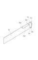
一方、送信部ケーシング12にはバッテリ(図示せず)が組込まれ、該バッテリに接続され、かつ検知部ケーシング11側のマイクロスイッチに接続される送信部回路を組込んだ基盤13が内装されている。前記基盤13は、送信部ケーシング12を上側座板取付けスペースS1に収納したとき取付けスペースS1の溝奥側、つまり屋外側に位置するようケーシング12に組込まれている。そして、前記基盤13に信号送信用のアンテナ14が電気的に接続されるが、該アンテナ14は、基端部が基盤13の上方位置で接続され、先端部が屋内側に向けて突出する都合三本の第一、第二、第三のアンテナ片14a、14b、14cと、前記第一、第二アンテナ片14a、14bの先端部間を連結する第一突出部14dと、第二、第三アンテナ片4b、14cの先端部間を連結する第二突出部14eとで形成されている。そして、前記第一突出部14dは第一、第二アンテナ片14a、14bを直線状に連結しており、これによって、該第一突出部14dが屋内側、つまり検知スペースS2の開口側に偏寄して位置するように設定されている。また、第二突出部14eはU字形状に折曲形成されており、中間部の折曲片部14fがアンテナ14の基盤13取付け位置よりも下方に位置し、ケース体12の上側片、つまり取付けスペースS1を構成する上側の溝側面となる上片部9bからは離間する側に偏寄して位置するよう配されている。
そして、検知部ケーシング11側のマイクロスイッチのスイッチ切換えがあった場合に、送信部ケーシング12側のアンテナ14から電波による無線の検知信号が出力される設定となっている。そして、この検知信号は、躯体開口部上方の制御部5aに接続される前記受信用のアンテナ5bを介して受信され、これに基づいて制御部5aが開閉機5に対して緊急停止指令を出力し、シャッターカーテン1の作動停止(障害物回避動作)がなされるように設定されている。
【0010】
さらに、これらケーシング11、12は、取付けスペースS1の左右方向略中央部に、左右方向(間口幅方向)に隣接する状態で配されており、このとき、各ケーシング11、12の上下長さ寸法は取付けスペースS1の上下長さと略同様になっていて、ケーシング11、12と上片部9bとのあいだが近接対向関係となるよう小さな隙間を存する状態で配されている。さらに、各ケーシング11、12は、前後厚さが薄型に形成されていて取付けスペースS1に各ケーシング11、12を取付けた状態の上側座板9の前後厚が、前記スラット1aの前後厚寸法から突出しない、即ち、スラット1a前後厚と同じになるかこれよりも薄くなるよう設定され、上側座板9がシャッターカーテン1面から大きくはみ出さないようになっている。
また、検知部ケーシング11に内装されるマイクロスイッチと、送信部ケーシング12に内装される基盤13側との接続は配線コードによる電気的な接続によりなされるが、これら検知部ケーシング11と送信部ケーシング12とは前述したように左右方向に隣接状に配されているので、マイクロスイッチと基盤13側とを接続する配線コードが各ケーシング11、12によりほぼ覆蓋されて露出することがないように設定されている。因みに、検知部と送信部とが一体に形成されているものであってもよく、分離型とした場合では、本実施の形態のように隣接状に配設することによって、配線コードの露出が回避される。
【0011】
さらに、各ケーシング11、12の上側座板取付けスペースS1への取付けは次のように設定されている。
つまり、各ケーシング11、12が取付けられる上側座板中間片部(取付けスペースS1の下側片)9cは、後面側ほど下位となる傾斜片部9jに形成されており、電気的な接続部(配線コード)を介して連結されている各ケーシング11、12の下片11b、12aは、前記中間片部9cに対向した傾斜状に形成されている。そして、検知部ケーシング下片11bの左右方向には傾斜片部9jに対向して傾斜した取付け片11c、11dが突出形成されており、検知部ケーシング11を中間片部9cにあてがい、取付け片11c、11dを傾斜片部9jに対し、シャッターカーテン1面の斜め上方から傾斜状に挿入される螺子15を用いて螺合することで、予め検知部ケーシング11が上側座板9に取付けられるように設定されている。続いて、送信部ケーシング12を取付けるが、送信部ケーシング12の下片12aの検知部ケーシング11隣接側には、前記検知部ケーシング取付け片11dを内嵌する凹部12bが形成され、その反対側部には取付け片12cが突出形成されている。そして、送信部ケーシング12を中間片部9cにあてがい、凹部12bが検知部ケーシング11の取付け片11dを内嵌する状態でセットし、そして、反対側の取付け片12cを傾斜片部9jに対して傾斜状に挿入される螺子15を用いて螺合することで、送信部ケーシング12が上側座板9に取付けられるように設定されている。因みに、送信部ケーシング12の凹部12bは、検知部ケーシング11の螺子15止めされた取付け部11dに対し保持状に外嵌されている。
このように、各ケーシング11、12の上側座板9への取付けを、シャッターカーテン1面の斜め上方から差し込まれる螺子15を用いて螺合する構成とすることで、螺合用工具を操作しやすく、組付け作業を容易にできるように配慮されている。さらに、中間片部9cを傾斜片部9jに形成することにより、排水機能を向上させて取付けスペースS1に水が溜ってしまうような不具合を回避するように配慮されている。
【0012】
叙述の如く構成された本発明の実施の形態において、シャッターカーテン1の閉鎖作動の過程で障害物があった場合に、該障害物に当接した検知片部10cと共に下側座板10が上側座板9に対して相対上動することになり、これに伴い、検知部ケーシング11から検知スペースS2側に延出した検知レバー11aが下側座板抜止め片部10bにより押し上げられて検知部ケーシング11内のマイクロスイッチがスイッチ切換えされ、しかして、送信部ケーシング12内に配されたアンテナ14から電波による検知信号が出力され、シャッターカーテン1の緊急停止(障害物回避動作)がなされるが、この場合に、アンテナ14はケーシング12内の屋内側に位置するよう、前記取付けスペースS1の開口側に偏寄して設けられていて、送信部ケーシング12はシャッターカーテン1の屋内側カーテン面と略面一状となっている。従って、従来の光送信式のもののように屋内外方向に突出させることなく送信することができて、設計の自由度が増加するうえ、意匠性に優れるばかりでなく、シャッターカーテン1の全開時において、送信部が設けられる座板7部位を、まぐさを越えて上方にまで巻取ることも可能になる。
【0013】
しかもこのものでは、アンテナ14に第二突出部14eには、取付けスペースS1を構成する上側の溝側面となる上片部9bから離れる側に偏寄して位置する折曲片14fが形成されていて、送信性がさらに優れたものになっている。
【0014】
さらに、このものでは光送信式のもののように精度の高い光軸合せの必要がない結果、送信部を撓みの発生しやすいシャッターカーテン1の左右方向略中央部に設けることもできる。しかも、検知部と送信部とはそれぞれ別個のケーシング11、12に配された分割型となっているので、組付け作業も容易であり、修理、点検、バッテリ交換等のメンテナンス作業が簡単に行えるという利点もある。
【0015】
尚、本発明は前記実施の形態に限定されることは勿論なく、図8に示す第二の実施の形態のようにすることもできる。このものは、アンテナ17の第一、第二アンテナ片17a、17b先端部とのあいだの第一突出部17dと、第二、第三アンテナ片17b、17c先端部とのあいだの第二突出部17eとに、前記第一の実施の形態の折曲片部14fと同様に、取付けスペースS1の上側の溝側面から離れるようにそれぞれ折曲させた折曲片部17f、17gが形成されたものとなっており、このようにしても同様の効果を得ることができる。
【図面の簡単な説明】
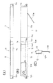
【図1】 障害物検知状態の建築用シャッター概略を説明する一部切欠き背面図である。
【図2】 図1の側面図である。
【図3】 建築用シャッターの要部の側面断図である。
【図4】 障害物検知装置の非検知状態を示す背面図である。
【図5】 図5(A)、(B)、(C)はそれぞれ障害物検知装置の平面図、背面図、側面図である。
【図6】 アンテナの取付け状態を示す斜視図である。
【図7】 シャッターカーテンの全開状態を示す一部省略側面断図である。
【図8】 第二の実施の形態におけるアンテナの取付け状態を示す斜視図である。
【符号の説明】
1 シャッターカーテン
3 巻取りドラム
5 開閉機
5b 受信部
7 座板
8 連結ピース
9 上側座板
10 下側座板
11 検知部ケーシング
11a 検知レバー
12 送信部ケーシング
13 基盤
14 アンテナ
14d 第一突出部
14f 折曲片部
S1 取付けスペース
S2 検知スペース
[0001]
BACKGROUND OF THE INVENTION
The present invention belongs to the technical field of an obstacle detection device in an electric shutter for building installed in an opening such as a window or an entrance of a building such as a building or a house.
[0002]
[Prior art]
In general, some of the electric shutters for buildings of this type are provided with an obstacle detection device for detecting an obstacle and making an emergency stop when there is an obstacle when the shutter curtain is closed. is there. As such an obstacle detection device, a seat plate provided at the lowermost end of the shutter curtain is divided into an upper seat plate and a lower seat plate, and the lower seat plate is configured to be movable up and down with respect to the upper seat plate. There is known one that detects an obstacle based on the upward movement of a lower seat plate. In this case, the obstacle detection device receives the detection signal from the detection switch that is output based on the obstacle detection, and transmits light such as far-infrared light to the optical receiver disposed above the housing. The thing which arranged the part is known.
[0003]
[Problems to be solved by the invention]
However, in such an optical transmission type, since the optical axis alignment with high accuracy is required, the left and right position of the shutter curtain is positioned on one side instead of the central portion where the deflection is large, and the shutter curtain It is necessary to provide in the state which protrudes from one side (for example, indoor side) of the front-back direction. For this reason, the transmission unit is in a state of protruding greatly from the curtain surface of the shutter curtain, not only the design freedom is impaired or inferior in design, but also in the lintel part to make the shutter curtain fully open. There is a problem that a large opening has to be formed, and there is a problem to be solved by the present invention.
[0004]
[Means for Solving the Problems]
The present invention has been created in view of the above-described circumstances and has been created for the purpose of solving these problems. The invention of claim 1 is that the seat plate of the shutter curtain is in contact with an obstacle. An obstacle detection device that detects and performs an obstacle avoidance operation, wherein the obstacle detection device receives a detection signal based on the obstacle detection and wirelessly transmits to the reception unit provided above the housing. in configuring comprises, antenna transmission unit, against the recess of the formation on the indoor side to face the front-rear direction on the shutter curtain, and shall be provided so as not to protrude from the front and rear dimensions of the shutter curtain, provided in the transmission unit the, a first antenna element which projects toward the interior side so as to biasing the open side of the recess, from the tip of the first antenna element away from the groove side surface of the upper recess downwardly bent Are obstacle detecting device in biasing the second antenna element and the building electric shutters which are formed toward the lower side made is that.
And by doing in this way, the transmission nature of an antenna can be improved and it is not necessary to provide a transmitting part in the shape of a projection in particular.
According to a second aspect of the present invention, in the first aspect, the seat plate is composed of an upper seat plate and a lower seat plate configured to be movable up and down with respect to the upper seat plate, and the transmitter is formed on the upper seat plate. This is an obstacle detection device for an electric shutter for building, which is located substantially at the center in the left friend direction of the recessed portion and is arranged so as to be substantially flush with the shutter curtain surface.
[0005]
DETAILED DESCRIPTION OF THE INVENTION
Next, a first embodiment of the present invention will be described based on the drawings shown in FIGS. In the drawings, reference numeral 1 denotes a shutter curtain that opens and closes an opening of a building. The shutter curtain 1 is wound around a winding drum 3 provided in a shutter case 2 provided above the opening. Then, the winding drum 3 rotates forward and backward in accordance with the driving of the opening / closing device 5 based on the operation of the wireless operation tool (remote controller) 4, whereby the shutter curtain is unwound and wound on the winding drum 3. 1 is set to open and close the opening in a state where both sides are moved and guided by the guide rail 6 erected on the opening, and these configurations are all conventional.
Reference numeral 5a denotes a control unit for driving and controlling the switch 5. The control unit 5a includes an antenna 5b that is provided in the shutter case 2 and that constitutes a receiving unit that receives a signal from the operation tool 4. It is connected. And the control part 5a is set so that a required drive signal may be output with respect to the switch 5 based on the received signal from the antenna 5b.
[0006]
The shutter curtain 1 is configured such that a seat plate 7 is connected to the lowermost ends of a plurality of slats 1a interlocked in series. The seat plate 7 includes an upper seat plate 9 connected to the lowermost slat 1a of the slats 1a, and a lower seat plate 10 formed so as to be movable up and down relatively with respect to the upper seat plate 9. It is configured. In addition, as an upper seat plate of this Embodiment, the upper seat plate 9 is provided with the connection piece 8 for connecting with the upper slat 1a.
The upper seat plate 9 extends from the front piece 9a toward the rear (indoor side) from the front piece 9a, and is set to have a length in the front-rear direction as much as possible in the front-rear thickness. An upper piece portion 9b, an intermediate piece portion 9c extending rearward from an intermediate portion in the vertical direction of the front piece portion 9a and set to have a longitudinal length set by the upper piece portion 9b, and the intermediate piece A rear piece portion 9d that extends downward from the rear end edge of the portion 9c and is set so as to face the lower end edge of the front piece portion 9a is integrally formed. As a result, the upper seat plate 9 is formed in a concave portion facing the indoor / outdoor direction surrounded by three sides by the upper piece portion 9b, the front piece portion 9a, and the intermediate piece portion 9c, and the concave portion becomes the attachment space S1. Is set to In addition, a detection space S2 that is surrounded on three sides by a front piece portion 9a, an intermediate piece portion 9c, and a rear piece portion 9d and that opens downward is formed. Further, the front and rear piece portions 9a and 9d are opposed to each other (the inner surface of the detection space S2), and a lower locking piece 9e is formed facing each other at the lower end portion. The upper locking pieces 9f are formed facing each other at the upper part.
Engagement pieces 9g and 9h are integrally formed on the upper seat plate upper piece 9b from the front and rear ends to the upper side, respectively. The upper seat plate 9 and the connecting piece 8 are connected by being slidably fitted to the pieces 8a and 8b and vertically secured so that the interlock portion 8c at the upper end of the connecting piece 8 is By connecting to the interlock portion of the lower end slat 1a, the upper seat plate 9 and the lowermost end slat 1a are connected. Incidentally, it is good also as a structure which forms an interlock part in the upper end edge part of an upper seat plate, and connects with a lowest end slat directly, and a connection piece becomes unnecessary in this case.
[0007]
The lower seat plate 10 is formed with a main body portion 10a that can be inserted into and retracted into the upper seat plate detection space S2, and the upper and lower widths of the detection space S2 are substantially equal to the upper end portion of the main body portion 10a. A retaining piece 10b that is set to the same longitudinal length and moves up and down between the locking upper piece 9f and the locking lower piece 9e is integrally formed. In addition, a detection piece 10c that is formed so as to cover the lintel (opening) above the opening and is formed integrally with the lower end of the lower seat plate 10 is formed integrally. . And by connecting the retaining piece 10b to the detection space S2 of the upper seat plate 9 from the left and right direction, the upper seat plate 9 and the lower seat plate 10 are connected in the state in which the upper seat plate 9 and the lower seat plate 10 are retained in the vertical direction. In the natural state, the lower seat plate 10 is moved from the lower movement position in which the retaining piece 10b is engaged with the upper seat plate engaging lower piece 9e and supported by the upper seat plate 9 in a suspended manner. The plate 10 moves upward relative to the upper seat plate 9, that is, the retaining piece 10b moves up in the detection space S2, and the retaining piece 10b engages with the locking upper piece 9f and beyond. It is configured to be able to move up and down until the upward movement posture where the upward movement is restricted. Thus, in the process of closing the shutter curtain 1, when there is an obstacle in the opening and the lower seat plate 10 comes into contact with the lower seat plate 10, the lower seat plate 10 is relative to the upper seat plate 9. Set to move up. Incidentally, in the upward movement posture of the lower seat plate 10, the detection piece portion 10 c is set to contact the lower surface of the locking lower piece 9 e of the upper seat plate 9.
[0008]
On the other hand, 11 and 12 are casings of an obstacle detection device that is formed of a resin material and is attached to the upper seat plate mounting space S1, a detection unit that detects an obstacle in each of the casings 11 and 12, and the detection. Accordingly, the detection unit and the transmission unit are each configured to be separable by arranging necessary members for configuring a transmission unit that transmits a detection signal to the reception unit 5b.
A detection lever 11a is supported on the detection portion casing 11 so as to be swingable up and down, and a lower end portion of the detection lever 11a is detected through a through hole 9i provided in a lower piece of the casing and an upper seat plate intermediate piece portion 9c. A setting that protrudes toward the space S2 and faces the upper surface of the lower seat plate retaining piece 10b in a natural state in which the lower seat plate 10 is suspended from the upper seat plate 9 (may be set just to abut) It has become. When the lower seat plate 10 moves relatively upward based on contact with an obstacle or the like, the lower seat plate retaining piece 10b presses the detection lever 11a upward, and enters the detector casing 11. An arranged micro switch (not shown) is set to be switched, whereby an obstacle is detected.
[0009]
On the other hand, a battery (not shown) is incorporated in the transmitter casing 12, and a base 13 incorporating a transmitter circuit connected to the battery and connected to a micro switch on the detection casing 11 side is incorporated. Yes. The base 13 is incorporated in the casing 12 so as to be positioned on the back side of the groove of the mounting space S1, that is, on the outdoor side, when the transmitter casing 12 is stored in the upper seat plate mounting space S1. Then, a signal transmission antenna 14 is electrically connected to the base 13. The antenna 14 has a base end connected at a position above the base 13 and a tip protruding toward the indoor side. Three first, second, and third antenna pieces 14a, 14b, and 14c, a first projecting portion 14d that connects the tip portions of the first and second antenna pieces 14a and 14b, and second and second three antenna element 1 4b, are formed by the second protruding portion 14e for connecting the distal end portion of the 14c. The first projecting portion 14d linearly connects the first and second antenna pieces 14a and 14b, so that the first projecting portion 14d is biased indoors, that is, toward the opening side of the detection space S2. It is set so as to be located close to each other. The second projecting portion 14e is bent in a U shape, and the bent portion 14f of the intermediate portion is located below the mounting position of the base 13 of the antenna 14, and the upper piece of the case body 12, that is, It arrange | positions so that it may be offset and located in the side spaced apart from the upper piece part 9b used as the upper groove side surface which comprises attachment space S1.
And when the switch of the micro switch by the side of the detection part casing 11 has been switched, the radio | wireless detection signal by the electromagnetic wave is output from the antenna 14 by the side of the transmission part casing 12. And this detection signal is received via the said receiving antenna 5b connected to the control part 5a above the housing opening, and based on this, the control part 5a outputs an emergency stop command to the switch 5. In addition, the shutter curtain 1 is set to stop operating (obstacle avoiding operation).
[0010]
Furthermore, these casings 11 and 12 are arranged in a state adjacent to the left and right direction (frontage width direction) at a substantially central portion in the left and right direction of the mounting space S1, and at this time, the vertical length of each casing 11 and 12 is determined. Is substantially the same as the vertical length of the mounting space S1, and is arranged between the casings 11 and 12 and the upper piece portion 9b with a small gap so as to be in close proximity. Further, the casings 11 and 12 are formed so that the front and rear thicknesses are thin, and the front and rear thicknesses of the upper seat plate 9 with the casings 11 and 12 mounted in the mounting space S1 are determined from the front and rear thickness dimensions of the slats 1a. It is set so as not to protrude, that is, to be equal to or thinner than the thickness of the slat 1a, so that the upper seat plate 9 does not protrude greatly from the surface of the shutter curtain 1.
Further, the connection between the micro switch built in the detection unit casing 11 and the base 13 side built in the transmission unit casing 12 is made by an electrical connection using a wiring cord. The detection unit casing 11 and the transmission unit casing are connected to each other. 12 is arranged so as to be adjacent in the left-right direction as described above, so that the wiring cord connecting the microswitch and the base 13 side is not covered and exposed by the casings 11, 12. Has been. Incidentally, the detection unit and the transmission unit may be integrally formed, and in the case of a separate type, the wiring cord is exposed by arranging adjacently as in the present embodiment. Avoided.
[0011]
Furthermore, the attachment of the casings 11 and 12 to the upper seat mounting space S1 is set as follows.
That is, the upper seat plate intermediate piece portion (the lower piece of the attachment space S1) 9c to which the casings 11 and 12 are attached is formed in the inclined piece portion 9j which is lower on the rear surface side, and an electrical connection portion ( The lower pieces 11b and 12a of the casings 11 and 12 connected via the wiring cords are formed in an inclined shape facing the intermediate piece portion 9c. And in the left-right direction of the detection part casing lower piece 11b, attachment pieces 11c and 11d inclined so as to face the inclination piece part 9j are formed so as to protrude, the detection part casing 11 is applied to the intermediate piece part 9c, and the attachment piece 11c. , 11d are screwed into the inclined piece portion 9j by using a screw 15 that is inserted obliquely from above the surface of the shutter curtain 1 so that the detector casing 11 is attached to the upper seat plate 9 in advance. Is set. Subsequently, the transmitter casing 12 is attached. On the side of the lower piece 12a of the transmitter casing 12 adjacent to the detector casing 11, a recess 12b for fitting the detector casing mounting piece 11d is formed, and the opposite side portion is formed. A mounting piece 12c is formed to protrude. Then, the transmitter casing 12 is set to the intermediate piece portion 9c, the recess 12b is set in a state in which the attachment piece 11d of the detection portion casing 11 is fitted, and the opposite attachment piece 12c is set to the inclined piece portion 9j. The transmitter casing 12 is set so as to be attached to the upper seat plate 9 by screwing using the screw 15 inserted in an inclined manner. Incidentally, the concave portion 12b of the transmission portion casing 12 is externally fitted in a holding shape to the attachment portion 11d of the detection portion casing 11 which is fixed to the screw 15.
As described above, the attachment of the casings 11 and 12 to the upper seat plate 9 is configured to be screwed using the screw 15 inserted obliquely from the upper surface of the shutter curtain 1 so that the screwing tool can be operated easily. Consideration has been given to facilitate assembly work. Further, by forming the intermediate piece portion 9c in the inclined piece portion 9j, consideration is given to improving the drainage function and avoiding a problem that water is accumulated in the mounting space S1.
[0012]
In the embodiment of the present invention configured as described above, when there is an obstacle in the process of closing the shutter curtain 1, the lower seat plate 10 is located on the upper side together with the detection piece 10c that is in contact with the obstacle. Accordingly, the detection lever 11a extending from the detection unit casing 11 to the detection space S2 side is pushed up by the lower side plate retaining piece 10b and accordingly the detection unit is moved upward relative to the seat plate 9. Although the micro switch in the casing 11 is switched, a detection signal by radio waves is output from the antenna 14 disposed in the transmitter casing 12, and the shutter curtain 1 is urgently stopped (obstacle avoiding operation). In this case, the antenna 14 is provided on the opening side of the mounting space S1 so as to be located on the indoor side in the casing 12, and the transmitting unit Pacing 12 has a indoor side curtain surface of the shutter curtain 1 and substantially flush shape. Therefore, it can transmit without projecting indoors and outdoors like the conventional optical transmission type, and the degree of freedom of design is increased, and it is not only excellent in design but also when the shutter curtain 1 is fully opened. It is also possible to wind up the seat plate 7 portion where the transmission unit is provided to the upper side beyond the lintels.
[0013]
In addition, in the antenna 14, the second protrusion 14e is formed with a bent piece 14f that is offset and located on the side away from the upper piece 9b that forms the side surface of the upper groove constituting the mounting space S1. Therefore, the transmission is further improved.
[0014]
Further, in this case, unlike the optical transmission type, it is not necessary to align the optical axis with high accuracy. As a result, the transmission unit can be provided at the substantially central portion in the left-right direction of the shutter curtain 1 where bending easily occurs. Moreover, since the detection unit and the transmission unit are divided into separate casings 11 and 12, assembly work is easy, and maintenance work such as repair, inspection, and battery replacement can be easily performed. There is also an advantage.
[0015]
Of course, the present invention is not limited to the above-described embodiment, and may be the second embodiment shown in FIG. This material comprises a first antenna 17, second antenna element 17a, the first projection portion 17d of between the 17b tip, second, third antenna element 17b, the second protrusion of between the 17c tip Like the bent piece portion 14f of the first embodiment, bent piece portions 17f and 17g that are bent away from the upper groove side surface of the mounting space S1 are formed on the portion 17e. Even in this way, the same effect can be obtained.
[Brief description of the drawings]
FIG. 1 is a partially cutaway rear view for explaining an outline of an architectural shutter in an obstacle detection state.
FIG. 2 is a side view of FIG.
FIG. 3 is a side sectional view of a main part of a building shutter.
FIG. 4 is a rear view showing a non-detection state of the obstacle detection device.
FIGS. 5A, 5B, and 5C are a plan view, a rear view, and a side view of the obstacle detection device, respectively.
FIG. 6 is a perspective view showing an antenna attachment state.
FIG. 7 is a partially omitted side sectional view showing a fully opened state of the shutter curtain.
FIG. 8 is a perspective view showing an antenna attachment state in the second embodiment.
[Explanation of symbols]
DESCRIPTION OF SYMBOLS 1 Shutter curtain 3 Winding drum 5 Opening and closing machine 5b Reception part 7 Seat plate 8 Connection piece 9 Upper seat plate 10 Lower seat plate 11 Detection part casing 11a Detection lever 12 Transmission part casing 13 Base 14 Antenna 14d First protrusion part 14f Folding Curved part S1 Installation space S2 Detection space

Claims (2)

シャッターカーテンの座板が障害物に当接したことを検知して障害物回避作動を行う障害物検知装置であって、該障害物検知装置を、障害物検知に基づく検知信号を受けて躯体上方に設けられる受信部に対して無線送信する送信部を備えて構成するにあたり、送信部はシャッターカーテンに前後方向を向くよう屋内側に形成の凹部に対し、シャッターカーテンの前後寸法から突出しないようにして設けられるものとし、送信部に設けられるアンテナには、前記凹部の開口側に偏寄するよう屋内側に向けて突出する第一アンテナ片と、凹部の上側の溝側面から離れるよう第一アンテナ片の先端から下方に向けて折曲形成されることで下側に向けて偏寄した第二アンテナ片とが形成されている建築用電動シャッターにおける障害物検知装置。An obstacle detection device that detects that the seat plate of the shutter curtain has come into contact with an obstacle and performs an obstacle avoidance operation. The obstacle detection device receives a detection signal based on the obstacle detection and receives the detection signal. in constituting a transmission unit that wirelessly transmits to the receiving portion provided in the transmission section, against the recess of the formation on the indoor side to face the front-rear direction on the shutter curtain, so as not to protrude from the front and rear dimensions of the shutter curtain shall be provided to, the antenna provided in the transmission section, a first antenna element which projects toward the interior side so as to biasing the open side of the recess, first away from the groove side surface of the upper recess An obstacle detection device in an electric shutter for building, in which a second antenna piece is formed by bending downward from the tip of one antenna piece and thereby being biased downward . 請求項1において、座板は上側座板と、該上側座板に対し上下動自在に構成された下側座板とで構成され、送信部は上側座板に形成された凹部の左友方向略中央部に位置し、かつシャッターカーテン面と略面一状となるように配されている建築用電動シャッターにおける障害物検知装置。  In Claim 1, a seat board is comprised by the upper seat board and the lower seat board comprised so that vertical movement was possible with respect to this upper seat board, and a transmission part is the left friend direction of the recessed part formed in the upper seat board. An obstacle detection device for an electric shutter for building, which is positioned substantially at the center and arranged to be substantially flush with the shutter curtain surface.
JP2000137291A 2000-05-10 2000-05-10 Obstacle detection device for electric shutter for building Expired - Fee Related JP3750077B2 (en)

Priority Applications (1)

Application Number Priority Date Filing Date Title
JP2000137291A JP3750077B2 (en) 2000-05-10 2000-05-10 Obstacle detection device for electric shutter for building

Applications Claiming Priority (1)

Application Number Priority Date Filing Date Title
JP2000137291A JP3750077B2 (en) 2000-05-10 2000-05-10 Obstacle detection device for electric shutter for building

Publications (2)

Publication Number Publication Date
JP2001317278A JP2001317278A (en) 2001-11-16
JP3750077B2 true JP3750077B2 (en) 2006-03-01

Family

ID=18645083

Family Applications (1)

Application Number Title Priority Date Filing Date
JP2000137291A Expired - Fee Related JP3750077B2 (en) 2000-05-10 2000-05-10 Obstacle detection device for electric shutter for building

Country Status (1)

Country Link
JP (1) JP3750077B2 (en)

Families Citing this family (4)

* Cited by examiner, † Cited by third party
Publication number Priority date Publication date Assignee Title
ITVE20080085A1 (en) * 2008-11-17 2010-05-18 Teleco Automation Srl MOTORIZED SECTIONAL DOOR UNIT.-
JP6219127B2 (en) * 2013-10-31 2017-10-25 三和シヤッター工業株式会社 Shutter obstacle detection system
JP6219128B2 (en) * 2013-10-31 2017-10-25 三和シヤッター工業株式会社 Shutter device
JP6308797B2 (en) * 2014-02-18 2018-04-11 三和シヤッター工業株式会社 Shutter obstacle detection system

Also Published As

Publication number Publication date
JP2001317278A (en) 2001-11-16

Similar Documents

Publication Publication Date Title
US20060076113A1 (en) Pair glass window and door system equipped with remote controllable auto blind
US7178291B2 (en) Automated shutter control
US10000968B2 (en) Electromechanical actuator and home automation installation comprising such an electromechanical actuator
US20140332168A1 (en) Automated Shutter Control
KR101301912B1 (en) Device for automatic opening and closing window
JP3750077B2 (en) Obstacle detection device for electric shutter for building
KR20210059520A (en) Photovoltaic lightshelf
US20220034161A1 (en) Electromechanical actuator comprising a module for filtering vibrations, and closure, covering or solar protection system comprising such an electromechanical actuator
JP3709280B2 (en) Shutter for building
WO2015099012A1 (en) Waterproof door
JP3707046B2 (en) Obstacle detection device for electric shutter for building
JP3707045B2 (en) Obstacle detection device for electric shutter for building
JP3755120B2 (en) Obstacle detection device for electric shutter for building
KR20180088177A (en) Remote controller for lamp switch
JP2012211491A (en) Abnormality stop device of electric shutter apparatus for building
JP7659488B2 (en) Opening and closing device
JP7213733B2 (en) Switchgear structure
JPH06123193A (en) Obstacle detection device when the shutter is descending
JP2023006049A (en) shutter
JP2002038856A (en) Closure device
JP3899632B2 (en) Wiring structure of electric switch
JP5610756B2 (en) Opening and closing body device
KR0139198Y1 (en) Rotatory angle control apparatus of a vertical automatic blind
JP2023168857A (en) Opening/closing device and opening/closing control method
JP2006063530A (en) Electronic lock emergency unlocking device

Legal Events

Date Code Title Description
A977 Report on retrieval

Free format text: JAPANESE INTERMEDIATE CODE: A971007

Effective date: 20050818

A131 Notification of reasons for refusal

Free format text: JAPANESE INTERMEDIATE CODE: A131

Effective date: 20050825

A521 Written amendment

Free format text: JAPANESE INTERMEDIATE CODE: A523

Effective date: 20051018

TRDD Decision of grant or rejection written
A01 Written decision to grant a patent or to grant a registration (utility model)

Free format text: JAPANESE INTERMEDIATE CODE: A01

Effective date: 20051110

A61 First payment of annual fees (during grant procedure)

Free format text: JAPANESE INTERMEDIATE CODE: A61

Effective date: 20051124

R150 Certificate of patent or registration of utility model

Free format text: JAPANESE INTERMEDIATE CODE: R150

FPAY Renewal fee payment (event date is renewal date of database)

Free format text: PAYMENT UNTIL: 20081216

Year of fee payment: 3

S111 Request for change of ownership or part of ownership

Free format text: JAPANESE INTERMEDIATE CODE: R313111

FPAY Renewal fee payment (event date is renewal date of database)

Free format text: PAYMENT UNTIL: 20081216

Year of fee payment: 3

R350 Written notification of registration of transfer

Free format text: JAPANESE INTERMEDIATE CODE: R350

LAPS Cancellation because of no payment of annual fees