JP3765780B2 - Electromagnetic field sensor - Google Patents
Electromagnetic field sensor Download PDFInfo
- Publication number
- JP3765780B2 JP3765780B2 JP2002258799A JP2002258799A JP3765780B2 JP 3765780 B2 JP3765780 B2 JP 3765780B2 JP 2002258799 A JP2002258799 A JP 2002258799A JP 2002258799 A JP2002258799 A JP 2002258799A JP 3765780 B2 JP3765780 B2 JP 3765780B2
- Authority
- JP
- Japan
- Prior art keywords
- electric field
- magnetic field
- detection unit
- field sensor
- transmission
- Prior art date
- Legal status (The legal status is an assumption and is not a legal conclusion. Google has not performed a legal analysis and makes no representation as to the accuracy of the status listed.)
- Expired - Lifetime
Links
- 230000005672 electromagnetic field Effects 0.000 title 1
- 230000005684 electric field Effects 0.000 claims description 78
- 238000001514 detection method Methods 0.000 claims description 46
- 230000005540 biological transmission Effects 0.000 claims description 41
- 238000005259 measurement Methods 0.000 claims description 9
- 229910000831 Steel Inorganic materials 0.000 claims description 7
- 239000010959 steel Substances 0.000 claims description 7
- 230000002093 peripheral effect Effects 0.000 claims description 5
- 239000004020 conductor Substances 0.000 claims description 4
- 229910001220 stainless steel Inorganic materials 0.000 description 19
- 239000010935 stainless steel Substances 0.000 description 18
- 238000010586 diagram Methods 0.000 description 11
- XLYOFNOQVPJJNP-UHFFFAOYSA-N water Substances O XLYOFNOQVPJJNP-UHFFFAOYSA-N 0.000 description 8
- 230000004907 flux Effects 0.000 description 6
- 230000005611 electricity Effects 0.000 description 4
- 230000003287 optical effect Effects 0.000 description 4
- 239000011347 resin Substances 0.000 description 4
- 229920005989 resin Polymers 0.000 description 4
- 239000003990 capacitor Substances 0.000 description 2
- 230000000694 effects Effects 0.000 description 2
- 239000012212 insulator Substances 0.000 description 2
- 239000000463 material Substances 0.000 description 2
- 230000007935 neutral effect Effects 0.000 description 2
- 239000004809 Teflon Substances 0.000 description 1
- 229920006362 Teflon® Polymers 0.000 description 1
- 230000007423 decrease Effects 0.000 description 1
- 238000009434 installation Methods 0.000 description 1
- WABPQHHGFIMREM-UHFFFAOYSA-N lead(0) Chemical compound [Pb] WABPQHHGFIMREM-UHFFFAOYSA-N 0.000 description 1
- 239000002184 metal Substances 0.000 description 1
- 239000012778 molding material Substances 0.000 description 1
- 239000004033 plastic Substances 0.000 description 1
- 230000035945 sensitivity Effects 0.000 description 1
- 230000009466 transformation Effects 0.000 description 1
- 238000004804 winding Methods 0.000 description 1
Images



Landscapes
- Measuring Magnetic Variables (AREA)
- Measuring Instrument Details And Bridges, And Automatic Balancing Devices (AREA)
Description
【0001】
【発明の属する技術分野】
本発明は、屋外電力設備である送配電線路や変電設備の送電電圧と送電電流現象を非接触で測定するために用いる電界磁界センサに関する。
【0002】
【従来の技術】
電力設備の送電時や故障時の電圧測定には、変成器、抵抗分圧器、コンデンサ分圧器、碍子分圧器、光PT、電界検出器等が用いられ、電流測定には、変流器、Z型CT、ホールCT、光CT、磁界検出器等が用いられる。
【0003】
電圧測定に用いる変成器、抵抗分圧器、コンデンサ分圧器、碍子分圧器は、電力線へ直接に接続するため、耐電圧を考慮した設計をしなければならず、このため大型、高価になり、商用周波に対しての特性はあるが、故障時の電圧現象、たとえば雷故障のような現象に起因する高周波電圧に対する周波数特性はない。光PTは、商用周波から高周波に対して特性はあるが、電力線を通す必要があるため装着が大変である。電界検出器は、電力設備に非接触で商用周波から高周波までの特性を得ているが、雨の影響を受けて検出出力が変動しやすい。
【0004】
電流測定に用いる変流器は、電力線を接続する必要があり、高周波特性がない。Z型CTは電力線を通す必要があり、耐電圧を考慮して地中線化する必要があり、高周波特性も良くない。ホールCTは、周波数特性はあるが地中線に接触させる必要がある。光CTも、周波数特性はあるが電力線に取り付ける必要がある。磁界検出器は電力線に非接触で周波数特性もよい。
【0005】
従来架空送電線路において送電電圧と送電電流現象を非接触で測定するために用いられているシステムを説明する(例えば、特許文献1参照)。
図1は架空送電線路の略図で、図中1は供給側の電気所(送電用設備)、2は変圧器の中性点抵抗器、3は三相架空送電線、4は需要側の電気所である。図2は送電鉄塔に電界磁界センサを配置した状態を示す概念図で、図中5は図1に示す架空送電線3の鉄塔、3a、3b、3cは架空送電線、6a、6b、6cは電界磁界センサであり、これらセンサは送電線3a、3b、3cに対して非接触で対向している。なお以下では送電線3a、3b、3cや電界磁界センサ6a、6b、6cのいずれかを特定して示す以外は単に送電線3、電界磁界センサ6という。
【0006】
図3は変電設備の架台に電界磁界センサを配置した状態を示す概念図で、図中7は図1に示す架空送電線3へ電気を送電するための送電用設備の架台または電気を受電する需要側の電気所4の受電用設備の架台であり、いずれの場合も図2と同様に電界磁界センサ6は、送電線3に対し非接触で対向している。
【0007】
図4は従来の電界磁界センサ6の構成を簡単に示した概念図である。図中10は電圧を検出するための電界極、11は電界極を固定するための絶縁パイプ、12は電流を検出するための磁界コイル、13は接続箱で、同軸ケーブル14(たとえば1.5D2V2本を収容したケーブル及び電界極10と磁界コイル12のリード線)が配線してある。また図中15はケーブル14のコネクタで、16は電界磁界センサ6を鉄塔5や架台7に設置するための取り付けネジである。この従来の電界磁界センサ6は、送電線3に非接触で商用周波から高周波までの周波数特性がある。
【0008】
【特許文献1】
特公平6−70665号公報
【0009】
【発明が解決しようとする課題】
ところで図4に示した従来の電界磁界センサ6は、電界センサと磁界センサを別体、別置する場合に比べてコスト面と限られた場所に2個のセンサを設置しなくて済み、1個のセンサで電圧と電流を測定することが可能になり、送電電圧値と電流値に対し正比例し、電力線3と電界磁界センサ6との距離に反比例する特性であるが、電界極10で検出した電界値が雨等の影響を受けて変化しやすい。
【0010】
この現象は、電圧計測に対し性能を左右する大きな欠点である。その原因は、雨水が絶縁パイプ11と接続箱13に溜まり、電界磁界センサ6の取り付け部材である鉄塔5や架台7に雨水が接触している時は電界極10で検出した微弱電流が水膜を通って大地へ分流されて感度が低くなる。他方、雨水が絶縁パイプ11と接続箱13に溜まり水膜を介して電界極10と接触し、鉄塔5や架台7と接触していない時は、雨水による水膜も電界極となって電界極面積を増やすことにより感度が高くなるためである。上記2原因により、非降雨時に比して降雨時は検出した電界値が増減する。
ただし電流測定に対しては、磁界コイル12を固定している絶縁パイプ11が樹脂で磁束を通すため、周波数特性は良い。
【0011】
本発明は、上記従来の問題点にかんがみ、送配電線等に非接触で電圧と電流を1個のセンサで測定でき、測定した電圧値が雨水の影響を受けることなく雨水による電界検出変化を補う電界磁界センサを提供することを目的とする。
【0012】
【課題を解決するための手段】
本発明の電界磁界センサは、上記目的を達成するために、送配電線路や変電設備の送電電圧と送電電流現象を非接触で測定するための電界磁界センサであって、電界検出部と磁界検出部を一体化した検出部と、鉄塔等の取り付け箇所に取り付けるための接続部と、これら検出部と接続部とを離して連結する連結部材とからなり、上記検出部の項部を錐形のキャップで覆うとともに、上記検出部の底部を凹状に形成して上記連結部材の上端側を覆ってなる。
【0013】
又、上記目的を達成するために、上記構成の電界磁界センサにおいて、上記キャップの外周面にワイヤ状の導電体を少なくとも一ヶ所以上で露出させ、該導電体を上記電界検出部に接続してなることを特徴とする。
【0014】
又、上記目的を達成するために、上記構成の電界磁界センサにおいて、上記検出部の外壁を電界検出部と成すと共に、外壁部材に上下方向に沿って切断箇所を設けてなることを特徴とする。
【0015】
【発明の実施の形態】
以下本発明の実施の形態を図面を参照して説明する。なお以下では従来と共通する部分には共通する符号を付すにとどめ重複する説明は省略する。
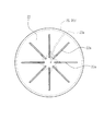
図5は本発明に係る電界磁界センサの一実施形態の構成を示す概念図、図6は送電鉄塔に電界磁界センサを縦方向に配置した状態を示す概念図、図7は図5のA−A断面図、図8はキャップの平面図、図9は磁界検出コイルの取付方向を変化させた電界磁界センサの構成を示した断面図である。
図中20は電界極、21は磁界コイル、22は樹脂製キャップ、23はステンレスパイプ、24は接続箱、25は同軸ケーブル、26はケーブルコネクタ、27は取り付けネジである。
そして、図5に示す様に、電界検出部である電界極20と磁界検出部である磁界コイル21を一体化して円筒状の検出部と成し、電界極20は検出部の筒状部外周面(外壁部材)に設けると共に、磁界コイル21は検出部の内部に装着している。
【0016】
本実施形態の電界磁界センサ6は、図5、7に示す様に、その電界極20が金属製略円筒状で、たとえばステンレスパイプ製で、磁束を遮蔽しないように縦にたとえば1箇所切断してある(切断箇所を符号20aで示す。)。電界極20をなすステンレスパイプ20dは、磁束を通す樹脂製のブラケット20bに固定してある。ブラケット20bの底部20cは、雨水で接続箱24との連結部材であるステンレスパイプ23が濡れないよう凹状に形成してある。
詳しくは、円筒状ケース20eの中間内部に磁界コイル21を装着すると共に、上下端部にブラケット20b、20fを固定し、円筒状ケース20eの外周に上下方向に所定幅の間隙(切断箇所20a)を有してステンレスパイプ20d(電界極20)を設けている。円筒状ケース20eの一部を貫通させると共に切断箇所20aの位置で電線をステンレスパイプ20dに接続し、モールド材で固定している。下端部のブラケット20bの凹状底部中央にブラケット20bに比して小径のステンレスパイプ23の上端を固定し、ステンレスパイプ23の下端を接続箱24に固定している。
【0017】
磁界検出コイル21は、商用周波から高周波の周波数特性とコイル出力電圧の大きさとを考慮し、ボビン21aに数百回電線21bを巻いて構成してある。
電力線3と電界磁界センサ6の関係において、磁界検出コイル21の装着方向は図5又は図9の様になり、電界磁界センサ6は直立状態で取り付けられる。
【0018】
図5、8に示す様に、電界極20(検出部)の頂部を覆うキャップ22は、磁束を遮蔽することがなく、また雨水が落ちやすくなるように円錐形状の樹脂製で形成してある。また、雨水で濡れても電界検出状態が変化しないように、たとえばステンレス製のワイヤ22aを縫うようにして外面に露出させて設けてある。詳しくは、キャップ22の傾斜面にワイヤ22aの露出部を放射状に複数配置すると共に、露出したワイヤ22aの両端部をキャップ22の傾斜面等を貫通させて裏面側で結線している。キャップ22に露出配置したワイヤ22aは検出部外周面に設けたステンレスパイプ20dとキャップ22下方の円筒状ケース20e内で電線接続し、ステンレスパイプ20dの他ワイヤ22aも電界極20の一部と成している。もちろんキャップ22の形状は、雨水が流れ落ちやすければ角錐等であってもよい。
【0019】
図5に示す様に、検出部と接続箱24を固定するステンレスパイプ23内に電界極20(ステンレスパイプ20dおよびワイヤ22a)と磁界検出コイル21の信号を流すための電線を収容し、ステンレスパイプ23の外装材としては、雨水を弾く材質、たとえばテフロン(登録商標)製の収縮チューブを装着して保護してある。
【0020】
上述の構造によると、キャップ22に設けたワイヤ22aは電界極20の一部となり、降雨時の雨水がキャップ22等に付着して水膜が発生しても、キャップ22表面に露出させて設けたワイヤ22aは水膜より導電性が高く、電界が通常集中する効果があるため、雨水に拘わらず電界極20はステンレスパイプ20dおよびワイヤ22aとなるため、雨水で検出部が濡れても電界検出強度が変わらない。
又、雨水で検出部や接続箱24が濡れても、検出部の底部(ブラケット20bの底部20c)が凹状であることにより、検出部の外周面(ステンレスパイプ20d)と連結部材のステンレスパイプ23は非接触、離隔しているため、鉄塔5や架台7へ検出した電界の微弱電流が漏洩しない。
したがって、降雨時であっても非降雨時と同様に雨水に影響されずに、送電電圧現象を検出する。
又、電界極20を検出部の外周面に設けたステンレスパイプ20dは、上下方向の切断箇所20aを設けてステンレスパイプ20dの一部を開口させているため、電力線3の電流による磁束を遮蔽することなく磁界検出コイル21で検出し得る。
【0021】
なお、図5の例において、電流を検出するコイル21を接続箱24内に収めて電界検出部と磁界検出部を別体化すると、送電線等と電界極20、磁界コイル21との距離と角度が違ってくるため、センサ出力を加算して得る零相電圧や零相電流等を正しく得ることができなくなる。
【0022】
【発明の効果】
本発明に係る電界磁界センサは以上説明してきたように、送電線等に非接触で電圧と電流が1個のセンサで測定でき、コスト的にも、設置スペース的にも有利なだけでなく、雨水で検出部が濡れても電界検出強度が変わらなかったり、検出した電界の微弱電流が鉄塔等に漏洩しないので、送電電圧現象を雨水の影響を受けることなく安定的に検出でき、又請求項2または3では磁界は磁束を遮蔽されることなく測定可能になるという効果がある。
【図面の簡単な説明】
【図1】電力設備の系統を示す架空送電線路の概念図である。
【図2】送電鉄塔に電界磁界センサを配置した状態を示す概念図である。
【図3】変電設備の架台に電界磁界センサを配置した状態を示す概念図である。
【図4】従来の電界磁界センサの構成を簡単に示した概念図である。
【図5】本発明に係る電界磁界センサの一実施形態の構成を示した断面図である。
【図6】送電鉄塔に電界磁界センサを縦方向に配置した状態を示す概念図である。
【図7】図5のA−A断面図である。
【図8】キャップの平面図である。
【図9】磁界検出コイルの取付方向を変化させた電界磁界センサの構成を示した断面図である。
【符号の説明】
1 供給側の電気所
2 変圧器の中性点抵抗器
3 三相架空送電線
4 需要側の電気所
5 送電鉄塔
6、6a、6b、6c 電界磁界センサ
7 送電用または変電用設備の架台
10 電界極
11 絶縁パイプ
12 磁界コイル
13 接続箱
14 同軸ケーブル
15 ケーブルコネクタ
16 取り付けネジ
20 電界極
20a 電界極をなすパイプの切断箇所
20b 電界極をなすパイプのブラケット
20c ブラケットの凹状の底部
20d 電界極をなすステンレスパイプ
20e 円筒状ケース
20f ブラケット
21 磁界コイル
21a ボビン
21b 電線
22 樹脂製キャップ
22a ワイヤ
23 ステンレスパイプ
24 接続箱
25 同軸ケーブル
26 ケーブルコネクタ
27 取り付けネジ[0001]
BACKGROUND OF THE INVENTION
The present invention relates to an electric field magnetic field sensor used for non-contact measurement of a transmission voltage and a transmission current phenomenon of a transmission / distribution electric wire line or a substation facility which is an outdoor power facility.
[0002]
[Prior art]
Transformers, resistance voltage dividers, capacitor voltage dividers, insulator voltage dividers, optical PTs, electric field detectors, etc. are used for voltage measurement during power transmission or failure of power facilities, and current transformers, Z Type CT, Hall CT, optical CT, magnetic field detector, etc. are used.
[0003]
Transformers, resistance voltage dividers, capacitor voltage dividers, and insulator voltage dividers used for voltage measurement must be designed in consideration of withstand voltage because they are directly connected to the power line. Although there is a characteristic with respect to the frequency, there is no frequency characteristic with respect to a high-frequency voltage caused by a voltage phenomenon at the time of failure, for example, a phenomenon such as a lightning failure. The optical PT has characteristics from a commercial frequency to a high frequency, but is difficult to install because it needs to pass a power line. The electric field detector obtains characteristics from commercial frequency to high frequency without contact with the power equipment, but the detection output tends to fluctuate due to the influence of rain.
[0004]
A current transformer used for current measurement needs to be connected to a power line and does not have high-frequency characteristics. The Z-type CT needs to pass a power line, needs to be grounded in consideration of withstand voltage, and does not have good high frequency characteristics. The hall CT has frequency characteristics but needs to be in contact with the underground line. The optical CT also needs to be attached to the power line although it has frequency characteristics. The magnetic field detector has no frequency contact with the power line and good frequency characteristics.
[0005]
A system that has been used in a conventional overhead power transmission line to measure a transmission voltage and a transmission current phenomenon in a contactless manner will be described (for example, see Patent Document 1).
Fig. 1 is a schematic diagram of an overhead transmission line. In the figure, 1 is a power station on the supply side (transmission equipment), 2 is a neutral point resistor of a transformer, 3 is a three-phase overhead transmission line, and 4 is electricity on the demand side. It is a place. FIG. 2 is a conceptual diagram showing a state in which an electric field magnetic field sensor is arranged on a power transmission tower. In FIG. 2, 5 is a steel tower, 3a, 3b, 3c of the overhead
[0006]
FIG. 3 is a conceptual diagram showing a state in which an electric field magnetic field sensor is arranged on a gantry of a substation equipment, and reference numeral 7 in the figure receives the gantry of the power transmission equipment or electricity for transmitting electricity to the overhead
[0007]
FIG. 4 is a conceptual diagram simply showing the configuration of a conventional electric field
[0008]
[Patent Document 1]
Japanese Examined Patent Publication No. 6-70665 [0009]
[Problems to be solved by the invention]
By the way, the conventional electric field
[0010]
This phenomenon is a major drawback that affects the performance of voltage measurement. The cause is that rainwater collects in the
However, for current measurement, since the
[0011]
In view of the above-mentioned conventional problems, the present invention can measure voltage and current with a single sensor without contact with a power transmission / distribution line, etc., and the measured voltage value is not affected by rainwater. An object of the present invention is to provide a supplementary electric field magnetic field sensor.
[0012]
[Means for Solving the Problems]
In order to achieve the above object , the electric field magnetic field sensor of the present invention is an electric field magnetic field sensor for non-contact measurement of a transmission voltage and a transmission current phenomenon of a transmission / distribution line or a substation, and includes an electric field detection unit and a magnetic field detection. And a connecting part for attaching the detecting part to the attaching part such as a steel tower, and a connecting member for connecting the detecting part and the connecting part apart from each other. In addition to covering with a cap, the bottom of the detection unit is formed in a concave shape to cover the upper end side of the connecting member .
[0013]
In order to achieve the above object, in the electric field magnetic field sensor having the above configuration, at least one wire-like conductor is exposed on the outer peripheral surface of the cap, and the conductor is connected to the electric field detection unit. It is characterized by becoming.
[0014]
In order to achieve the above object, in the electric field magnetic field sensor configured as described above, the outer wall of the detection unit is formed as an electric field detection unit, and the outer wall member is provided with a cut portion along the vertical direction. .
[0015]
DETAILED DESCRIPTION OF THE INVENTION
Embodiments of the present invention will be described below with reference to the drawings. In the following description, common parts are denoted by common reference numerals, and redundant description is omitted.
FIG. 5 is a conceptual diagram showing a configuration of an embodiment of an electric field magnetic field sensor according to the present invention, FIG. 6 is a conceptual diagram showing a state in which an electric field magnetic field sensor is arranged in a vertical direction on a power transmission tower, and FIG. A sectional view, FIG. 8 is a plan view of the cap, and FIG. 9 is a sectional view showing the configuration of the electric field magnetic field sensor in which the mounting direction of the magnetic field detection coil is changed.
In the figure, 20 is an electric field electrode, 21 is a magnetic field coil, 22 is a resin cap, 23 is a stainless steel pipe, 24 is a connection box, 25 is a coaxial cable, 26 is a cable connector, and 27 is a mounting screw.
Then, as shown in FIG. 5, the electric field electrode 20 as the electric field detection unit and the
[0016]
As shown in FIGS. 5 and 7, the electric field
Specifically, the
[0017]
The magnetic
In the relationship between the
[0018]
As shown in FIGS. 5 and 8, the
[0019]
As shown in FIG. 5, the electric field electrode 20 (stainless steel pipe 20d and
[0020]
According to the above-described structure, the
Even if the detection unit or the
Therefore, even when it is raining, the power transmission voltage phenomenon is detected without being affected by rainwater as in the case of non-rainfall.
Further, the stainless steel pipe 20d provided with the electric field electrode 20 on the outer peripheral surface of the detection unit is provided with a
[0021]
In the example of FIG. 5, if the
[0022]
【The invention's effect】
As described above, the electric field magnetic field sensor according to the present invention can measure the voltage and current with a single sensor without contact with a transmission line, etc., and is advantageous not only in terms of cost and installation space, or even not change the electric field detected intensity detection unit is wet with rain, because weak current of the detected electric field does not leak to the tower or the like, the transmission voltage phenomenon can stably detected without being affected by the rain water, also claim In 2 or 3, the magnetic field can be measured without shielding the magnetic flux.
[Brief description of the drawings]
FIG. 1 is a conceptual diagram of an overhead power transmission line showing a system of power equipment.
FIG. 2 is a conceptual diagram showing a state where an electric field magnetic field sensor is arranged on a power transmission tower.
FIG. 3 is a conceptual diagram showing a state in which an electric field magnetic field sensor is arranged on a gantry of a substation facility.
FIG. 4 is a conceptual diagram simply showing the configuration of a conventional electric field magnetic field sensor.
FIG. 5 is a cross-sectional view showing a configuration of an embodiment of an electric field magnetic field sensor according to the present invention.
FIG. 6 is a conceptual diagram showing a state where electric field magnetic field sensors are arranged in the vertical direction on a power transmission tower.
7 is a cross-sectional view taken along the line AA in FIG.
FIG. 8 is a plan view of the cap.
FIG. 9 is a cross-sectional view showing the configuration of an electric field magnetic field sensor in which the mounting direction of the magnetic field detection coil is changed.
[Explanation of symbols]
DESCRIPTION OF
Claims (3)
上記キャップの外周面にワイヤ状の導電体を少なくとも一ヶ所以上で露出させ、該導電体を上記電界検出部に接続してなることを特徴とする電界磁界センサ。 An electric field magnetic field sensor for non-contact measurement of transmission voltage and transmission current phenomenon of transmission / distribution lines and substation equipment, and it is attached to a detection part that integrates an electric field detection part and a magnetic field detection part, and a mounting location such as a steel tower And a connecting member that separates and connects the detection unit and the connection unit. The top of the detection unit is covered with a conical cap, and the bottom of the detection unit is formed in a concave shape. In the electric field magnetic field sensor covering the upper end side of the connecting member ,
An electric field magnetic field sensor comprising: a wire-like conductor exposed on at least one of the outer peripheral surfaces of the cap; and the conductor is connected to the electric field detection unit.
上記検出部の外壁を電界検出部と成すと共に、外壁部材に上下方向に沿って切断箇所を設けてなることを特徴とする電界磁界センサ。An electric field magnetic field sensor characterized in that an outer wall of the detection unit is formed as an electric field detection unit, and a cut portion is provided on the outer wall member along the vertical direction.
Priority Applications (1)
| Application Number | Priority Date | Filing Date | Title |
|---|---|---|---|
| JP2002258799A JP3765780B2 (en) | 2001-09-06 | 2002-09-04 | Electromagnetic field sensor |
Applications Claiming Priority (3)
| Application Number | Priority Date | Filing Date | Title |
|---|---|---|---|
| JP2001270507 | 2001-09-06 | ||
| JP2001-270507 | 2001-09-06 | ||
| JP2002258799A JP3765780B2 (en) | 2001-09-06 | 2002-09-04 | Electromagnetic field sensor |
Publications (2)
| Publication Number | Publication Date |
|---|---|
| JP2003156517A JP2003156517A (en) | 2003-05-30 |
| JP3765780B2 true JP3765780B2 (en) | 2006-04-12 |
Family
ID=26621772
Family Applications (1)
| Application Number | Title | Priority Date | Filing Date |
|---|---|---|---|
| JP2002258799A Expired - Lifetime JP3765780B2 (en) | 2001-09-06 | 2002-09-04 | Electromagnetic field sensor |
Country Status (1)
| Country | Link |
|---|---|
| JP (1) | JP3765780B2 (en) |
Cited By (1)
| Publication number | Priority date | Publication date | Assignee | Title |
|---|---|---|---|---|
| CN107330151A (en) * | 2017-05-31 | 2017-11-07 | 国网江苏省电力公司经济技术研究院 | A kind of extracting method of aperture electric polarization coefficient |
Families Citing this family (5)
| Publication number | Priority date | Publication date | Assignee | Title |
|---|---|---|---|---|
| SI24793B (en) * | 2014-09-24 | 2024-04-30 | E-Senzor D.O.O. | Wireless sensor detecting disconection of conductors in three-phase overground electricity line and a method relating to this |
| JP6532264B2 (en) * | 2015-03-31 | 2019-06-19 | 矢崎エナジーシステム株式会社 | Current detection device |
| WO2021248487A1 (en) * | 2020-06-12 | 2021-12-16 | 南京唐壹信息科技有限公司 | Smart power grid signal device with rainproof function |
| CN112526221B (en) * | 2020-10-26 | 2023-04-14 | 中国电子产品可靠性与环境试验研究所((工业和信息化部电子第五研究所)(中国赛宝实验室)) | Electromagnetic Field Composite Probes and Detection Systems |
| CN115327453B (en) * | 2022-08-10 | 2026-04-17 | 中国电子产品可靠性与环境试验研究所((工业和信息化部电子第五研究所)(中国赛宝实验室)) | Electromagnetic field composite probe |
-
2002
- 2002-09-04 JP JP2002258799A patent/JP3765780B2/en not_active Expired - Lifetime
Cited By (2)
| Publication number | Priority date | Publication date | Assignee | Title |
|---|---|---|---|---|
| CN107330151A (en) * | 2017-05-31 | 2017-11-07 | 国网江苏省电力公司经济技术研究院 | A kind of extracting method of aperture electric polarization coefficient |
| CN107330151B (en) * | 2017-05-31 | 2020-07-28 | 国网江苏省电力公司经济技术研究院 | Extraction method of small-hole electric polarization coefficient |
Also Published As
| Publication number | Publication date |
|---|---|
| JP2003156517A (en) | 2003-05-30 |
Similar Documents
| Publication | Publication Date | Title |
|---|---|---|
| US9689898B2 (en) | Medium or high voltage arrangement with cable connection terminal | |
| CN107078495A (en) | Cable terminations with integrated form monitoring arrangement | |
| US4700123A (en) | Power distribution systems and means for control thereof | |
| JP2000514191A (en) | Methods, apparatus and sensors for capacitively detecting electric and electric fields and their use | |
| JP3765780B2 (en) | Electromagnetic field sensor | |
| EP0851442B1 (en) | Lead-in insulator | |
| US5801526A (en) | Rate adjustable faulted circuit indicator module | |
| JP2004170172A (en) | Electric field magnetic field sensor | |
| US10444271B2 (en) | Device for monitoring an electrical conductor and electrical installaton comprising such a device | |
| JP3099186B2 (en) | Insulator type voltage sensor combined arrester | |
| KR102633469B1 (en) | Appratus of detecting a leakage current for porcelain insulator | |
| US7330033B2 (en) | Noncontact sensor | |
| KR101175738B1 (en) | Device for detecting leakage current of insulator | |
| CN217443474U (en) | Cable fault detection device | |
| JP2737056B2 (en) | Shielding method for physical quantity measurement system of movable high voltage body | |
| JP2932770B2 (en) | Distribution line monitoring device | |
| JPH0228461Y2 (en) | ||
| JPH09261813A (en) | Gas insulated switchgear | |
| JP2970375B2 (en) | Optical voltage measuring device | |
| US20260106054A1 (en) | Pole Part | |
| KR910001068Y1 (en) | Transformer for earth resistance measurement | |
| JPH01311283A (en) | Current monitoring instrument | |
| JPH07161248A (en) | Bus line voltage detecting device | |
| JP3455077B2 (en) | Directional ground fault detector | |
| JP2003282341A (en) | Zero-phase current detector |
Legal Events
| Date | Code | Title | Description |
|---|---|---|---|
| A977 | Report on retrieval |
Free format text: JAPANESE INTERMEDIATE CODE: A971007 Effective date: 20050518 |
|
| A131 | Notification of reasons for refusal |
Free format text: JAPANESE INTERMEDIATE CODE: A131 Effective date: 20050906 |
|
| A521 | Request for written amendment filed |
Free format text: JAPANESE INTERMEDIATE CODE: A523 Effective date: 20051031 |
|
| TRDD | Decision of grant or rejection written | ||
| A01 | Written decision to grant a patent or to grant a registration (utility model) |
Free format text: JAPANESE INTERMEDIATE CODE: A01 Effective date: 20060110 |
|
| A61 | First payment of annual fees (during grant procedure) |
Free format text: JAPANESE INTERMEDIATE CODE: A61 Effective date: 20060124 |
|
| R150 | Certificate of patent or registration of utility model |
Free format text: JAPANESE INTERMEDIATE CODE: R150 Ref document number: 3765780 Country of ref document: JP Free format text: JAPANESE INTERMEDIATE CODE: R150 |
|
| FPAY | Renewal fee payment (event date is renewal date of database) |
Free format text: PAYMENT UNTIL: 20100203 Year of fee payment: 4 |
|
| R250 | Receipt of annual fees |
Free format text: JAPANESE INTERMEDIATE CODE: R250 |
|
| FPAY | Renewal fee payment (event date is renewal date of database) |
Free format text: PAYMENT UNTIL: 20110203 Year of fee payment: 5 |
|
| R250 | Receipt of annual fees |
Free format text: JAPANESE INTERMEDIATE CODE: R250 |
|
| FPAY | Renewal fee payment (event date is renewal date of database) |
Free format text: PAYMENT UNTIL: 20120203 Year of fee payment: 6 |
|
| R250 | Receipt of annual fees |
Free format text: JAPANESE INTERMEDIATE CODE: R250 |
|
| FPAY | Renewal fee payment (event date is renewal date of database) |
Free format text: PAYMENT UNTIL: 20130203 Year of fee payment: 7 |
|
| R250 | Receipt of annual fees |
Free format text: JAPANESE INTERMEDIATE CODE: R250 |
|
| FPAY | Renewal fee payment (event date is renewal date of database) |
Free format text: PAYMENT UNTIL: 20140203 Year of fee payment: 8 |
|
| R250 | Receipt of annual fees |
Free format text: JAPANESE INTERMEDIATE CODE: R250 |
|
| R250 | Receipt of annual fees |
Free format text: JAPANESE INTERMEDIATE CODE: R250 |
|
| R250 | Receipt of annual fees |
Free format text: JAPANESE INTERMEDIATE CODE: R250 |
|
| R250 | Receipt of annual fees |
Free format text: JAPANESE INTERMEDIATE CODE: R250 |
|
| R250 | Receipt of annual fees |
Free format text: JAPANESE INTERMEDIATE CODE: R250 |
|
| R250 | Receipt of annual fees |
Free format text: JAPANESE INTERMEDIATE CODE: R250 |
|
| R250 | Receipt of annual fees |
Free format text: JAPANESE INTERMEDIATE CODE: R250 |
|
| R250 | Receipt of annual fees |
Free format text: JAPANESE INTERMEDIATE CODE: R250 |
|
| R250 | Receipt of annual fees |
Free format text: JAPANESE INTERMEDIATE CODE: R250 |
|
| R250 | Receipt of annual fees |
Free format text: JAPANESE INTERMEDIATE CODE: R250 |
|
| EXPY | Cancellation because of completion of term |