JP3774532B2 - Storage method when turbine equipment of thermal power plant is stopped - Google Patents
Storage method when turbine equipment of thermal power plant is stopped Download PDFInfo
- Publication number
- JP3774532B2 JP3774532B2 JP05274997A JP5274997A JP3774532B2 JP 3774532 B2 JP3774532 B2 JP 3774532B2 JP 05274997 A JP05274997 A JP 05274997A JP 5274997 A JP5274997 A JP 5274997A JP 3774532 B2 JP3774532 B2 JP 3774532B2
- Authority
- JP
- Japan
- Prior art keywords
- turbine
- pressure
- steam
- power plant
- thermal power
- Prior art date
- Legal status (The legal status is an assumption and is not a legal conclusion. Google has not performed a legal analysis and makes no representation as to the accuracy of the status listed.)
- Expired - Lifetime
Links
Images


Landscapes
- Control Of Turbines (AREA)
Description
【0001】
【発明の属する技術分野】
本発明は火力発電プラントのタービンの使用方法に係わり、特にタービンを構成する部材の長期にわたる信頼性向上に効果のある、プラントのタービン機器停止時の保管方法及びタービン機器に関する。
【0002】
【従来の技術】
燃料の燃焼により発生させた蒸気を用いてタービンを回転させて動力を得る火力プラントの給水系を構成する機器部材の腐食を防止する方法として、揮発性物質処理(AVT:All Volatile Treatment),酸素処理(CWT:Combined Water Treatment),リン酸塩処理(Coodinated Phosphate Treatment)の三つの水処理方法が知られている。
【0003】
このうち、揮発性物質処理(以下、AVTと称する)は、蒸気発生装置の入り口側において、復水・給水系統から供給された給水を採取し、給水のpHおよび溶存酸素濃度を測定する。そして、採取した給水のpHが9.0〜9.6,溶存酸素濃度が7ppb 以下となるように、低圧給水加熱器の入り口側からアンモニアもしくはヒドラジンを注入するというものである。
【0004】
一方、酸素処理(以下CWTと称する)は、蒸気発生装置の入り口側において、復水・給水系統から供給された給水を採取し、そのpHが8.0〜9.0,溶存酸素が20〜200ppb になるように、低圧給水加熱器の入り口側からアンモニアを注入する。また、復水昇圧ポンプの入り口側および給水ポンプの入り口側から酸素を注入するというものである。
【0005】
また、リン酸塩処理はpH調整剤として苛性ソーダなどを用い、硬度除去剤としてリン酸ソーダなどを用いるもので、pHの調整範囲は一般に高く、10.5〜11.8 程度である。この方式は、圧力30kg/cm2 級以下のボイラによく使用されている。pHが高いので鋼材の防食に適し酸素の侵入にも強く、また復水器から海水がリークしたときにもボイラ水のpHの低下を防ぎ腐食を防止する。しかしながら、熱負荷の大きいところ、あるいはスケールなどの付着している部分では苛性ソーダの濃縮が起こり腐食を引き起こすので、中圧,高圧ボイラでは使われていない。
【0006】
これらの水処理法は、いずれも火力プラントの給水系の防食を目的とした技術であるが、上述した三つの水処理としては、たとえば、特開昭60−100688号公報,特開平4−128395 号公報に記載のものが知られている。また、上述した三つの水処理のpHおよび溶存酸素の範囲としては、「JIS,日本規格協会,1989年発行,ボイラの給水およびボイラ水の水質(JIS B 8223)」に記載されている。
【0007】
【発明が解決しようとする課題】
近年の火力プラントにおける水処理は、前述した三つの水処理のうち、CWTの水処理法が主流になりつつある。前述したAVTの水処理においては、蒸気発生装置に給水される復水のpHを9.0〜9.6(アルカリ性)としているので、鉄の溶出抑制に対して有効であり、蒸気発生装置の蒸発管等の信頼性を保つことができるが、プラントによっては、蒸気発生装置の蒸発管の内面にスケールが生成し、蒸気発生装置の差圧を著しく上昇させることがわかってきている。これに対し、CWTの水処理においては、蒸気発生装置に給水される復水に注入された酸素により、蒸気発生装置の蒸発管の内面にヘマタイトの粒子を生成させ、緻密で平滑な皮膜表面を形成し、スケール(腐食)を防止し蒸気発生装置の差圧上昇を抑制することができるからである。
【0008】
しかし、CWTの水処理においては、温度が低い場合、前述したヘマタイトの粒子の生成が不十分となり、機器を構成する鉄鋼材等から鉄の溶出を増加させるという問題点がある。特に、低圧タービンおよび給水ポンプ駆動タービンにおいては、駆動源である蒸気が凝縮する湿り蒸気領域にあるので、温度が低く、前述したヘマタイトの粒子の生成が不十分となる。これにより、タービンを構成する材料の腐食を加速し、タービンの信頼性を低下させる恐れがある。
【0009】
また、一方でタービンの動翼の付け根のdovetail部にはしばしば、すき間腐食や応力腐食割れを生じタービン翼の信頼性を損なうこともある。この問題は、低圧タービンのローターの信頼性、寿命を左右する要因となっており、腐食や固形物の付着を防ぐために、蒸気中のNaClなどの不純物濃度の管理が行われている。これは、dovetail部のすき間内部とその周辺に酸素濃淡電池を生じ、すき間内部にCl- などのハロゲンイオンが濃縮、pHが低下し材料が活性溶解を起こすものである。この酸素濃淡電池が形成されるためには、dovetail部のすき間周辺に溶存酸素濃度の大きな水溶液が必要で、この溶存酸素の上昇は、プラント停止時の減圧時に、蒸気が冷却してできた凝縮水中に、タービン外部から空気が混入するためと推定されている。
【0010】
ところで、蒸気タービン機器を停止した場合には、タービン温度の低下に伴いタービン機器内の気体が収縮することにより、圧力が大気圧に比べ小さくなった状態で保管されていた。従って、タービンケーシング内のラビリンスなどの軸受けシール部や復水器などからの外気の混入が不可避で、従って凝縮水中の溶存酸素濃度上昇を招き、これがすき間腐食や応力腐食割れ発生の原因となっていると考えられる。
【0011】
このようなすき間腐食や応力腐食割れには、従来の水質管理方法だけでは対処不可能であった。
【0012】
本発明の目的は、火力プラントのタービン機器停止時でのすき間腐食や孔食を防止し、プラントを構成する機器、特にタービン動翼のdovetail部に対して、効果的かつ高寿命化を計った信頼性の高い保管・停止方法を提供することにある。
【0013】
【課題を解決するための手段】
上記目的を達成するため、本発明の第1の発明によれば、燃料の燃焼により発生させた熱エネルギーを用いて水を蒸気とし、その蒸気によりタービンを回転させてエネルギーを得る火力プラントのタービン機器停止時の保管方法において、タービンケーシング内を非酸化性雰囲気とし、かつ該雰囲気の圧力を大気圧に比べて大きくすることを特徴とする火力プラントのタービン機器停止時の保管方法が提供される。タービンケーシングとは、タービンブレード,タービンロータシャフトを外界と遮断するように納める容器のことである。非酸化性雰囲気とは、最も一般的には不活性ガスであるアルゴン、窒素等を用いることができるが、酸素を含まないガスであれば良い。
【0014】
上記構成により、タービン機器停止時のタービン中の凝縮水の溶存酸素濃度の増加を防止することができる。すなわち、タービン機器停止時においても、タービンブレードとタービンロータシャフトをつなぐダブティル(dovetail)部等に溶存酸素による隙間腐食が発生せず、信頼性の高い火力プラントのタービン機器を提供することができる。
【0015】
第1の発明のタービン機器が、高圧タービン,中圧タービン,低圧タービンおよび給水ポンプ駆動タービンのいずれかに適用することができる。
【0016】
第1の発明の非酸化性雰囲気ガスの注入方法が、タービン停止時の温度低下に伴うタービンケーシング内部の圧力の低下に対応して、前記ガスを注入することが好ましい。タービン停止時には、タービン中の気体が収縮し、ケーシング中の圧力が大気圧に比べて低下する。その圧力低下の程度にあわせて非酸化性ガスの注入を行い、ケーシング中の圧力が常に大気圧に比べて大きい値となるように調整することにより、大気中の酸素がケーシング中に混入することを防止できる。従って、タービン中の凝縮水の溶存酸素濃度の増加を防止でき、隙間腐食を抑制できる。タービンが常温に戻った後はケーシング中の圧力の低下が停止するので、このような必要はなくなるが、タービン停止から常温に戻るには、タービンの大きさにもよるが、数日程度はかかるため、上記方法は効果的である。
【0017】
第1の発明の非酸化性雰囲気ガスを、タービン静翼に設けた空気噴出孔からタービンケーシング内に注入しても良い。
【0018】
第1の発明の非酸化性雰囲気ガスを、高圧あるいは低圧タービンの入り口側あるいは復水昇圧ポンプ及び給水ポンプの入り口側から注入しても良い。
【0019】
第1の発明において、タービンケーシング中の凝縮水中にインヒビタを添加しても良い。
【0020】
また、上記目的を達成するため、本発明の第2の発明によれば、燃料の燃焼により発生させた熱エネルギーを用いて水を蒸気とし、その蒸気によりタービンを回転させてエネルギーを得る火力プラントのタービン機器において、タービン停止時に、タービンケーシング内へ非酸化性雰囲気ガスを注入する機構を有することを特徴とする火力プラントのタービン機器が提供される。
【0021】
第2の発明において、前記非酸化性雰囲気ガスの該タービンケーシング内への注入量を、タービンケーシング内の圧力計の指示に基づいて、制御する機構を有することが好ましい。ケーシング内の圧力計の指示に基づいて、手動で非酸化性ガスの注入量を制御しても良いが、例えば圧力計の指示を電気的信号として出力し、その出力に応じて、マイクロコンピュータにより非酸化性ガスのボンベのバルブの開閉量を制御するような機構を用いるのが最も好ましい。前述したように、タービンは停止から常温に戻るには数日間かかるため、その間、人間が注入量を連続的に制御するのは難しいからである。
【0022】
上記構成により、タービン停止後の、タービンケーシング内の圧力を長期間一定に保つことができる。
【0023】
【発明の実施の形態】
(実施例1)
以下、本発明の実施例を図面を用いて説明する。
【0024】
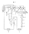
図1は本発明の実施例である火力プラントを示す系統図である。まず、火力プラントの構成を説明する。火力プラントは大別すると蒸気発生装置11を上流側とし復水器1を下流側とする蒸気系統と、復水器1を上流側とし蒸気発生装置 11を下流側とする復水・給水系統とからなっている。
【0025】
このうち、蒸気系統は、蒸気発生装置11で発生した蒸気を駆動源とする高圧蒸気タービン12と、高圧蒸気タービン12の排出蒸気を蒸気発生装置11で加熱し得られた再熱蒸気を駆動源とする中圧蒸気タービン13と、中圧蒸気タービン13の排出蒸気を駆動源とする低圧蒸気タービン14とを備えている。
【0026】
蒸気発生装置11で発生した蒸気は、高圧蒸気配管を介して高圧蒸気タービン12に供給されタービンを駆動する。高圧蒸気タービン12駆動後の蒸気は、低圧蒸気配管を介して低圧蒸気タービン14に供給されタービンを駆動する。そして、低圧蒸気タービン14駆動後の蒸気は、復水器1に排出され凝縮せしめられる。
【0027】
また、上記の系統は、後述する給水ポンプを駆動する給水ポンプ駆動蒸気タービン15を備えており、給水ポンプ駆動蒸気タービン15には、高圧蒸気配管から分岐した分岐管を介して高圧蒸気タービン12に供給される蒸気の一部、もしくは中圧蒸気タービン13の抽気が供給されタービンを駆動する。そして、給水ポンプ駆動蒸気タービン15駆動後の蒸気は、排出管を介して復水器1に排出され、前述同様に凝縮せしめられる。
【0028】
一方、復水・給水系統は、蒸気タービン(低圧蒸気タービン14,給水ポンプ駆動蒸気タービン15)から排出された蒸気を復水器1で凝縮し、得られた蒸気を脱気器8に供給する復水系統と、脱気器8で脱気された復水を蒸気発生装置 11に供給する給水系統に区分される。
【0029】
このうち、復水系統は、復水器1で凝縮し得られた復水を送水する復水ポンプ2と、復水ポンプ2からグランドコンデンサ3を介して送水された復水中に含まれる鉄酸化物等の腐食生成物を除去する復水濾過器4と、復水中に含まれるCl-イオン等を除去する復水脱塩装置5と復水濾過器4および復水脱塩装置5により復水中に含まれる腐食生成物および不純物イオンが除去された復水を低圧給水加熱器7を介して脱気器8に送水する復水昇圧ポンプ6とを備えている。
【0030】
また、給水系統は、脱気器8により脱塩された復水を高圧給水加熱器10を介して蒸気発生装置11に給水する給水ポンプ9を備えている。なお、給水ポンプ9は駆動源として、前述した給水ポンプ駆動蒸気タービン15を備えている。
【0031】
復水器1で凝縮された復水は、復水ポンプ2からグランドコンデンサ3を介して復水濾過器4に送水され、復水中に含まれる鉄酸化物等の腐食生成物を除去する。次に復水は、復水脱塩装置5に送水され、復水中に含まれる不純物イオンを除去する。このように、復水中に含まれる腐食生成物および不純物イオンが除去された後、復水昇圧ポンプ6によって昇圧され、途中低圧給水加熱器7より加熱され、脱気器8に送水される。脱気器8は、送水された復水を脱気する。そして、脱気器8によって脱気された復水は、給水ポンプ9によって送水され、途中高圧加熱器により加熱され、蒸気発生装置11に給水される。
【0032】
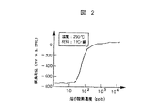
まず予備検討として、すき間外部の凝縮水中の溶存酸素濃度をどれくらいに下げればよいかについて、電位測定を実施した。すなわち、290℃において、環境水中の溶存酸素濃度を種々に変化させ、12Cr鋼試験片の電位を測定した。その結果を図2に示す。すき間腐食の進行は、すき間内外の酸素濃度差による電位差による局部電池によって進行するので、すき間腐食を防止するには、このすき間内外の電位差を小さくすればよいことになる。すき間内部の酸素は金属の腐食によって消費され、ほぼ数ppb 以下になっているものと考えられるから、すき間外部の溶存酸素濃度は、この数ppb の溶存酸素濃度の腐食電位から大きく異ならない値になっていればよい。図2からこの値を読みとると、すき間内外の電位差は20ppb 以下ぐらいに、したがって、すき間外部の凝縮水中の溶存酸素濃度は、20ppb 以下ぐらいになっていればよいことが分かる。
【0033】
次に、この火力プラントの保管停止方法について説明する。
【0034】
電力の出力需要の小さい夜間時に、プラントを停止すべく、出力を徐々に低下させる。それに伴って、蒸気温度も徐々に低下する。この火力プラントの高圧,中圧,低圧タービン、および給水ポンプ駆動タービンの停止時に不活性ガスとして、窒素を注入するために、以下のような手段を講じる。すなわち、プラント停止後高圧タービンとボイラー間、低圧タービンと復水器間のバルブを閉じることにより、タービン部のみをアイソレーションし、他系統から孤立させる。タービン停止後の時間の経過とともに、このタービン内の蒸気温度が下がって圧力が外気圧より低くなった時点で、各タービンに接続した窒素注入ラインのバルブを開く。不活性ガスの圧力は、最初は、2〜3気圧に保ち、温度が低下し、大気圧に比べて十分タービン内の蒸気圧が下がった温度、たとえば90℃以下になった時点で窒素の圧力を下げ、かつ外気より数%高く保ち、タービン内を外気に対して加圧条件にする。この停止保管時のタービン中の凝縮水中の溶存酸素濃度をサンプリングラインから凝縮水を採取して計測したところ数10ppb 以下であった。また、これと比較のために、プラント停止後従来法である真空保管をして、凝縮水中の溶存酸素濃度を連続測定した。その結果、図3に示すようにデイリー・スタート・ストップの場合、凝縮水中の溶存酸素は、タービン停止後数時間は数10ppb と低い値を示すが、その後ゆるやかに上昇し、タービン再起動前には、1〜2ppm と比較的高い値になった。
【0035】
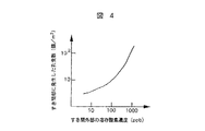
一方、dovetail部に発生する孔食と、dovetail外部の溶存酸素濃度との関係を求めた。すなわち、dovetail部を模擬したすき間試験片をタービンと同じ温度で1〜2日蒸気に暴露し、その後デイリー・スタート・ストップを模擬して、半日間冷却し凝縮中の溶存酸素レベルを種々の濃度に保った後再び昇温するという実験を行った。この実験を2000h行って、孔食発生数および、孔食深さを調べ、孔食深さから孔食の進行速度を計算した。その結果、図4や図5に示すように、dovetail部すき間周辺の溶存酸素濃度と、発生する孔食数、ならびに孔食の進行速度の間には、比例関係があることが分かった。従って、これらの結果から、本実施例のように、dovetail部に接触する蒸気の凝縮水中の溶存酸素濃度を下げることによって、すき間内外の酸素濃淡電池の形成に起因する、dovetail部内のすき間腐食が抑制される。
【0036】
(実施例2)
火力プラントのデイリー・スタート・ストップのもう一つの実施例を示す。ここでは実施例1で示した、不活性ガスに併用してインヒビタを使用する。すなわち、火力プラントの高圧,中圧,低圧タービン、および給水ポンプ駆動タービンの停止時に不活性ガスとして、アルゴンを実施例1と同様の方法で注入した。すなわち、実施例1と同様にパルブを閉めることによってタービン部分を、復水系や給水系からアイソレーションして孤立させた後、不活性ガスをタービン静翼の空気噴出孔から注入した。圧力は、最初は、2〜3気圧に保ち、温度が低下し、ケーシング内の圧力が外気圧よりも小さくなった時点で、不活性ガスの圧力を外気より数%高く保ちその後にガス注入をストップする。次に、タービン入り口から、薬注ポンプで、ヒドラジンを注入する。この停止保管時のタービン中の凝縮水中の溶存酸素濃度をサンプリングラインから凝縮水を採取して計測したところ数10ppb 以下であった。
【0037】
従って、以上の結果と、図4,図5の結果をあわせて考えると、この定期点検時の不活性ガス注入によりプラント運転中のdovetail部内のすき間内外の酸素濃淡に起因するdovetail部の腐食は大幅に低減できる。
【0038】
【発明の効果】
本発明によれば、タービン機器停止時においても、タービンブレードとタービンロータシャフトをつなぐダブテイル(dovetail)部等に溶存酸素による隙間腐食が発生せず、信頼性の高い火力プラントのタービン機器を提供することができる。
【図面の簡単な説明】
【図1】本発明の一実施例を示す火力プラントの系統図。
【図2】溶存酸素濃度と腐食電位の関係を示す図。
【図3】タービン停止後の溶存酸素濃度とタービン内温度の変化を示す図。
【図4】隙間外部の溶存酸素濃度と隙間部に発生した孔食数との関係を示す図。
【図5】隙間外部の溶存酸素濃度と隙間部に発生した孔食の進行速度との関係を示す図。
【符号の説明】
1…復水器、2…復水ポンプ、3…グランドコンデンサ、4…復水濾過器、5…復水脱塩装置、6…復水昇圧ポンプ、7…低圧給水加熱器、8…脱気器、9…給水ポンプ、10…高圧給水加熱器、11…蒸気発生装置、12…高圧蒸気タービン、13…中圧蒸気タービン、14…低圧蒸気タービン、15…給水ポンプ駆動蒸気タービン、16…差圧計、17…窒素注入ライン。[0001]
BACKGROUND OF THE INVENTION
The present invention relates to a method of using a turbine of a thermal power plant, and more particularly to a storage method and turbine equipment when the turbine equipment of the plant is stopped, which is effective for improving the reliability of the members constituting the turbine over a long period of time.
[0002]
[Prior art]
Volatile treatment (AVT), oxygen as a method to prevent corrosion of equipment components constituting the water supply system of a thermal power plant that uses steam generated by fuel combustion to rotate the turbine to obtain power Three water treatment methods are known: treatment (CWT: Combined Water Treatment) and phosphate treatment (Coodinated Phosphate Treatment).
[0003]
Among these, in the volatile substance treatment (hereinafter referred to as AVT), the feed water supplied from the condensate / feed water system is collected on the inlet side of the steam generator, and the pH of the feed water and the dissolved oxygen concentration are measured. Then, ammonia or hydrazine is injected from the inlet side of the low-pressure feed water heater so that the pH of the collected feed water is 9.0 to 9.6, and the dissolved oxygen concentration is 7 ppb or less.
[0004]
On the other hand, oxygen treatment (hereinafter referred to as CWT) collects feed water supplied from the condensate / feed water system at the inlet side of the steam generator, and has a pH of 8.0 to 9.0 and dissolved oxygen of 20 to 20%. Ammonia is injected from the inlet side of the low-pressure feed water heater so that the pressure becomes 200 ppb. In addition, oxygen is injected from the inlet side of the condensate booster pump and the inlet side of the feed water pump.
[0005]
Phosphate treatment uses caustic soda as a pH adjuster and sodium phosphate as a hardness remover, and the pH adjustment range is generally high, about 10.5 to 11.8. This system is often used for boilers with a pressure of 30 kg / cm 2 or less. Since the pH is high, it is suitable for corrosion prevention of steel materials and is strong against oxygen intrusion. Also, when seawater leaks from the condenser, the pH of boiler water is prevented from lowering and corrosion is prevented. However, caustic soda concentrates at places where the heat load is large, or where the scales are attached, causing corrosion and is not used in medium and high pressure boilers.
[0006]
These water treatment methods are all techniques for the purpose of preventing corrosion of the water supply system of a thermal power plant. Examples of the three water treatments described above include, for example, JP-A-60-100688 and JP-A-4-128395. The ones described in the publication No. are known. Further, the ranges of pH and dissolved oxygen of the three water treatments described above are described in “JIS, Japanese Standards Association, 1989, Boiler Supply Water and Boiler Water Quality (JIS B 8223)”.
[0007]
[Problems to be solved by the invention]
Among the three water treatments mentioned above, the CWT water treatment method is becoming mainstream in recent water treatment in thermal power plants. In the above-described AVT water treatment, the pH of the condensate supplied to the steam generator is set to 9.0 to 9.6 (alkaline), which is effective in suppressing iron elution. Although it is possible to maintain the reliability of the evaporation pipe or the like, it has been found that, depending on the plant, a scale is generated on the inner surface of the evaporation pipe of the steam generator, and the pressure difference of the steam generator is significantly increased. In contrast, in CWT water treatment, oxygen injected into the condensate supplied to the steam generator generates hematite particles on the inner surface of the steam generator's evaporation pipe, resulting in a dense and smooth coating surface. This is because it can be formed, scale (corrosion) can be prevented, and an increase in the differential pressure of the steam generator can be suppressed.
[0008]
However, in the water treatment of CWT, when the temperature is low, the above-described production of hematite particles becomes insufficient, and there is a problem in that iron elution is increased from the steel material or the like constituting the device. In particular, in the low-pressure turbine and the feed water pump drive turbine, the temperature is low and the generation of the aforementioned hematite particles becomes insufficient because the drive source steam is in the wet steam region where the steam is condensed. Thereby, corrosion of the material which comprises a turbine is accelerated, and there exists a possibility of reducing the reliability of a turbine.
[0009]
On the other hand, crevice corrosion and stress corrosion cracking often occur in the dovetail portion at the base of the turbine rotor blade, thereby impairing the reliability of the turbine blade. This problem is a factor that affects the reliability and life of the rotor of the low-pressure turbine, and the concentration of impurities such as NaCl in the steam is managed in order to prevent corrosion and solid matter adhesion. This results in oxygen concentration cell in and around the internal clearance of the dovetail portions, Cl inside gap - a halogen ion such as enrichment, reduces the pH material is intended to cause active dissolution. In order to form this oxygen concentration cell, an aqueous solution with a high dissolved oxygen concentration is required around the gap in the dovetail part, and this increase in dissolved oxygen is caused by the condensation of the steam that was cooled when the plant was shut down. It is estimated that air enters the water from outside the turbine.
[0010]
By the way, when the steam turbine equipment is stopped, the gas in the turbine equipment contracts as the turbine temperature decreases, so that it is stored in a state where the pressure is smaller than the atmospheric pressure. Therefore, it is inevitable to mix outside air from bearing seals such as labyrinths in the turbine casing and condensers, thus leading to an increase in dissolved oxygen concentration in condensed water, which causes crevice corrosion and stress corrosion cracking. It is thought that there is.
[0011]
Such crevice corrosion and stress corrosion cracking cannot be dealt with only by the conventional water quality management method.
[0012]
An object of the present invention is to prevent crevice corrosion and pitting corrosion when turbine equipment of a thermal power plant is stopped, and to achieve an effective and long life for the equipment constituting the plant, particularly the dovetail portion of the turbine blade. It is to provide a highly reliable storage / stop method.
[0013]
[Means for Solving the Problems]
In order to achieve the above object, according to the first aspect of the present invention, a turbine of a thermal power plant that obtains energy by turning water into steam using thermal energy generated by combustion of fuel and rotating the turbine with the steam. In the storage method at the time of equipment stop, a storage method at the time of turbine equipment stop of a thermal power plant is provided, wherein the inside of the turbine casing is made into a non-oxidizing atmosphere and the pressure of the atmosphere is made larger than the atmospheric pressure. . The turbine casing is a container that houses a turbine blade and a turbine rotor shaft so as to be isolated from the outside. As the non-oxidizing atmosphere, argon, nitrogen, or the like that is an inert gas can be used most generally, but any gas that does not contain oxygen may be used.
[0014]
By the said structure, the increase in the dissolved oxygen concentration of the condensed water in the turbine at the time of a turbine apparatus stop can be prevented. That is, even when the turbine equipment is stopped, crevice corrosion due to dissolved oxygen does not occur in the dovetail portion connecting the turbine blade and the turbine rotor shaft, and the turbine equipment of a highly reliable thermal power plant can be provided.
[0015]
The turbine equipment of the first invention can be applied to any of a high pressure turbine, an intermediate pressure turbine, a low pressure turbine, and a feed water pump drive turbine.
[0016]
It is preferable that the non-oxidizing atmosphere gas injection method according to the first aspect of the invention injects the gas in response to a decrease in pressure inside the turbine casing accompanying a temperature decrease when the turbine is stopped. When the turbine is stopped, the gas in the turbine contracts and the pressure in the casing decreases compared to the atmospheric pressure. Injecting non-oxidizing gas in accordance with the degree of pressure drop and adjusting the pressure in the casing to always be larger than the atmospheric pressure, so that oxygen in the atmosphere is mixed into the casing. Can be prevented. Therefore, an increase in the dissolved oxygen concentration of the condensed water in the turbine can be prevented, and crevice corrosion can be suppressed. Since the pressure drop in the casing stops after the turbine returns to normal temperature, this need is eliminated, but it takes several days to return to normal temperature after the turbine stops, depending on the size of the turbine. Therefore, the above method is effective.
[0017]
The non-oxidizing atmosphere gas of the first invention may be injected into the turbine casing from an air ejection hole provided in the turbine stationary blade.
[0018]
The non-oxidizing atmospheric gas of the first invention may be injected from the inlet side of the high-pressure or low-pressure turbine or from the inlet side of the condensate booster pump and the feed water pump.
[0019]
In the first invention, an inhibitor may be added to the condensed water in the turbine casing.
[0020]
In order to achieve the above object, according to the second aspect of the present invention, a thermal power plant that uses water as steam by using heat energy generated by fuel combustion, and rotates the turbine by the steam to obtain energy. The turbine equipment of the thermal power plant having a mechanism for injecting a non-oxidizing atmosphere gas into the turbine casing when the turbine is stopped is provided.
[0021]
In a second aspect of the present invention, it is preferable to have a mechanism for controlling the injection amount of the non-oxidizing atmospheric gas into the turbine casing based on an instruction from a pressure gauge in the turbine casing. The injection amount of the non-oxidizing gas may be controlled manually based on the instruction of the pressure gauge in the casing. For example, the instruction of the pressure gauge is output as an electrical signal, and the microcomputer outputs a signal according to the output. It is most preferable to use a mechanism that controls the opening / closing amount of a non-oxidizing gas cylinder. As described above, since it takes several days for the turbine to return to normal temperature from the stop, it is difficult for a human to continuously control the injection amount during that time.
[0022]
With the above configuration, the pressure in the turbine casing after the turbine is stopped can be kept constant for a long time.
[0023]
DETAILED DESCRIPTION OF THE INVENTION
Example 1
Embodiments of the present invention will be described below with reference to the drawings.
[0024]
FIG. 1 is a system diagram showing a thermal power plant that is an embodiment of the present invention. First, the configuration of the thermal power plant will be described. The thermal power plant is roughly divided into a steam system having the steam generator 11 as an upstream side and the condenser 1 as a downstream side, and a condensate / water supply system having the condenser 1 as an upstream side and the steam generator 11 as a downstream side. It is made up of.
[0025]
Among them, the steam system is a high-
[0026]
The steam generated by the steam generator 11 is supplied to the high-
[0027]
Further, the above system includes a feed water pump
[0028]
On the other hand, the condensate / feed water system condenses the steam discharged from the steam turbine (low
[0029]
Of these, the condensate system is composed of a
[0030]
The water supply system also includes a water supply pump 9 that supplies the condensate desalted by the deaerator 8 to the steam generator 11 via the high-
[0031]
The condensate condensed in the condenser 1 is sent from the
[0032]
First, as a preliminary study, potential measurement was performed to determine how much the dissolved oxygen concentration in the condensed water outside the gap should be lowered. That is, at 290 ° C., the dissolved oxygen concentration in the environmental water was variously changed, and the potential of the 12Cr steel specimen was measured. The result is shown in FIG. The progress of crevice corrosion proceeds by a local battery due to a potential difference caused by a difference in oxygen concentration inside and outside the gap. Therefore, in order to prevent crevice corrosion, the potential difference inside and outside the gap should be reduced. It is considered that oxygen inside the gap is consumed by the corrosion of the metal, and it is considered that it is almost several ppb or less, so the dissolved oxygen concentration outside the gap does not differ greatly from the corrosion potential of this several ppb dissolved oxygen concentration. It only has to be. Reading this value from FIG. 2, it can be seen that the potential difference inside and outside the gap should be about 20 ppb or less, and therefore the dissolved oxygen concentration in the condensed water outside the gap should be about 20 ppb or less.
[0033]
Next, a storage stop method for this thermal power plant will be described.
[0034]
The output is gradually reduced to stop the plant at night when the output demand for power is small. Along with this, the steam temperature gradually decreases. In order to inject nitrogen as an inert gas when the high-pressure, medium-pressure, low-pressure turbine, and feed water pump drive turbine of this thermal power plant are stopped, the following measures are taken. That is, after shutting down the plant, by closing the valves between the high-pressure turbine and the boiler and between the low-pressure turbine and the condenser, only the turbine section is isolated and isolated from other systems. With the passage of time after the turbine stops, when the steam temperature in the turbine decreases and the pressure becomes lower than the external pressure, the valve of the nitrogen injection line connected to each turbine is opened. The pressure of the inert gas is initially maintained at 2 to 3 atm, the temperature is lowered, and the temperature of the vapor pressure in the turbine is sufficiently lower than the atmospheric pressure. And keep the pressure higher than the outside air by several percent to make the inside of the turbine pressurize against the outside air. The concentration of dissolved oxygen in the condensed water in the turbine at the time of stop storage was measured by collecting the condensed water from the sampling line and found it to be several tens of ppb or less. In addition, for comparison with this, after the plant was shut down, the conventional method of vacuum storage was performed, and the dissolved oxygen concentration in the condensed water was continuously measured. As a result, in the case of daily start / stop as shown in FIG. 3, the dissolved oxygen in the condensed water shows a low value of several tens of ppb for several hours after the turbine shuts down, but then rises slowly before the turbine restarts. Was a relatively high value of 1 to 2 ppm.
[0035]
On the other hand, the relationship between the pitting corrosion generated in the dovetail part and the dissolved oxygen concentration outside the dovetail was obtained. That is, a gap test piece simulating the dovetail part is exposed to steam at the same temperature as the turbine for 1-2 days, and then simulated for daily start / stop, cooled for half a day, and the dissolved oxygen level during condensation is varied. An experiment was conducted in which the temperature was increased again after the temperature was maintained. This experiment was conducted for 2000 hours, the number of pitting corrosion occurrences and the pitting corrosion depths were examined, and the progress rate of pitting corrosion was calculated from the pitting corrosion depth. As a result, as shown in FIG. 4 and FIG. 5, it was found that there is a proportional relationship between the dissolved oxygen concentration around the dovetail gap, the number of pitting corrosion, and the rate of progress of pitting corrosion. Therefore, from these results, as in this example, by reducing the dissolved oxygen concentration in the condensed water of the steam that contacts the dovetail portion, crevice corrosion in the dovetail portion due to the formation of oxygen concentration cells inside and outside the gap is caused. It is suppressed.
[0036]
(Example 2)
Another embodiment of the daily start / stop of a thermal power plant is shown. Here, the inhibitor shown in Example 1 is used in combination with the inert gas. That is, argon was injected in the same manner as in Example 1 as an inert gas when the high-pressure, medium-pressure, low-pressure turbine and feed water pump drive turbine of the thermal power plant were stopped. That is, the turbine part was isolated and isolated from the condensate system and the water supply system by closing the valve in the same manner as in Example 1, and then the inert gas was injected from the air ejection holes of the turbine vane. The pressure is initially maintained at 2 to 3 atm. When the temperature decreases and the pressure in the casing becomes smaller than the outside air pressure, the pressure of the inert gas is kept several percent higher than the outside air, and then gas injection is performed. Stop. Next, hydrazine is injected from the turbine inlet with a chemical injection pump. The concentration of dissolved oxygen in the condensed water in the turbine at the time of stop storage was measured by collecting the condensed water from the sampling line and found it to be several tens of ppb or less.
[0037]
Therefore, considering the above results together with the results of FIGS. 4 and 5, the corrosion of the dovetail part due to oxygen concentration inside and outside the gaps in the dovetail part during plant operation due to the inert gas injection during this periodic inspection is It can be greatly reduced.
[0038]
【The invention's effect】
According to the present invention, even when the turbine equipment is stopped, a crevice corrosion due to dissolved oxygen does not occur in a dovetail portion or the like that connects the turbine blade and the turbine rotor shaft, and a highly reliable turbine equipment for a thermal power plant is provided. be able to.
[Brief description of the drawings]
FIG. 1 is a system diagram of a thermal power plant showing an embodiment of the present invention.
FIG. 2 is a graph showing the relationship between dissolved oxygen concentration and corrosion potential.
FIG. 3 is a graph showing changes in dissolved oxygen concentration and turbine internal temperature after turbine shutdown.
FIG. 4 is a diagram showing the relationship between the dissolved oxygen concentration outside the gap and the number of pitting corrosion occurring in the gap.
FIG. 5 is a diagram showing the relationship between the dissolved oxygen concentration outside the gap and the progress rate of pitting corrosion occurring in the gap.
[Explanation of symbols]
DESCRIPTION OF SYMBOLS 1 ... Condenser, 2 ... Condensate pump, 3 ... Grand condenser, 4 ... Condensate filter, 5 ... Condensate demineralizer, 6 ... Condensate booster pump, 7 ... Low-pressure feed water heater, 8 ... Deaeration 9 ... Feed pump, 10 ... High pressure feed heater, 11 ... Steam generator, 12 ... High pressure steam turbine, 13 ... Medium pressure steam turbine, 14 ... Low pressure steam turbine, 15 ... Feed water pump driven steam turbine, 16 ... Difference Pressure gauge, 17 ... Nitrogen injection line.
Claims (5)
タービンケーシング内部を非酸化性雰囲気とする非酸化性雰囲気ガスを、タービン機器停止時の温度低下に伴うタービンケーシング内部の圧力の低下に対応して注入し、かつ前記雰囲気の圧力を大気圧に比べて大きくすることを特徴とする火力プラントのタービン機器停止時の保管方法。In the storage method when the turbine equipment of the thermal power plant is stopped, the thermal energy generated by the combustion of the fuel is used as the steam, and the turbine is rotated by the steam to obtain the energy.
The non-oxidizing atmosphere gas turbine casing section and the non-oxidizing atmosphere, in response to a decrease in pressure inside the turbine casing due to temperature drop during turbine equipment stop injecting, and the pressure of the atmosphere to atmospheric pressure A storage method when the turbine equipment of a thermal power plant is stopped, which is characterized by being larger than that.
Priority Applications (1)
| Application Number | Priority Date | Filing Date | Title |
|---|---|---|---|
| JP05274997A JP3774532B2 (en) | 1997-03-07 | 1997-03-07 | Storage method when turbine equipment of thermal power plant is stopped |
Applications Claiming Priority (1)
| Application Number | Priority Date | Filing Date | Title |
|---|---|---|---|
| JP05274997A JP3774532B2 (en) | 1997-03-07 | 1997-03-07 | Storage method when turbine equipment of thermal power plant is stopped |
Publications (2)
| Publication Number | Publication Date |
|---|---|
| JPH10252415A JPH10252415A (en) | 1998-09-22 |
| JP3774532B2 true JP3774532B2 (en) | 2006-05-17 |
Family
ID=12923565
Family Applications (1)
| Application Number | Title | Priority Date | Filing Date |
|---|---|---|---|
| JP05274997A Expired - Lifetime JP3774532B2 (en) | 1997-03-07 | 1997-03-07 | Storage method when turbine equipment of thermal power plant is stopped |
Country Status (1)
| Country | Link |
|---|---|
| JP (1) | JP3774532B2 (en) |
Families Citing this family (2)
| Publication number | Priority date | Publication date | Assignee | Title |
|---|---|---|---|---|
| JP6584903B2 (en) * | 2015-10-07 | 2019-10-02 | 電源開発株式会社 | Thermal power plant operation method |
| JP2024062869A (en) * | 2022-10-25 | 2024-05-10 | 東芝エネルギーシステムズ株式会社 | Turbine monitoring system and turbine monitoring method |
-
1997
- 1997-03-07 JP JP05274997A patent/JP3774532B2/en not_active Expired - Lifetime
Also Published As
| Publication number | Publication date |
|---|---|
| JPH10252415A (en) | 1998-09-22 |
Similar Documents
| Publication | Publication Date | Title |
|---|---|---|
| JP4918517B2 (en) | Turbine equipment water quality monitoring method | |
| KR102385496B1 (en) | Apparatus and method for detecting seawater leakage in water supply system and steam turbine plant | |
| JP3774532B2 (en) | Storage method when turbine equipment of thermal power plant is stopped | |
| JP2008057888A (en) | Water treatment method for steam plant | |
| JPH09170704A (en) | Water quality monitor of steam condensate and energy conversion system using the same | |
| JP3047279B2 (en) | Steam turbine system | |
| Zhou et al. | Overview Steam turbines: Part 1–Operating conditions and impurities in condensates, liquid films and deposits | |
| CN105220136B (en) | A kind of blowing out anti-corrosion guard method of waste heat boiler unit | |
| JPH11304992A (en) | Turbine equipment for power generation | |
| JP2005042732A (en) | Power plant | |
| JP2023006485A (en) | Cleaning method of boiler system and boiler system | |
| JP5142817B2 (en) | Operation method of condensate system in steam power plant | |
| US20240068380A1 (en) | Pit initiation evaluation system, and, pit initiation evaluation method | |
| JP3605854B2 (en) | Power plant water treatment method | |
| JP2763231B2 (en) | Corrosion prevention control device for low pressure section of steam turbine | |
| Akamine et al. | Current Status and New Technologies of Water Treatment in Thermal Power Plants (Non-Toxic Oxygen Scavenger, Japan Industrial Standard Revision, Water Quality Diagnosis) | |
| US6557348B2 (en) | On-line removal of copper deposits on steam turbine blades | |
| JP2004198006A (en) | Iron ion crystallization restricting system and superheated steam plant | |
| JP3184016B2 (en) | Long-term storage of turbine cycle equipment | |
| JP2005313116A (en) | Water treatment apparatus for combined cycle power plant, water treatment method therefor, and combined cycle power plant | |
| JP6117092B2 (en) | Turbine salt corrosion prevention apparatus and method | |
| JPH0531362Y2 (en) | ||
| CN108548169A (en) | A kind of combined cycle generating unit boiler Shut-down Protection system and application method | |
| JPH0754607A (en) | Anti-corrosion method for steam turbine | |
| KR102930954B1 (en) | This method of estimating |
Legal Events
| Date | Code | Title | Description |
|---|---|---|---|
| A977 | Report on retrieval |
Free format text: JAPANESE INTERMEDIATE CODE: A971007 Effective date: 20041013 |
|
| A131 | Notification of reasons for refusal |
Free format text: JAPANESE INTERMEDIATE CODE: A131 Effective date: 20050607 |
|
| A521 | Written amendment |
Free format text: JAPANESE INTERMEDIATE CODE: A523 Effective date: 20050803 |
|
| TRDD | Decision of grant or rejection written | ||
| A01 | Written decision to grant a patent or to grant a registration (utility model) |
Free format text: JAPANESE INTERMEDIATE CODE: A01 Effective date: 20060214 |
|
| A61 | First payment of annual fees (during grant procedure) |
Free format text: JAPANESE INTERMEDIATE CODE: A61 Effective date: 20060220 |
|
| R150 | Certificate of patent or registration of utility model |
Free format text: JAPANESE INTERMEDIATE CODE: R150 |
|
| FPAY | Renewal fee payment (event date is renewal date of database) |
Free format text: PAYMENT UNTIL: 20090224 Year of fee payment: 3 |
|
| FPAY | Renewal fee payment (event date is renewal date of database) |
Free format text: PAYMENT UNTIL: 20100224 Year of fee payment: 4 |
|
| FPAY | Renewal fee payment (event date is renewal date of database) |
Free format text: PAYMENT UNTIL: 20100224 Year of fee payment: 4 |
|
| FPAY | Renewal fee payment (event date is renewal date of database) |
Free format text: PAYMENT UNTIL: 20110224 Year of fee payment: 5 |
|
| FPAY | Renewal fee payment (event date is renewal date of database) |
Free format text: PAYMENT UNTIL: 20120224 Year of fee payment: 6 |
|
| FPAY | Renewal fee payment (event date is renewal date of database) |
Free format text: PAYMENT UNTIL: 20120224 Year of fee payment: 6 |
|
| FPAY | Renewal fee payment (event date is renewal date of database) |
Free format text: PAYMENT UNTIL: 20130224 Year of fee payment: 7 |
|
| FPAY | Renewal fee payment (event date is renewal date of database) |
Free format text: PAYMENT UNTIL: 20130224 Year of fee payment: 7 |
|
| S111 | Request for change of ownership or part of ownership |
Free format text: JAPANESE INTERMEDIATE CODE: R313115 |
|
| R350 | Written notification of registration of transfer |
Free format text: JAPANESE INTERMEDIATE CODE: R350 |
|
| R250 | Receipt of annual fees |
Free format text: JAPANESE INTERMEDIATE CODE: R250 |
|
| R250 | Receipt of annual fees |
Free format text: JAPANESE INTERMEDIATE CODE: R250 |
|
| R250 | Receipt of annual fees |
Free format text: JAPANESE INTERMEDIATE CODE: R250 |
|
| EXPY | Cancellation because of completion of term |