JP3775845B2 - Bird and beast damage prevention equipment - Google Patents
Bird and beast damage prevention equipment Download PDFInfo
- Publication number
- JP3775845B2 JP3775845B2 JP05636096A JP5636096A JP3775845B2 JP 3775845 B2 JP3775845 B2 JP 3775845B2 JP 05636096 A JP05636096 A JP 05636096A JP 5636096 A JP5636096 A JP 5636096A JP 3775845 B2 JP3775845 B2 JP 3775845B2
- Authority
- JP
- Japan
- Prior art keywords
- tubular body
- bird
- damage prevention
- projecting
- trunk
- Prior art date
- Legal status (The legal status is an assumption and is not a legal conclusion. Google has not performed a legal analysis and makes no representation as to the accuracy of the status listed.)
- Expired - Lifetime
Links
- 230000002265 prevention Effects 0.000 title claims description 48
- 241001465754 Metazoa Species 0.000 claims description 57
- 230000000694 effects Effects 0.000 description 14
- 230000002093 peripheral effect Effects 0.000 description 5
- 238000004519 manufacturing process Methods 0.000 description 4
- 229920003051 synthetic elastomer Polymers 0.000 description 4
- 239000005061 synthetic rubber Substances 0.000 description 4
- 239000004698 Polyethylene Substances 0.000 description 3
- 238000009434 installation Methods 0.000 description 3
- -1 polyethylene Polymers 0.000 description 3
- 229920000573 polyethylene Polymers 0.000 description 3
- 241000233866 Fungi Species 0.000 description 1
- 125000002066 L-histidyl group Chemical group [H]N1C([H])=NC(C([H])([H])[C@](C(=O)[*])([H])N([H])[H])=C1[H] 0.000 description 1
- 210000001217 buttock Anatomy 0.000 description 1
- 230000003631 expected effect Effects 0.000 description 1
- 210000003608 fece Anatomy 0.000 description 1
- 239000000463 material Substances 0.000 description 1
- 238000007789 sealing Methods 0.000 description 1
Images






Landscapes
- Catching Or Destruction (AREA)
- Suspension Of Electric Lines Or Cables (AREA)
Description
【0001】
【発明の属する技術分野】
本発明は、近隣に対するフン害や短絡事故等、鳥獣類が電線等につかまることによって引き起こされる鳥獣害を防止するのに使われる鳥獣害防止具に関する。
【0002】
【従来の技術】
従来、この種の鳥獣害防止具としては、電線の外周に装着可能な管状体と、この管状体の外周に設けられた多数の突起とからなるものが知られている。この様な鳥獣害防止具によれば、突起が障害物となって鳥が電線につかまりにくくなり、鳥が電線に寄り付かなくなるため、近隣に対するフン害等を未然に防止することができた。
【0003】
【発明が解決しようとする課題】
しかしながら、従来技術によれば、以下に述べるような問題があった。
従来の鳥獣害防止具では、突起と突起との間に鳥がつかまってしまうのを防ぐ必要から、上記突起をかなり密に配置していたため、鳥獣害防止具全体の重量がかなり重くなり、電線に負荷をかける要因となっていた。また、突起を密に配置するには単位長さ当りに植設する突起の数を多くしなければならないため、管状体の外周に突起を植設する作業に手間がかかるという問題もあった。
【0004】
本発明は、こうした問題を解決するためになされたものであり、その目的は、従来よりも突起の数を減らして軽量化を図ることができ、しかも十分に鳥獣害防止効果を得ることのできる鳥獣害防止具を提供することにある。
【0005】
【課題を解決するための手段】
上述の目的を達成するため、本発明は、請求項1記載の通り、
電線等の線材の外周に装着可能な管状体と、該管状体の外周に設けられた多数の突起とからなり、該突起によって鳥獣類が前記線材に寄り付かないようにする鳥獣害防止具において、
前記突起が、
前記管状体の略遠心方向へ突設された幹部と、
該幹部から前記管状体の軸方向と略平行に突設された枝部とを備えており、
しかも、前記管状体の外周には、前記管状体の外周に接するC字状の内周および当該内周から突出して前記管状体の穴に嵌め込まれた取付部を有する形状とされた鍔部が設けられて、該鍔部の外縁から複数の前記幹部が突設されていて、前記管状体の軸方向について隣り合う位置に突設された前記幹部それぞれに突設された前記枝部は、一方の幹部から他方の幹部に向かって突設された枝部と、前記他方の幹部から前記一方の幹部に向かって突設された枝部とで、管状体の表面からの高さ位置が異なる位置に設けられている
ことを特徴とする。
【0006】
また、請求項2記載の鳥獣害防止具は、
前記突起が、柔軟に変形可能で、前記幹部が踏み倒された場合には、横を向いていた前記枝部が上に向けられる可撓性突起とされている
ことを特徴とする。
【0007】
【発明の実施の形態】
本発明の鳥獣害防止具によれば、管状体の外周に突起が設けられているので、鳥や小動物にとってはこの突起が障害物となり、線材につかまったり線材上を往来することが困難になり、その結果、鳥や小動物が線材に寄り付かなくなる。そして特に、この突起が幹部と枝部とを備えているので、この突起を管状体に対して比較的疎らに設置しても、突起の設置位置間では枝部が障害物となり、所期の効果を十分に確保できる。しかも、突起を疎らに設置すれば、単位長さ当たりに配置される突起の数を減らせるので、その分だけ鳥獣害防止具の製造に手間がかかららなくなり、また、幹部を密に配置する場合よりも鳥獣害防止具が軽量化され、電線等にかかる負荷が軽減されるという利点がある。
また、管状体の外周に鍔部が設けられているので、小動物の往来を妨げる効果がより一層高い。また、鍔部の外縁から複数の突起が突設されているので、管状体に一つの鍔部を取り付けるだけで、複数の突起の取り付けが完了することになり、鳥獣害防止具を容易に製造できるようになる。
さらに、枝部が、異なる高さ位置で障害物となっているため、きわめて鳥がつかまりにくいものとなる。
【0008】
また、請求項2記載の鳥獣害防止具によれば、上記突起が可撓性突起とされているので、外力を受ければ簡単に撓み、仮に作業員が手で触れたとしても手を傷つけるといったことはなく、また、仮に鳥等が接触したとしても傷つけることはない。また、何らかの原因で電線が切れるのに伴って、鳥獣害防止具が落ちてきたとしても、可撓性突起であれば落下位置にあったものを傷つけるようなことはない。
【0009】
ところで、可撓性突起にすると鳥等に踏み倒される可能性があるため、この様な場合、従来の突起では所期の効果が得られなくなる恐れがあるが、本発明の鳥獣害防止具の場合、幹部が踏み倒された場合には、横を向いていた枝部が上に向けられるため、鳥にとって居心地が悪く、鳥を退散させる効果が失われない。
【0011】
なお、本発明の鳥獣害防止具は、電力供給用の電線の他に、各種通信用ケーブルや電柱間に張架される支持線等、架空配線される線材全般に装着することができるものである。
次に、本発明の実施の形態をより一層明確にするため、本発明を適用した鳥獣害防止具の具体例について図面に基づいて説明する。なお、以下に例示する具体例のうち、具体例5,7が本発明の実施の形態に相当し、具体例5,7以外は参考例である。ただし、以下に説明する具体例5,7は、本発明の実施の形態の一例に過ぎず、本発明の実施の形態が以下に例示する具体的なものに限られる訳ではない。
【0012】
[具体例1]
鳥獣害防止具1は、図1(a)、同図(b)に示す様に、電線等の外周に装着可能な管状体3と、管状体3の外周に螺旋を描くように植設された多数の可撓性突起5とを備えている。
【0013】
このうち、管状体3は、ポリエチレン製で、軸方向に沿って切り裂き可能な切れ目7が下面側に形成されており、切れ目7を自由に開閉することができる。
また、可撓性突起5は、合成ゴム製で、管状体3の遠心方向へ突設された幹部13と、幹部13から管状体3の軸方向と平行に突設された枝部15とを備えている。この可撓性突起5の下端には、図2(a)、同図(b)に示す様に、取付部17が形成され、この取付部17が管状体3の穴(図示略)に嵌め込まれている。
【0014】
なお、この鳥獣害防止具1は、管状体3の全長2500mm〜3000mm、内径25mm〜35mmで、可撓性突起5の高さ50mm程度(取付部17を含まず)とされ、枝部15は管状体3の外周面から38mm程度の高さ位置に突設されている。
【0015】
以上のように構成された鳥獣害防止具1は、切れ目7を開いて電線等に装着される。これにより、電線の外周には、可撓性突起5が突設された状態となり、鳥などがとまりにくくなり、また、小動物も電線を伝ってわたりにくくなる。したがって、鳥や小動物が電線に寄り付かなくなり、フン害や短絡事故等といった鳥獣害を未然に防止することができる。
【0016】
また特に、可撓性突起5は、外力を受ければ簡単に撓むため、作業員や鳥が接触したとしてもこれらを傷つけるようなことはない。
更に、可撓性突起5の設置位置で幹部13が障害物となると同時に、可撓性突起5の設置位置間では枝部15が障害物となるため、可撓性突起5を比較的疎らに設置しても、鳥を寄り付かせなくする効果は、枝部15によって十分に確保することができる。
【0017】
しかも、可撓性突起5を疎らに設置すれば、単位長さ当たりに配置される可撓性突起5の数を減らせるので、可撓性突起5の取付に手間がかからなくなり、その分だけ鳥獣害防止具1の製造が容易になり、また、幹部13を密に配置する場合よりも軽量化を図ることができる結果、電線等にかかる負荷が軽減される。
【0018】
また更に、鳥が可撓性突起5を踏み倒す様にしてつかまったとしても、その場合には、枝部15が上向きになるため、鳥にとって居心地が悪く、鳥を退散させる効果が高い。
[具体例2]
鳥獣害防止具21は、図3(a)、同図(b)に示す様に、電線等の外周に装着可能な管状体23と、管状体23の外周に配設された鍔状体24と、鍔状体24の外縁から一体に突設された多数の可撓性突起25とを備えている。
【0019】
このうち、管状体23は、ポリエチレン製で、上記具体例1のものとほぼ同様に構成されている。
また、鍔状体24及び可撓性突起25は、合成ゴム製で、可撓性突起25は、管状体23の遠心方向へ突設された幹部33と、幹部33から管状体23の軸方向と平行に突設された枝部35とを備えている。鍔状体24の内周には、図4(a)、同図(b)に示す様に、取付部37が形成され、この取付部37が管状体23の穴(図示略)に嵌め込まれている。
【0020】
なお、この鳥獣害防止具1は、管状体23の全長2500mm〜3000mm、内径25〜35mmで、可撓性突起25の管状体23の外周面からの高さが40mm程度とされ、枝部35は管状体23の外周面から23mm程度の高さ位置に突設されている。また、鍔状体24は、35mm程度の間隔で配設されている。
【0021】
以上のように構成された鳥獣害防止具21でも、上記具体例1のものと同様の効果を奏する。また、鍔状体24が設けてあるので、多数の可撓性突起25をまとめて取り付けることができ、鳥獣害防止具21の製造に手間がかからない。更に、鍔状体24が設けてあるので、具体例1で示したもの以上に、電線を伝って小動物が往来するのを防止する効果が高い。
【0022】
[具体例3]
鳥獣害防止具41は、図5(a)、同図(b)に示す様に、電線等の外周に装着可能な管状体43と、管状体43の外周に配設された鍔状体44と、鍔状体44の外縁から一体に突設された多数の可撓性突起45とを備えている。
【0023】
このうち、管状体43は、ポリエチレン製で、上記具体例1のものとほぼ同様に構成されている。
また、鍔状体44及び可撓性突起45は、合成ゴム製で、可撓性突起45は、管状体43の遠心方向へ突設された幹部53と、幹部53から管状体43の軸方向と平行に突設された枝部55とを備えている。鍔状体44の内周には、図6(a)、同図(b)に示す様に、取付部57が形成され、この取付部57が管状体43の穴(図示略)に嵌め込まれている。
【0024】
なお、この鳥獣害防止具1は、管状体43の全長2500mm〜3000mm、内径25mm〜35mmで、可撓性突起45の管状体43の外周面からの高さが25mm程度とされ、枝部55は管状体43の外周面から22.5mmの高さ位置に突設されている。また、鍔状体44は、管状体43に35mm程度の間隔で配設されている。
【0025】
以上のように構成された鳥獣害防止具41でも、上記具体例2のものと同様の効果を奏する。
[具体例4]
鳥獣害防止具61は、図7(a)、同図(b)に示す様に、具体例2と全く同じ鍔状体24と可撓性突起25とを備えているが、管状体63の電線に対する取付構造が、具体例2のものとは異なる。
【0026】
即ち、管状体63は、軸方向に沿って切り裂き可能な切れ目64が下面側に形成されており、切れ目64によって切り裂いた両側から一対の接触片65が下方へ延出されている。そして、この管状体63の外周に取付補助具66を装着して、管状体63が電線等から外れないようにされている。
【0027】
取付補助具66は、図8に示す様に、上記接触片65の外側に嵌まり込む断面略コ字状の封止部66aと、管状体63の外側に嵌まり込む軸受部66bと、軸受部66bを管状体63に装脱着するために軸受部66bを弾性変形させる際に手で操作をするための摘み部66c、66dを備えている。
【0028】
以上のように構成された鳥獣害防止具61でも、上記各具体例のものと同様の効果を奏する。また、取付補助具66を使って電線への装脱着を行うので、装脱着作業が簡単になる。
[具体例5]
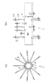
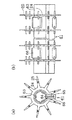
鳥獣害防止具71は、図9に示す様に、具体例4と全く同じ管状体63と取付補助具66とを備えているが、可撓性突起の枝部72、73の配置が具体例4のものとは異なる。
【0029】
即ち、図示左側面に突出する枝部72と、図示右側面に突出する枝部73とでは、管状体63の表面からの高さ位置が異なり、枝部72全体としては径の大きい円周上に配列され、枝部73全体として径の小さい円周上に配列されている。以上のように構成された鳥獣害防止具71でも、上記各具体例のものと同様の効果を奏する。特に、枝部72、73が、異なる高さ位置で障害物となっているため、より一層鳥がつかまりにくい。
【0030】
[具体例6]
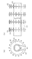
鳥獣害防止具81は、図10(a)、同図(b)に示す様に、具体例3と全く同じ鍔状体44と可撓性突起45とを備え、また、具体例4と全く同じ管状体63と取付補助具66とを備えてなる。
【0031】
以上のように構成された鳥獣害防止具81でも、上記各具体例のものと同様の効果を奏する。また、取付補助具66を使って電線への装脱着を行うので、装脱着作業が簡単である。
[具体例7]
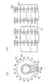
鳥獣害防止具91は、図11に示す様に、具体例6と全く同じ管状体63と取付補助具66とを備えているが、可撓性突起の枝部92、93の配置が具体例6のものとは異なる。
【0032】
即ち、図示左側面に突出する枝部92と、図示右側面に突出する枝部93とでは、具体例5と同様に、管状体63の表面からの高さ位置が異なり、枝部92全体としては径の大きい円周上に配列され、枝部93全体として径の小さい円周上に配列されている。
【0033】
以上のように構成された鳥獣害防止具91でも、上記各具体例のものと同様の効果を奏する。特に、枝部92、93が、異なる高さ位置で障害物となっているため、より一層鳥がつかまりにくい。
以上、本発明の具体例について説明したが、本発明の具体的な構成については上記具体例以外にも種々考えられる。
【0034】
例えば、上記具体例では、可撓性突起を合成ゴム製としたが、これ以外の弾性変形する素材を使ってもよい。
【0035】
【発明の効果】
以上の如く、本発明の鳥獣害防止具によれば、鳥獣害の発生を未然に防止することができ、特に、突起を管状体に対し比較的疎らに配置しても十分な鳥獣害防止効果が得られる。
【図面の簡単な説明】
【図1】 具体例1の鳥獣害防止具を示し、(a)はその正面図、(b)はその側面図である。
【図2】 具体例1の可撓性突起を示し、(a)はその側面図、(b)はその正面図である。
【図3】 具体例2の鳥獣害防止具を示し、(a)はその正面図、(b)はその側面図である。
【図4】 具体例2の鍔状体及び可撓性突起を示し、(a)はその正面図、(b)はA−A線断面図である。
【図5】 具体例3の鳥獣害防止具を示し、(a)はその正面図、(b)はその側面図である。
【図6】 具体例3の鍔状体及び可撓性突起を示し、(a)はその正面図、(b)はB−B線断面図である。
【図7】 具体例4の鳥獣害防止具を示し、(a)はその正面図、(b)はその側面図である。
【図8】 具体例4の取付補助具の正面図である。
【図9】 具体例5の鳥獣害防止具を示す側面図である。
【図10】 具体例6の鳥獣害防止具を示し、(a)はその正面図、(b)はその側面図である。
【図11】 具体例7の鳥獣害防止具を示す側面図である。
【符号の説明】
1,21,41,61,71,81,91・・・鳥獣害防止具、3,23,43,63・・・管状体、5,25,45・・・可撓性突起、7,64・・・切れ目、9・・・係合凸部、11・・・係合凹部、13,33,53・・・幹部、15,35,55,72,73,92,93・・・枝部、17,37,57・・・取付部、24,44・・・鍔状体、65・・・接触片、66・・・取付補助具。[0001]
BACKGROUND OF THE INVENTION
The present invention relates to a bird and animal damage prevention device used to prevent bird and animal damage caused by birds and animals being caught by electric wires or the like, such as funnel damage to a neighborhood or a short circuit accident.
[0002]
[Prior art]
2. Description of the Related Art Conventionally, as this type of bird and animal damage prevention device, a device comprising a tubular body that can be mounted on the outer periphery of an electric wire and a large number of protrusions provided on the outer periphery of the tubular body is known. According to such a bird and animal damage prevention device, since the protrusion becomes an obstacle and it becomes difficult for the bird to be caught by the electric wire and the bird does not come close to the electric wire, it is possible to prevent the dung damage to the neighborhood in advance.
[0003]
[Problems to be solved by the invention]
However, the prior art has the following problems.
In the conventional animal and animal damage prevention device, since it is necessary to prevent the birds from being caught between the protrusions, the above protrusions are arranged quite densely. It became a factor to put a load on. In addition, in order to arrange the projections densely, the number of projections to be implanted per unit length must be increased, and thus there is a problem that it takes time to plant the projections on the outer periphery of the tubular body.
[0004]
The present invention has been made to solve these problems, and the object of the present invention is to reduce the number of protrusions and reduce the weight as compared with the prior art, and to obtain a sufficient effect of preventing damage to birds and animals. The purpose is to provide birds and beasts.
[0005]
[Means for Solving the Problems]
In order to achieve the above-mentioned object, the present invention is as described in
A bird and animal damage prevention device comprising a tubular body that can be attached to the outer periphery of a wire such as an electric wire, and a number of protrusions provided on the outer periphery of the tubular body, and prevents the birds and beasts from approaching the wire by the protrusions. ,
The protrusion is
A trunk projecting in a substantially centrifugal direction of the tubular body;
A branch projecting substantially parallel to the axial direction of the tubular body from the trunk,
In addition, the outer periphery of the tubular body has a C-shaped inner periphery in contact with the outer periphery of the tubular body, and a flange having a shape that protrudes from the inner periphery and is fitted into a hole of the tubular body. A plurality of the trunks projecting from the outer edge of the flange, and the branch parts projecting from the trunks projecting at positions adjacent to each other in the axial direction of the tubular body, The height position from the surface of the tubular body is different between the branch portion projecting from the trunk portion toward the other trunk portion and the branch portion projecting from the other trunk portion toward the one trunk portion It is characterized by that.
[0006]
Moreover, the bird and animal harm prevention tool according to claim 2
The protrusion is flexible and can be deformed flexibly, and when the trunk part is stepped down, the branch part facing sideways is a flexible protrusion that is directed upward .
[0007]
DETAILED DESCRIPTION OF THE INVENTION
According to the bird and animal damage prevention device of the present invention, since the protrusion is provided on the outer periphery of the tubular body, this protrusion becomes an obstacle for birds and small animals, and it becomes difficult to be caught on the wire or to travel on the wire. As a result, birds and small animals do not get close to the wire. And in particular, since this projection has a trunk portion and a branch portion, even if this projection is installed relatively sparsely with respect to the tubular body, the branch portion becomes an obstacle between the installation positions of the projection, and the expected A sufficient effect can be secured. In addition, if the protrusions are placed loosely, the number of protrusions arranged per unit length can be reduced, so that it takes less time to manufacture the bird and animal damage prevention device, and the trunks are densely arranged. There is an advantage that the bird and animal damage prevention tool is lighter than the case, and the load applied to the electric wire is reduced.
Moreover, since the collar part is provided in the outer periphery of the tubular body, the effect which prevents the traffic of a small animal is still higher. In addition, since a plurality of protrusions project from the outer edge of the buttocks, the attachment of the plurality of protrusions can be completed simply by attaching a single collar to the tubular body, making it easy to manufacture bird and animal damage prevention tools. become able to.
Furthermore, since the branch portion is an obstacle at different height positions, it becomes extremely difficult for birds to be caught.
[0008]
Further, according to the wildlife prevention tool according to claim 2, since the protrusion is a flexible protrusion, it can be easily bent when subjected to an external force, and even if an operator touches it with his / her hand, the hand is damaged. In addition, even if a bird or the like comes into contact, it will not be hurt. Moreover, even if the bird and animal damage prevention tool falls as the electric wire is cut for some reason, the flexible projection does not damage the object at the dropping position.
[0009]
By the way, if it is a flexible protrusion, there is a possibility that it will be stepped on by birds and the like. In such a case, there is a possibility that the expected effect will not be obtained with the conventional protrusion, but in the case of the bird and animal damage prevention device of the present invention When the trunk is stepped down, the branch that turned to the side is turned upward, so that the bird is uncomfortable and the effect of dissipating the bird is not lost.
[0011]
In addition to the electric power supply wires, the bird and animal damage prevention device of the present invention can be mounted on a variety of wires wired overhead such as various communication cables and support wires stretched between power poles. is there.
Next, in order to further clarify the embodiment of the present invention, a specific example of a bird and animal damage prevention tool to which the present invention is applied will be described with reference to the drawings. Of the specific examples illustrated below, specific examples 5 and 7 correspond to the embodiments of the present invention, and other than specific examples 5 and 7 are reference examples. However, the specific examples 5 and 7 described below are merely examples of the embodiment of the present invention, and the embodiment of the present invention is not limited to the specific examples exemplified below.
[0012]
[Specific Example 1]
As shown in FIGS. 1A and 1B, the bird and animal
[0013]
Among these, the
The
[0014]
The bird and animal
[0015]
The bird and animal
[0016]
In particular, since the
Furthermore, since the
[0017]
Moreover, if the
[0018]
Furthermore, even if the bird grabs the
[Specific Example 2]
As shown in FIGS. 3A and 3B, the bird and animal
[0019]
Among these, the
The flange-
[0020]
The bird and animal
[0021]
The bird and animal
[0022]
[Specific Example 3]
As shown in FIG. 5A and FIG. 5B, the bird and animal
[0023]
Among these, the
The hook-shaped
[0024]
The bird and animal
[0025]
The bird and animal
[Specific Example 4]
As shown in FIGS. 7A and 7B, the bird and animal
[0026]
That is, the
[0027]
As shown in FIG. 8, the mounting
[0028]
The bird and animal
[Specific Example 5]
As shown in FIG. 9, the bird and animal
[0029]
That is, the
[0030]
[Specific Example 6]
As shown in FIGS. 10 (a) and 10 (b), the bird and animal
[0031]
The bird and animal
[Specific Example 7]
As shown in FIG. 11, the bird and animal
[0032]
That is, the
[0033]
The bird and animal
Although specific examples of the present invention have been described above, various specific configurations of the present invention are possible in addition to the specific examples.
[0034]
For example, in the above specific example, the flexible protrusion is made of synthetic rubber, but other elastically deformable materials may be used.
[0035]
【The invention's effect】
As described above, according to the bird and animal damage prevention device of the present invention, it is possible to prevent the occurrence of bird and animal damage, and in particular, even if the protrusions are arranged relatively sparsely with respect to the tubular body, a sufficient effect of preventing bird and animal damage is obtained. Is obtained.
[Brief description of the drawings]
BRIEF DESCRIPTION OF DRAWINGS FIG. 1 shows a bird and animal damage prevention tool of a specific example 1, wherein (a) is a front view thereof and (b) is a side view thereof.
FIGS. 2A and 2B show a flexible protrusion of Example 1, wherein FIG. 2A is a side view thereof, and FIG. 2B is a front view thereof.
FIGS. 3A and 3B show a bird and animal damage prevention device of a specific example 2, wherein FIG. 3A is a front view thereof, and FIG. 3B is a side view thereof.
4A and 4B show a bowl-like body and a flexible protrusion of Example 2, wherein FIG. 4A is a front view thereof, and FIG. 4B is a cross-sectional view taken along line AA.
FIGS. 5A and 5B show a bird and animal damage prevention device of Example 3, wherein FIG. 5A is a front view thereof, and FIG. 5B is a side view thereof.
6A and 6B show a saddle-like body and a flexible protrusion of Example 3, wherein FIG. 6A is a front view thereof, and FIG. 6B is a cross-sectional view taken along line BB.
7A and 7B show a bird and beast damage prevention device of Example 4, where FIG. 7A is a front view thereof, and FIG. 7B is a side view thereof.
FIG. 8 is a front view of a mounting aid of specific example 4;
FIG. 9 is a side view showing a bird and animal damage prevention device of Example 5.
10A and 10B show a bird and animal damage prevention device of Example 6, wherein FIG. 10A is a front view thereof, and FIG. 10B is a side view thereof.
FIG. 11 is a side view showing a bird and animal damage prevention device of Example 7.
[Explanation of symbols]
1, 21, 41, 61, 71, 81, 91 ... Bird and animal damage prevention device, 3, 23, 43, 63 ... Tubular body, 5, 25, 45 ... Flexible protrusion, 7, 64 ... Slot, 9 ... engagement projection, 11 ... engagement recess, 13,33,53 ... trunk, 15,35,55,72,73,92,93 ... branch , 17, 37, 57... Mounting portion, 24, 44... Bowl-shaped body, 65... Contact piece, 66.
Claims (2)
前記突起が、
前記管状体の略遠心方向へ突設された幹部と、
該幹部から前記管状体の軸方向と略平行に突設された枝部とを備えており、
しかも、前記管状体の外周には、前記管状体の外周に接するC字状の内周および当該内周から突出して前記管状体の穴に嵌め込まれた取付部を有する形状とされた鍔部が設けられて、該鍔部の外縁から複数の前記幹部が突設されていて、前記管状体の軸方向について隣り合う位置に突設された前記幹部それぞれに突設された前記枝部は、一方の幹部から他方の幹部に向かって突設された枝部と、前記他方の幹部から前記一方の幹部に向かって突設された枝部とで、管状体の表面からの高さ位置が異なる位置に設けられている
ことを特徴とする鳥獣害防止具。A bird and animal damage prevention device comprising a tubular body that can be attached to the outer periphery of a wire such as an electric wire, and a number of protrusions provided on the outer periphery of the tubular body, and prevents the birds and beasts from approaching the wire by the protrusions. ,
The protrusion is
A trunk projecting in a substantially centrifugal direction of the tubular body;
A branch projecting substantially parallel to the axial direction of the tubular body from the trunk,
In addition, the outer periphery of the tubular body has a C-shaped inner periphery in contact with the outer periphery of the tubular body, and a flange having a shape that protrudes from the inner periphery and is fitted into a hole of the tubular body. A plurality of the trunks projecting from the outer edge of the flange, and the branch parts projecting from the trunks projecting at positions adjacent to each other in the axial direction of the tubular body, The height position from the surface of the tubular body is different between the branch portion projecting from the trunk portion toward the other trunk portion and the branch portion projecting from the other trunk portion toward the one trunk portion Bird and animal damage prevention device characterized by being provided in.
前記突起が、柔軟に変形可能で、前記幹部が踏み倒された場合には、横を向いていた前記枝部が上に向けられる可撓性突起とされている
ことを特徴とする鳥獣害防止具。The bird and animal harm prevention tool according to claim 1,
The bird and animal damage prevention device characterized in that the protrusion is a flexible protrusion that can be flexibly deformed, and when the trunk portion is stepped down, the branch portion facing sideways is directed upward. .
Priority Applications (1)
| Application Number | Priority Date | Filing Date | Title |
|---|---|---|---|
| JP05636096A JP3775845B2 (en) | 1996-03-13 | 1996-03-13 | Bird and beast damage prevention equipment |
Applications Claiming Priority (1)
| Application Number | Priority Date | Filing Date | Title |
|---|---|---|---|
| JP05636096A JP3775845B2 (en) | 1996-03-13 | 1996-03-13 | Bird and beast damage prevention equipment |
Publications (2)
| Publication Number | Publication Date |
|---|---|
| JPH09248118A JPH09248118A (en) | 1997-09-22 |
| JP3775845B2 true JP3775845B2 (en) | 2006-05-17 |
Family
ID=13025086
Family Applications (1)
| Application Number | Title | Priority Date | Filing Date |
|---|---|---|---|
| JP05636096A Expired - Lifetime JP3775845B2 (en) | 1996-03-13 | 1996-03-13 | Bird and beast damage prevention equipment |
Country Status (1)
| Country | Link |
|---|---|
| JP (1) | JP3775845B2 (en) |
Families Citing this family (4)
| Publication number | Priority date | Publication date | Assignee | Title |
|---|---|---|---|---|
| JP2012034707A (en) * | 2011-11-18 | 2012-02-23 | Daito Kogyo Kk | Wildlife exclusion structure and wildlife exclusion tool thereof |
| JP5876429B2 (en) * | 2013-03-07 | 2016-03-02 | 東日本電信電話株式会社 | Cable protector |
| JP7024964B2 (en) * | 2017-12-05 | 2022-02-24 | 大都工業株式会社 | Bird's nest prevention device |
| JP7880599B2 (en) * | 2022-03-04 | 2026-06-26 | 株式会社愛洋産業 | Bird damage prevention device |
-
1996
- 1996-03-13 JP JP05636096A patent/JP3775845B2/en not_active Expired - Lifetime
Also Published As
| Publication number | Publication date |
|---|---|
| JPH09248118A (en) | 1997-09-22 |
Similar Documents
| Publication | Publication Date | Title |
|---|---|---|
| DE59905536D1 (en) | Protection arrangement on a wheel arch of a motor vehicle body shell structure | |
| JPH09248118A (en) | Bird and beast harm prevention equipment | |
| JP3901362B2 (en) | Bird damage prevention tool | |
| JP2712074B2 (en) | Bird flying prevention device | |
| KR200487394Y1 (en) | Protection collar for pets | |
| JP2505481Y2 (en) | Bird damage protector | |
| KR200207466Y1 (en) | A cross arm cover | |
| JP2573827Y2 (en) | Bushing terminal cover | |
| KR0132112Y1 (en) | Bird Nest Support | |
| JPH0736537U (en) | Bird damage protection tube | |
| JPH024423Y2 (en) | ||
| JP4517051B2 (en) | Bird and animal damage prevention device for electric wire | |
| JPS5846488Y2 (en) | Wire support part | |
| JP3910299B2 (en) | Cushion member mounting structure for roof rail | |
| JP2004222576A (en) | Bird nest prevention device | |
| KR200169885Y1 (en) | An apparatus for inducing birds to build a nest on the electric pole | |
| JPH03117314A (en) | Protecting tube and protective device against bird injury | |
| JP2521602Y2 (en) | CCP cable connection terminal box protective cover | |
| JPH0228715Y2 (en) | ||
| KR200170330Y1 (en) | Bird rebuffing device for electric poles | |
| JP2525082Y2 (en) | Tower bird harm prevention fence | |
| JPH09107613A (en) | Insulation cap for wire end | |
| JP3067288U (en) | Protective cover for fixing ring mounting bracket of ball-proof nets such as towers, masts and poles | |
| JP2538614Y2 (en) | Truck bed structure | |
| JPH026944Y2 (en) |
Legal Events
| Date | Code | Title | Description |
|---|---|---|---|
| A977 | Report on retrieval |
Free format text: JAPANESE INTERMEDIATE CODE: A971007 Effective date: 20050127 |
|
| A131 | Notification of reasons for refusal |
Free format text: JAPANESE INTERMEDIATE CODE: A131 Effective date: 20050201 |
|
| A521 | Written amendment |
Free format text: JAPANESE INTERMEDIATE CODE: A523 Effective date: 20050404 |
|
| A131 | Notification of reasons for refusal |
Free format text: JAPANESE INTERMEDIATE CODE: A131 Effective date: 20050628 |
|
| A521 | Written amendment |
Free format text: JAPANESE INTERMEDIATE CODE: A523 Effective date: 20050818 |
|
| TRDD | Decision of grant or rejection written | ||
| A01 | Written decision to grant a patent or to grant a registration (utility model) |
Free format text: JAPANESE INTERMEDIATE CODE: A01 Effective date: 20060131 |
|
| A61 | First payment of annual fees (during grant procedure) |
Free format text: JAPANESE INTERMEDIATE CODE: A61 Effective date: 20060221 |
|
| R150 | Certificate of patent (=grant) or registration of utility model |
Free format text: JAPANESE INTERMEDIATE CODE: R150 |
|
| FPAY | Renewal fee payment (prs date is renewal date of database) |
Free format text: PAYMENT UNTIL: 20090303 Year of fee payment: 3 |
|
| FPAY | Renewal fee payment (prs date is renewal date of database) |
Free format text: PAYMENT UNTIL: 20120303 Year of fee payment: 6 |
|
| FPAY | Renewal fee payment (prs date is renewal date of database) |
Free format text: PAYMENT UNTIL: 20150303 Year of fee payment: 9 |
|
| EXPY | Cancellation because of completion of term |