JP3778286B2 - Cover gasket for hard disk drive - Google Patents
Cover gasket for hard disk drive Download PDFInfo
- Publication number
- JP3778286B2 JP3778286B2 JP2002525663A JP2002525663A JP3778286B2 JP 3778286 B2 JP3778286 B2 JP 3778286B2 JP 2002525663 A JP2002525663 A JP 2002525663A JP 2002525663 A JP2002525663 A JP 2002525663A JP 3778286 B2 JP3778286 B2 JP 3778286B2
- Authority
- JP
- Japan
- Prior art keywords
- adhesive
- rubber
- cover
- bonding
- cross
- Prior art date
- Legal status (The legal status is an assumption and is not a legal conclusion. Google has not performed a legal analysis and makes no representation as to the accuracy of the status listed.)
- Expired - Fee Related
Links
- 239000000853 adhesive Substances 0.000 claims description 90
- 230000001070 adhesive effect Effects 0.000 claims description 89
- 229920001971 elastomer Polymers 0.000 claims description 62
- 239000005060 rubber Substances 0.000 claims description 62
- 238000010586 diagram Methods 0.000 description 6
- 239000002313 adhesive film Substances 0.000 description 4
- 238000000034 method Methods 0.000 description 4
- 230000000694 effects Effects 0.000 description 3
- 239000010935 stainless steel Substances 0.000 description 3
- 229910001220 stainless steel Inorganic materials 0.000 description 3
- PXHVJJICTQNCMI-UHFFFAOYSA-N Nickel Chemical compound [Ni] PXHVJJICTQNCMI-UHFFFAOYSA-N 0.000 description 2
- 230000000052 comparative effect Effects 0.000 description 2
- 238000010438 heat treatment Methods 0.000 description 2
- 230000009191 jumping Effects 0.000 description 2
- 238000000465 moulding Methods 0.000 description 2
- NLHHRLWOUZZQLW-UHFFFAOYSA-N Acrylonitrile Chemical compound C=CC#N NLHHRLWOUZZQLW-UHFFFAOYSA-N 0.000 description 1
- 229910000838 Al alloy Inorganic materials 0.000 description 1
- 229910001369 Brass Inorganic materials 0.000 description 1
- 241000258920 Chilopoda Species 0.000 description 1
- JOYRKODLDBILNP-UHFFFAOYSA-N Ethyl urethane Chemical compound CCOC(N)=O JOYRKODLDBILNP-UHFFFAOYSA-N 0.000 description 1
- YCKRFDGAMUMZLT-UHFFFAOYSA-N Fluorine atom Chemical compound [F] YCKRFDGAMUMZLT-UHFFFAOYSA-N 0.000 description 1
- 239000005062 Polybutadiene Substances 0.000 description 1
- 229920006311 Urethane elastomer Polymers 0.000 description 1
- 239000010951 brass Substances 0.000 description 1
- 239000003795 chemical substances by application Substances 0.000 description 1
- 230000006835 compression Effects 0.000 description 1
- 238000007906 compression Methods 0.000 description 1
- 229920003244 diene elastomer Polymers 0.000 description 1
- 238000005516 engineering process Methods 0.000 description 1
- 229920006332 epoxy adhesive Polymers 0.000 description 1
- HQQADJVZYDDRJT-UHFFFAOYSA-N ethene;prop-1-ene Chemical group C=C.CC=C HQQADJVZYDDRJT-UHFFFAOYSA-N 0.000 description 1
- 229910052731 fluorine Inorganic materials 0.000 description 1
- 239000011737 fluorine Substances 0.000 description 1
- 239000007788 liquid Substances 0.000 description 1
- 239000000463 material Substances 0.000 description 1
- 229910052751 metal Inorganic materials 0.000 description 1
- 239000002184 metal Substances 0.000 description 1
- 229910052759 nickel Inorganic materials 0.000 description 1
- 238000007747 plating Methods 0.000 description 1
- 229920002857 polybutadiene Polymers 0.000 description 1
- 238000003825 pressing Methods 0.000 description 1
- 238000007789 sealing Methods 0.000 description 1
- 229920001187 thermosetting polymer Polymers 0.000 description 1
Images


Classifications
-
- G—PHYSICS
- G11—INFORMATION STORAGE
- G11B—INFORMATION STORAGE BASED ON RELATIVE MOVEMENT BETWEEN RECORD CARRIER AND TRANSDUCER
- G11B33/00—Constructional parts, details or accessories not provided for in the other groups of this subclass
- G11B33/12—Disposition of constructional parts in the apparatus, e.g. of power supply, of modules
- G11B33/121—Disposition of constructional parts in the apparatus, e.g. of power supply, of modules the apparatus comprising a single recording/reproducing device
-
- G—PHYSICS
- G11—INFORMATION STORAGE
- G11B—INFORMATION STORAGE BASED ON RELATIVE MOVEMENT BETWEEN RECORD CARRIER AND TRANSDUCER
- G11B33/00—Constructional parts, details or accessories not provided for in the other groups of this subclass
- G11B33/14—Reducing influence of physical parameters, e.g. temperature change, moisture, dust
- G11B33/1446—Reducing contamination, e.g. by dust, debris
- G11B33/1466—Reducing contamination, e.g. by dust, debris sealing gaskets
Landscapes
- Gasket Seals (AREA)
- Adhesives Or Adhesive Processes (AREA)
Description
【0001】
【発明の属する技術分野】
本発明は、ハードディスク装置に用いられるカバーガスケットに関するものである。
【0002】
【従来の技術】
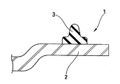
従来から、図10に示すように、ハードディスクのトップカバー2にシール用ガスケットとしてゴム3を組み合わせてなるハードディスク装置用カバーガスケット1が知られており、このカバー2とゴム3との組み合わせ手段として、カバー2にゴム3を一体的に成型したもの、ゴム3にステンレス製芯金入りのものを用いてカバー2に重ねたもの、カバー2に発泡ウレタンまたは液状ゴムを塗布して硬化させたもの、またはカバー2とゴム3とを接着剤を用いて後接着したもの等が挙げられる。
【0003】
その中で、カバー2とゴム3とを接着剤を用いて後接着する場合には、接着剤のはみ出しによる接着不良が問題となっている。
【0004】
この接着剤のはみ出しやゴム3の剥がれの発生メカニズムは、以下のようなものである。
【0005】
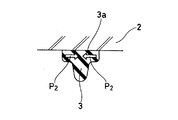
すなわち、図11に示すように、カバー2とゴム3とを接着剤(図示せず)を用いて後接着する場合には、ゴム3の接着面3aに接着剤を塗布してカバー2およびゴム3を接着冶具11にセットした後、図12に示すように上部(上冶具12側)から荷重Pをかけながら加熱および接着を行なっており、このとき上記荷重Pの大きさが大き過ぎると、ゴム3が下冶具13に強く押し付けられて外方向に過剰な力P1が発生する。したがって、この過剰な力P1によって、ゴム3の接着面3aに塗布された接着剤4がかき出され、これが接着剤4のはみ出しの原因となっている。また、これに伴ってカバー2とゴム3との間に介在する接着膜が薄くなるために、接着力の低下にも繋がる。更に、冶具11からトップカバー2を取り出す際にゴム3が弾性復帰するために、図13に示すように接着時とは逆方向にせん断応力P2が発生し、よってこれがゴム3の剥がれの原因となっている。
【0006】
上記荷重Pすなわち接着部の加圧力は、上記したような接着剤4のはみ出しが生じたり、接着膜が薄くなったりすることのないよう荷重の大きさをコントロールし、また、ゴム3を押し過ぎることがないように冶具11には受け14(図11参照)を設けている。
【0007】
しかしながら、カバー2の接着部の平面度が良くないと、接着部全面を接着するために大きな加圧力が必要であり、たとえ冶具11に受け14を設けても、カバー2の部分的な反りによって、接着剤4のはみ出しが大きくなったり、接着剤4の膜厚が薄くなったりする。カバー2はこれをプレス成形によって成形するものであるが、特にステンレス板等によってカバー2をプレス成形する場合にはプレス後にスプリングバックが生じるために、その平面度を良好な接着が可能なほど十分に良くすることは困難である。
【0008】
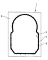
また、接着剤4を接着面に塗布した後、接着面を貼り合わせ、加圧して熱盤の上に乗せたとき、当初、加圧力と接着剤4の表面張力とが釣り合って接着面の間にとどまっていた接着剤4は、温度が上昇するのに伴って表面張力を失い、ある温度で釣り合いがくずれ、接着剤4が接着面から押し出される。このとき、釣り合いの弱い部分から先に接着剤4が押し出されるため、また、接着剤4は温度上昇により粘度も低下しているために、接着面の外周全体から接着剤4が均一に押し出されるのではなく、複数の箇所から不均一に飛び出すように押し出される。したがってその結果、はみ出し後の状態は、図14のモデル図に示すように、ゴム3の両側から接着剤4がムカデの脚のようにギザギザに飛び出したような形状になる。
【0009】
また、第2517797号日本国特許公報に、カバーとゴムとを接着剤を用いて後接着するカバーガスケットが掲載されているが、この公報掲載の従来技術は接着剤をはみ出させて、はみ出した接着剤によってゴムバリを被覆固定しようとするものであり、接着剤のはみ出しを積極的に容認するものである。
【0010】
【特許文献1】
第2517797号日本国特許公報
【0011】
【発明が解決しようとする課題】
本発明は以上の点に鑑みて、カバーとゴムとを接着剤を用いて後接着するハードディスク装置用カバーガスケットにおいて、接着剤のはみ出しやゴムの剥がれを極力防止することが可能なカバーガスケットを提供することを目的とする。
【0012】
【課題を解決するための手段】
上記目的を達成するため、本発明の請求項1によるカバーガスケットは、カバーとゴムとを接着剤を用いて後接着してなるハードディスク装置用カバーガスケットにおいて、前記カバーまたはゴムの接着面に塗布した接着剤が接着時の加圧力によりはみ出すのを防止する凹部を前記接着面に設け、前記凹部は、ゴムの接着面の幅方向端部に設けられていることを特徴とするものである。
【0013】
上記構成を備えた本発明の請求の範囲第1項によるカバーガスケットのようにカバーまたはゴムの接着面に凹部を設けると、たとえ接着時の加圧力が大きくても凹部に接着剤が貯留されるために、接着剤のはみ出しを最小限に抑えることが可能となる。また、凹部に一部の接着剤が貯留する分、接着膜厚が厚くなるために、接着力を強化することが可能となる。凹部はゴムの接着面の幅方向端部に設けられ、よって凹部はゴムの側面にも開口することになる。
【0014】
尚、後接着とは、カバーおよびゴムをそれぞれ単品で製品形状に形成してから両者を接着することである。
【0015】
【発明の実施の形態】
つぎに本発明の実施例を図面にしたがって説明する。
【0016】
第一実施例・・・
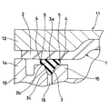
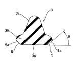
図1は、本発明の第一実施例に係るカバーガスケット1を、その構成部品であるカバー2とゴム(狭義のガスケットとも称する)3とを接着剤4を用いて後接着するために接着冶具11にセットした状態を示しており、図2に拡大して示すように、ゴム3の接着面3aの幅方向両端部にそれぞれ面取り状を呈する接着剤貯留用の凹部5が対称的に予め設けられており、図1に示したように、ゴム3の接着面3aに塗布された接着剤4の一部がこの凹部5に貯留した状態で、カバー2とゴム3とが接着されるようになっている。
【0017】
カバー2は、ステンレス、アルミ合金または、黄銅に無電解ニッケルメッキを施したもの等よりなる素材またはそれらの積層材をプレス成形すること等によって成形されている。
【0018】
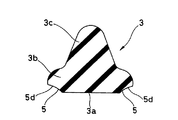
ゴム3は、比較的幅広のフランジ部3bの一面をカバー2に対する接着面3aとするとともに、その反対側の幅方向中央に比較的幅狭のリップ部3cを一体成形したものであって、FKM(フッ素ゴム)、EPDM(エチレン・プロピレン・ジエンゴム)、NBR(アクリロニトリル・ブタジエンゴム)またはウレタンゴム等によって成形されており、その硬度をHs20〜80程度に設定されている。また、その断面形状における幅寸法は実寸で1.5〜2mm程度、高さ寸法は同じく実寸で1.5mm程度に形成されている。
【0019】
面取り状の凹部5は、ゴム3の平面レイアウトに沿ってゴム3の全長に亙って設けられており、その断面形状における高さ寸法を実寸で0.2mm程度またはそれ以下の大きさに形成されている。また、この面取り状の凹部5は、接着面3aの幅方向端部を斜めにカットしたような形状を呈して、断面直線状の傾斜面5aを有しており、この傾斜面5aの接着面3aに対する傾斜角度θを20〜70度に設定し、40度とすると更に良い。このような数値に傾斜角度θを設定する理由は、接着剤4の排出抵抗を抑え、かつ接着剤4を貯める容積を十分に確保できるからである。この断面形状は、傾斜面5aが接着面3aに対して非直角で交差していて、凹部5内において接着剤4のはみ出し方向の出口が徐々に広がる形状である。
【0020】
接着剤4には、1液性熱硬化タイプのエポキシ系接着剤が多く用いられ、この接着剤4は、スタンプによる転写等によりゴム3に塗布される。
【0021】
また、図示した接着冶具11は、上冶具12および下冶具13の組み合わせによって構成されており、このうち下冶具13の上面に、接着時に上冶具12との間にカバー2を挟み込むことによってゴム3の圧縮量を制限する受け14や、同じく接着時にゴム3を支持する支持部15および負圧吸引口16等が設けられている。
【0022】
上記構成のカバーガスケット1においては、上記したようにゴム3の接着面3aの幅方向両端部にそれぞれ面取り状を呈する接着剤貯留用の凹部5が対称的に設けられているために、ゴム3の接着面3aに接着剤4を塗布したときに接着剤4の一部がこの面取り状の凹部5に貯留され、この状態で接着が行なわれる。したがって、たとえ接着時の加圧力が大きくても面取り状の凹部5に接着剤4が貯留されるために、第3図のモデル図に示したように、接着剤4のはみ出しを最小限に抑えることができる。また、接着剤4が面取り状の凹部5に貯留するので、接着剤4の塗布面積が増し、よって接着力を強化することができ、これによりゴム3に剥がれが発生するのを抑えることができる。
【0023】
尚、上記第一実施例では、ゴム3の接着面3aの幅方向端部に凹部5を面取り状のものとして設けたが、この凹部5は以下に例示するような切欠状のものであっても良い。
【0024】
第二実施例・・・
図4に示すように、接着面3aに対して所定の傾斜角度を備えた断面直線状の傾斜面5aおよび、接着面3aに対して平行な断面直線状の水平面5bの組み合わせによって凹部5の内面が形成されている。この断面形状は、上記第一実施例と同様、傾斜面5aが接着面3aに対して非直角で交差していて、凹部5内において接着剤4のはみ出し方向の出口が徐々に広がる形状である。
【0025】
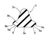
第三実施例・・・
図5に示すように、断面凸曲線状の曲面5cによって凹部5の内面が形成されている。この断面形状は、曲面5cが接着面3aに対して非直角で交差していて、凹部5内において接着剤4のはみ出し方向の出口が徐々に広がる形状である。
【0026】
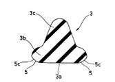
第四実施例・・・
図6に示すように、断面凹曲線状の曲面5dによって凹部5の内面が形成されている。この断面形状は、上記第三実施例と同様、曲面5dが接着面3aに対して非直角で交差していて、凹部5内において接着剤4のはみ出し方向の出口が徐々に広がる形状である。
【0027】
第五実施例・・・
図7に示すように、断面凹曲線状の曲面5dによって凹部5の内面が形成されている。この断面形状においては、曲面5dが接着面3aに対して直角に交差している。
【0028】
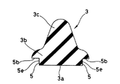
第六実施例・・・
図8に示すように、接着面3aに対して直角な断面直線状の垂直面5eおよび、接着面3aに対して平行な断面直線状の水平面5bの組み合わせによって凹部5の内面が形成されている。この断面形状においては、垂直面5eが接着面3aに対して直角に交差している。
【0029】
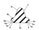
第七実施例・・・
図9に示すように、接着面3aに対して直角な断面直線状の垂直面5e、接着面3aに対して所定の傾斜角度を備えた断面直線状の傾斜面5aおよび、接着面3aに対して平行な断面直線状の水平面5bの組み合わせによって凹部5の内面が形成されている。この断面形状においては、垂直面5eが接着面3aに対して直角に交差している。
【0030】
これらの断面形状よりなる凹部5は何れもその内部に接着剤4を貯留する作用を奏するが、特に上記第一、第二、第三または第四実施例のように傾斜面5aまたは曲面5dが接着面3aに対して非直角で交差していて、凹部5内において接着剤4のはみ出し方向の出口が徐々に広がる形状とされていると、この出口における接着剤4の排出抵抗が小さく、よってゴム3の接着面3aに塗布された接着剤4が温度が上昇する前にじわりとゴム3とカバー2との間から凹部5へと流れ出てくるために、接着剤4の飛び出し現象を特に有効に抑えることができる。また、接着剤4が粘度の高い流体であって、角度のついたゴム3の壁に沿って流れ出てくることによっても、接着剤4の飛び出し現象を特に有効に抑えることができる。この作用効果を期待することができるのは、交差角度(上記θ)が20〜70度程度の範囲内にある場合と考えられる。
【0031】
【発明の効果】
本発明は、以下の効果を奏する。
【0032】
すなわち、上記構成を備えた本発明の請求項1によるカバーガスケットにおいては、カバーとゴムとを接着剤を用いて後接着してなるガスケットにおいてカバーまたはゴムの接着面に塗布した接着剤が接着時の加圧力によりはみ出すのを防止する凹部が接着面に設けられ、凹部はゴムの接着面の幅方向端部に設けられているために、接着面に接着剤を塗布したときに接着剤の一部がこの凹部に貯留され、この状態で接着が行なわれることになる。したがって、たとえ接着時の加圧力が大きくても凹部に接着剤が貯留されるために、接着剤のはみ出しを最小限に抑えることができる。また、凹部に一部の接着剤が貯留する分、接着膜厚が厚くなるために、接着力を強化することができ、これによりゴムに剥がれが発生するのを抑えることができる。
【0033】
【図面の簡単な説明】
【図1】本発明の第一実施例に係るカバーガスケットの接着工程を示す要部断面図
【図2】同カバーガスケットの構成部品であるゴムの断面図
【図3】同カバーガスケットの完成状態を示す比較モデル図
【図4】本発明の第二実施例に係るカバーガスケットの構成部品であるゴムの断面図
【図5】本発明の第三実施例に係るカバーガスケットの構成部品であるゴムの断面図
【図6】本発明の第四実施例に係るカバーガスケットの構成部品であるゴムの断面図
【図7】本発明の第五実施例に係るカバーガスケットの構成部品であるゴムの断面図
【図8】本発明の第六実施例に係るカバーガスケットの構成部品であるゴムの断面図
【図9】本発明の第七実施例に係るカバーガスケットの構成部品であるゴムの断面図
【図10】従来例に係るカバーガスケットの要部断面図
【図11】同カバーガスケットの接着工程を示す要部断面図
【図12】同カバーガスケットの接着工程における加圧力の作用方向を示す説明図
【図13】同カバーガスケットの接着工程におけるせん断応力の発生方向を示す説明図
【図14】同カバーガスケットの完成状態を示す比較モデル図
【符号の説明】
【0034】
1 ハードディスク装置用カバーガスケット
2 カバー
3 ゴム
3a 接着面
4 接着剤
5 凹部 [0001]
BACKGROUND OF THE INVENTION
The present invention relates to a cover gasket used in a hard disk device.
[0002]
[Prior art]
Conventionally, as shown in FIG. 10 , a hard disk
[0003]
In this case, when the
[0004]
The occurrence mechanism of the adhesive protrusion and the
[0005]
That is, as shown in FIG. 11 , when the
[0006]
The load P, that is, the pressure applied to the bonded portion, controls the magnitude of the load so that the adhesive 4 does not protrude or the adhesive film does not become thin, and the
[0007]
However, if the flatness of the bonding portion of the
[0008]
Also, after the adhesive 4 is applied to the adhesive surface, when the adhesive surface is bonded, pressed and placed on the heating plate, initially, the applied pressure and the surface tension of the adhesive 4 are balanced so that there is a gap between the adhesive surfaces. The adhesive 4 staying at the point loses its surface tension as the temperature rises, becomes unbalanced at a certain temperature, and the adhesive 4 is pushed out from the adhesive surface. At this time, since the adhesive 4 is pushed out from the weakly balanced portion first, and the viscosity of the adhesive 4 is also lowered due to the temperature rise, the adhesive 4 is pushed out uniformly from the entire outer periphery of the bonding surface. Rather than being pushed out, it is pushed out in a non-uniform manner. Therefore, as a result, as shown in the model diagram of FIG. 14 , the state after the protrusion becomes a shape in which the adhesive 4 protrudes from both sides of the
[0009]
In addition, in Japanese Patent No. 2517797, a cover gasket for post-bonding a cover and rubber using an adhesive is described. However, the conventional technology disclosed in this publication allows the adhesive to protrude and the adhesive to protrude. It is intended to cover and fix rubber burrs with an agent, and positively tolerate the protruding adhesive.
[0010]
[Patent Document 1]
Japanese Patent No. 2517797
[Problems to be solved by the invention]
In view of the above points, the present invention provides a cover gasket for a hard disk device cover gasket in which a cover and a rubber are post-bonded using an adhesive, and capable of preventing the adhesive from protruding and the rubber from peeling off as much as possible. The purpose is to do.
[0012]
[Means for Solving the Problems]
In order to achieve the above object, a cover gasket according to
[0013]
When a concave portion is provided on the cover or rubber adhesive surface as in the cover gasket according to the first aspect of the present invention having the above-described configuration, the adhesive is stored in the concave portion even if the pressure applied during bonding is large. Therefore, it is possible to minimize the protrusion of the adhesive. In addition, since the adhesive film thickness is increased by a portion of the adhesive stored in the recess, the adhesive force can be strengthened. The recess is provided at the end in the width direction of the adhesive surface of the rubber, so that the recess also opens on the side of the rubber.
[0014]
The post-adhesion means that the cover and the rubber are individually formed into a product shape and then bonded together.
[0015]
DETAILED DESCRIPTION OF THE INVENTION
Next, embodiments of the present invention will be described with reference to the drawings.
[0016]
First embodiment ...
FIG. 1 shows an adhesive jig for post-bonding a
[0017]
The
[0018]
The
[0019]
The chamfered
[0020]
As the adhesive 4, a one-component thermosetting epoxy adhesive is often used, and this adhesive 4 is applied to the
[0021]
The illustrated
[0022]
In the
[0023]
In the first embodiment, the
[0024]
Second embodiment ...
As shown in FIG. 4 , the inner surface of the
[0025]
Third embodiment ...
As shown in FIG. 5 , the inner surface of the
[0026]
Fourth embodiment ...
As shown in FIG. 6 , the inner surface of the
[0027]
Fifth Example ...
As shown in FIG. 7 , the inner surface of the
[0028]
Sixth Example ...
As shown in FIG. 8 , the inner surface of the
[0029]
Seventh Example ...
As shown in FIG. 9 , with respect to the
[0030]
Each of the
[0031]
【The invention's effect】
The present invention has the following effects.
[0032]
That is, in the cover gasket according to the first aspect of the present invention having the above-described configuration, the adhesive applied to the cover or the adhesive surface of the rubber in the gasket formed by post-bonding the cover and the rubber using an adhesive is bonded. A recess is provided on the adhesive surface to prevent it from sticking out due to the applied pressure , and the recess is provided at the end of the rubber adhesive surface in the width direction. The part is stored in the recess, and bonding is performed in this state. Therefore, even if the pressure applied at the time of bonding is large, the adhesive is stored in the concave portion, so that the protrusion of the adhesive can be minimized. In addition, since the adhesive film thickness is increased by the amount of the adhesive that is stored in the recess, the adhesive force can be strengthened, thereby preventing the rubber from peeling off.
[0033]
[Brief description of the drawings]
FIG. 1 is a cross-sectional view of an essential part showing a bonding process of a cover gasket according to a first embodiment of the present invention.
FIG. 2 is a cross-sectional view of rubber that is a component of the cover gasket
FIG. 3 is a comparative model diagram showing the completed state of the cover gasket.
FIG. 4 is a cross-sectional view of rubber that is a component part of a cover gasket according to a second embodiment of the present invention.
FIG. 5 is a cross-sectional view of rubber that is a component part of a cover gasket according to a third embodiment of the present invention.
FIG. 6 is a cross-sectional view of rubber that is a component part of a cover gasket according to a fourth embodiment of the present invention.
FIG. 7 is a sectional view of rubber that is a component part of a cover gasket according to a fifth embodiment of the present invention.
FIG. 8 is a cross-sectional view of rubber that is a component part of a cover gasket according to a sixth embodiment of the present invention.
FIG. 9 is a cross-sectional view of rubber that is a component part of a cover gasket according to a seventh embodiment of the present invention.
FIG. 10 is a cross-sectional view of main parts of a cover gasket according to a conventional example.
FIG. 11 is a cross-sectional view of the main part showing the bonding process of the cover gasket.
FIG. 12 is an explanatory diagram showing the direction of pressure applied in the cover gasket bonding process.
FIG. 13 is an explanatory diagram showing the direction of shear stress generation in the cover gasket bonding process.
FIG. 14 is a comparative model diagram showing the completed state of the cover gasket.
[Explanation of symbols]
[0034]
1 Cover gasket for hard disk drive
2 Cover
3 Rubber
3a Adhesive surface
4 Adhesive
5 recesses
Claims (1)
前記カバー(2)またはゴム(3)の接着面に塗布した接着剤(4)が接着時の加圧力によりはみ出すのを防止する凹部(5)を前記接着面に設け、
前記凹部(5)は、ゴム(3)の接着面(3a)の幅方向端部に設けられていることを特徴とするハードディスク装置用カバーガスケット。In the cover gasket (1) for a hard disk device, in which the cover (2) and the rubber (3) are post-bonded using an adhesive (4),
A concave portion (5) for preventing the adhesive (4) applied to the adhesive surface of the cover (2) or rubber (3) from protruding due to the applied pressure during adhesion is provided on the adhesive surface ;
The said recessed part (5) is provided in the width direction edge part of the adhesion surface (3a) of rubber | gum (3), The cover gasket for hard disk devices characterized by the above-mentioned .
Applications Claiming Priority (5)
| Application Number | Priority Date | Filing Date | Title |
|---|---|---|---|
| JP2000264831 | 2000-09-01 | ||
| JP2000264831 | 2000-09-01 | ||
| JP2000344617 | 2000-11-13 | ||
| JP2000344617 | 2000-11-13 | ||
| PCT/JP2001/007368 WO2002021534A1 (en) | 2000-09-01 | 2001-08-28 | Cover gasket for hard disk device |
Publications (2)
| Publication Number | Publication Date |
|---|---|
| JPWO2002021534A1 JPWO2002021534A1 (en) | 2004-01-15 |
| JP3778286B2 true JP3778286B2 (en) | 2006-05-24 |
Family
ID=26599043
Family Applications (1)
| Application Number | Title | Priority Date | Filing Date |
|---|---|---|---|
| JP2002525663A Expired - Fee Related JP3778286B2 (en) | 2000-09-01 | 2001-08-28 | Cover gasket for hard disk drive |
Country Status (6)
| Country | Link |
|---|---|
| US (1) | US6769699B2 (en) |
| EP (1) | EP1315168B1 (en) |
| JP (1) | JP3778286B2 (en) |
| CN (1) | CN1232983C (en) |
| AU (1) | AU2001280206A1 (en) |
| WO (1) | WO2002021534A1 (en) |
Families Citing this family (25)
| Publication number | Priority date | Publication date | Assignee | Title |
|---|---|---|---|---|
| JP2004076877A (en) * | 2002-08-20 | 2004-03-11 | Nok Corp | Gasket |
| FR2856951B1 (en) * | 2003-07-01 | 2006-06-23 | Saint Gobain | GLAZING COMPRISING A REINFORCING ELEMENT |
| AU2003280644A1 (en) * | 2003-10-30 | 2005-05-19 | Nok Corporation | Thermoplastic elastomer composition, gasket, molded gasket, and structure for sealing between two members |
| US20050189720A1 (en) * | 2004-02-27 | 2005-09-01 | R & D Dynamics Corporation | Dynamic seal for use in high-speed turbomachinery |
| JP4148173B2 (en) * | 2004-03-31 | 2008-09-10 | Nok株式会社 | Gasket for fuel cell |
| TWI233966B (en) * | 2004-12-03 | 2005-06-11 | Benq Corp | Structure with resilient member and assembly method thereof |
| DE102004062880A1 (en) * | 2004-12-27 | 2006-07-06 | Siemens Ag | Display instrument and method for producing and disassembling a display instrument |
| US20060187577A1 (en) * | 2005-01-31 | 2006-08-24 | Metalform Asia Pte Ltd. | Disk drive cover |
| WO2007086463A1 (en) * | 2006-01-25 | 2007-08-02 | Kabushiki Kaisha Toyota Jidoshokki | Electric compressor |
| US7852601B1 (en) | 2006-10-18 | 2010-12-14 | Western Digital Technologies, Inc. | Radial top cover gasket for disk drives |
| US20080191474A1 (en) * | 2007-02-12 | 2008-08-14 | Kotz George J | Tri-Lobed O-Ring Seal |
| JP2008269696A (en) * | 2007-04-19 | 2008-11-06 | Hitachi Global Storage Technologies Netherlands Bv | Magnetic disk drive and feedthrough soldering method |
| JP5179120B2 (en) * | 2007-08-24 | 2013-04-10 | 株式会社ブリヂストン | Multistage gasket |
| US8031431B1 (en) | 2009-03-02 | 2011-10-04 | Western Digital Technologies, Inc. | Disk drive having a top cover with anchor tabs |
| US8973921B2 (en) * | 2010-03-09 | 2015-03-10 | Baker Hughes Incorporated | High temperature/high pressure seal |
| US8695835B2 (en) * | 2011-02-03 | 2014-04-15 | Weener Plastik Gmbh | Closure cap for a fluid container and method for the fabrication |
| KR20130006962A (en) * | 2011-06-28 | 2013-01-18 | 시게이트 테크놀로지 인터내셔날 | Hard disk drive |
| JP2013223312A (en) * | 2012-04-16 | 2013-10-28 | Nippon Densan Corp | Base unit, spindle motor, and disk driving device |
| US10072776B2 (en) | 2015-08-20 | 2018-09-11 | Deere & Company | Fluid connector with annular groove and seal |
| US9734874B1 (en) | 2016-02-02 | 2017-08-15 | Western Digital Technologies, Inc. | Adhesive leak channel structure for hermetic sealing of a hard disk drive |
| CN107508950B (en) * | 2017-08-16 | 2020-08-25 | Oppo广东移动通信有限公司 | Housing assembly, sealing method thereof and electronic device |
| US11104101B2 (en) * | 2019-05-01 | 2021-08-31 | Autoliv Asp, Inc. | Systems and methods for sealing an airbag inflator base |
| WO2023027070A1 (en) * | 2021-08-27 | 2023-03-02 | 日本発條株式会社 | Cover and recording device |
| JP2024073713A (en) * | 2022-11-18 | 2024-05-30 | ニデック株式会社 | Base plate and disk drive |
| US20250299703A1 (en) * | 2024-03-19 | 2025-09-25 | Western Digital Technologies, Inc. | Hard disk drive embedded gasket base |
Family Cites Families (16)
| Publication number | Priority date | Publication date | Assignee | Title |
|---|---|---|---|---|
| US3544066A (en) * | 1967-01-03 | 1970-12-01 | Pratt Co Henry | Valve seat structure |
| US3694894A (en) * | 1970-01-14 | 1972-10-03 | Parker Hannifin Corp | Method of inserting a seal in a face-cut groove |
| US4363192A (en) * | 1981-03-30 | 1982-12-14 | Soucy Armand L | Window mounting system |
| GB2143569B (en) * | 1983-07-26 | 1986-09-10 | Draftex Ind Ltd | Windscreen mounting |
| US4527807A (en) * | 1984-06-25 | 1985-07-09 | Dallas Corporation | Panel edge gasket |
| FR2616465B1 (en) * | 1987-06-12 | 1989-10-27 | Couvraneuf | VERTICAL FRONT JOINT FOR SEALING BETWEEN TWO WALLS |
| JP2517797B2 (en) * | 1990-12-27 | 1996-07-24 | 信越化学工業株式会社 | Packing assembly for hard disk device |
| JP2856577B2 (en) | 1991-09-26 | 1999-02-10 | 株式会社東芝 | Superconducting element |
| JPH05290563A (en) | 1992-04-10 | 1993-11-05 | Fujitsu Ltd | Closed structure |
| US5422766A (en) * | 1994-01-03 | 1995-06-06 | Maxtor Corporation | Gasket for sealing a disk drive assembly |
| DE4404348A1 (en) * | 1994-02-11 | 1995-08-17 | Fritz Richard Gmbh & Co Kg | Process for the production and installation of a glass pane with a frame, in particular on a vehicle part |
| US5647255A (en) * | 1995-09-27 | 1997-07-15 | Quantum Corporation | Expandable gasket for a head disk assembly of a disk drive |
| JPH1144362A (en) | 1997-07-28 | 1999-02-16 | Nok Corp | Gasket |
| US6030104A (en) * | 1997-10-21 | 2000-02-29 | Shu; Cheng Cheng | Soft shelled lamp shade |
| US6202983B1 (en) * | 1999-10-13 | 2001-03-20 | Thomas A. Hartman | Valve seal structured to prevent circumferential slippage |
| US6494466B1 (en) * | 2000-04-20 | 2002-12-17 | Thomas A. Hartman | Valve seal construction with non-congruent side serrations |
-
2001
- 2001-08-28 EP EP01958561A patent/EP1315168B1/en not_active Expired - Lifetime
- 2001-08-28 CN CNB018043186A patent/CN1232983C/en not_active Expired - Fee Related
- 2001-08-28 US US10/148,892 patent/US6769699B2/en not_active Expired - Lifetime
- 2001-08-28 JP JP2002525663A patent/JP3778286B2/en not_active Expired - Fee Related
- 2001-08-28 WO PCT/JP2001/007368 patent/WO2002021534A1/en not_active Ceased
- 2001-08-28 AU AU2001280206A patent/AU2001280206A1/en not_active Abandoned
Also Published As
| Publication number | Publication date |
|---|---|
| EP1315168A1 (en) | 2003-05-28 |
| CN1416573A (en) | 2003-05-07 |
| AU2001280206A1 (en) | 2002-03-22 |
| WO2002021534A1 (en) | 2002-03-14 |
| CN1232983C (en) | 2005-12-21 |
| EP1315168A4 (en) | 2006-04-26 |
| EP1315168B1 (en) | 2011-07-27 |
| US20020190484A1 (en) | 2002-12-19 |
| JPWO2002021534A1 (en) | 2004-01-15 |
| US6769699B2 (en) | 2004-08-03 |
Similar Documents
| Publication | Publication Date | Title |
|---|---|---|
| JP3778286B2 (en) | Cover gasket for hard disk drive | |
| CN100436894C (en) | Gasket | |
| JP5435224B2 (en) | Manufacturing method of fuel cell seal structure | |
| JP2005003181A (en) | gasket | |
| US20070261244A1 (en) | Leveling Method for Embedding Heat Pipe in Heat-Conducting Seat | |
| EP1906476A1 (en) | Seal structure for fuel cell and method for producing same | |
| JP2003033925A (en) | Method for producing insert-integrated urethane foam | |
| US9068654B2 (en) | Gasket | |
| JP2022085509A (en) | Separator manufacturing method | |
| JP4420166B2 (en) | Manufacturing method of fuel cell component | |
| JP4148173B2 (en) | Gasket for fuel cell | |
| JP2004108533A (en) | gasket | |
| CN217387328U (en) | Battery pack and vehicle having the same | |
| US6224674B1 (en) | Seal coating mask for semiconductor element and method of use thereof | |
| JP7113291B2 (en) | Exterior resin molding method for electronic component module | |
| JP2004063295A (en) | Components for fuel cells | |
| JP4139944B2 (en) | gasket | |
| JP2006035590A (en) | Seal structure for split surface of mold and method for forming split surface | |
| JP3002174B2 (en) | Electronic component package and method of forming the same | |
| JP2964409B2 (en) | Gasket manufacturing method | |
| KR102618866B1 (en) | Thermal conductive gap filler unit | |
| JPH04341986A (en) | Gasket for hard disk drive unit and production of this gasket | |
| JP2005235631A (en) | Gasket manufacturing method, separator manufacturing method, and gasket | |
| JP3025940B2 (en) | Bearing seal and its manufacturing method | |
| JP2004289943A (en) | Gasket and manufacturing method therefor |
Legal Events
| Date | Code | Title | Description |
|---|---|---|---|
| A131 | Notification of reasons for refusal |
Free format text: JAPANESE INTERMEDIATE CODE: A131 Effective date: 20050803 |
|
| A521 | Request for written amendment filed |
Free format text: JAPANESE INTERMEDIATE CODE: A523 Effective date: 20050922 |
|
| A131 | Notification of reasons for refusal |
Free format text: JAPANESE INTERMEDIATE CODE: A131 Effective date: 20051102 |
|
| A521 | Request for written amendment filed |
Free format text: JAPANESE INTERMEDIATE CODE: A523 Effective date: 20051226 |
|
| TRDD | Decision of grant or rejection written | ||
| A01 | Written decision to grant a patent or to grant a registration (utility model) |
Free format text: JAPANESE INTERMEDIATE CODE: A01 Effective date: 20060208 |
|
| A61 | First payment of annual fees (during grant procedure) |
Free format text: JAPANESE INTERMEDIATE CODE: A61 Effective date: 20060221 |
|
| R150 | Certificate of patent or registration of utility model |
Ref document number: 3778286 Country of ref document: JP Free format text: JAPANESE INTERMEDIATE CODE: R150 Free format text: JAPANESE INTERMEDIATE CODE: R150 |
|
| FPAY | Renewal fee payment (event date is renewal date of database) |
Free format text: PAYMENT UNTIL: 20100310 Year of fee payment: 4 |
|
| FPAY | Renewal fee payment (event date is renewal date of database) |
Free format text: PAYMENT UNTIL: 20110310 Year of fee payment: 5 |
|
| FPAY | Renewal fee payment (event date is renewal date of database) |
Free format text: PAYMENT UNTIL: 20110310 Year of fee payment: 5 |
|
| FPAY | Renewal fee payment (event date is renewal date of database) |
Free format text: PAYMENT UNTIL: 20120310 Year of fee payment: 6 |
|
| S111 | Request for change of ownership or part of ownership |
Free format text: JAPANESE INTERMEDIATE CODE: R313113 |
|
| FPAY | Renewal fee payment (event date is renewal date of database) |
Free format text: PAYMENT UNTIL: 20120310 Year of fee payment: 6 |
|
| R350 | Written notification of registration of transfer |
Free format text: JAPANESE INTERMEDIATE CODE: R350 |
|
| FPAY | Renewal fee payment (event date is renewal date of database) |
Free format text: PAYMENT UNTIL: 20120310 Year of fee payment: 6 |
|
| FPAY | Renewal fee payment (event date is renewal date of database) |
Free format text: PAYMENT UNTIL: 20150310 Year of fee payment: 9 |
|
| R250 | Receipt of annual fees |
Free format text: JAPANESE INTERMEDIATE CODE: R250 |
|
| R250 | Receipt of annual fees |
Free format text: JAPANESE INTERMEDIATE CODE: R250 |
|
| R250 | Receipt of annual fees |
Free format text: JAPANESE INTERMEDIATE CODE: R250 |
|
| R250 | Receipt of annual fees |
Free format text: JAPANESE INTERMEDIATE CODE: R250 |
|
| R250 | Receipt of annual fees |
Free format text: JAPANESE INTERMEDIATE CODE: R250 |
|
| LAPS | Cancellation because of no payment of annual fees |