JP3781451B2 - Suture / ligator - Google Patents
Suture / ligator Download PDFInfo
- Publication number
- JP3781451B2 JP3781451B2 JP07082995A JP7082995A JP3781451B2 JP 3781451 B2 JP3781451 B2 JP 3781451B2 JP 07082995 A JP07082995 A JP 07082995A JP 7082995 A JP7082995 A JP 7082995A JP 3781451 B2 JP3781451 B2 JP 3781451B2
- Authority
- JP
- Japan
- Prior art keywords
- chuck
- tip
- thread
- needle bar
- needle
- Prior art date
- Legal status (The legal status is an assumption and is not a legal conclusion. Google has not performed a legal analysis and makes no representation as to the accuracy of the status listed.)
- Expired - Fee Related
Links
- 238000003780 insertion Methods 0.000 claims description 64
- 230000037431 insertion Effects 0.000 claims description 63
- 238000005452 bending Methods 0.000 claims description 20
- 238000004804 winding Methods 0.000 description 13
- 238000002357 laparoscopic surgery Methods 0.000 description 7
- 210000000683 abdominal cavity Anatomy 0.000 description 6
- 230000015572 biosynthetic process Effects 0.000 description 3
- 238000002350 laparotomy Methods 0.000 description 3
- 210000003815 abdominal wall Anatomy 0.000 description 2
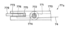
- 230000002452 interceptive effect Effects 0.000 description 2
- 238000000034 method Methods 0.000 description 2
- 230000001105 regulatory effect Effects 0.000 description 2
- 238000004891 communication Methods 0.000 description 1
- 230000000694 effects Effects 0.000 description 1
- 238000001125 extrusion Methods 0.000 description 1
- 210000000232 gallbladder Anatomy 0.000 description 1
- 238000001356 surgical procedure Methods 0.000 description 1
Images










Landscapes
- Surgical Instruments (AREA)
Description
【産業上の利用分野】
本発明は、主に腹腔鏡下手術に用いられる縫合・結紮器に関するものである。
【0002】
【従来の技術】
近年、例えば虫垂や胆嚢の切除術等において、従来の開腹手術に代わり、非開腹で行う腹腔鏡下手術が注目されている。この腹腔鏡下手術は、複数本のトロカール管と呼ばれる連通管を腹壁を貫通して腹腔内に挿入、固定し、一本のトロカール管から挿入した小型カメラ(内視鏡)によって腹腔内をモニターしつつ、他のトロカール管より挿入された鉗子、鋏、メス、持針器等の器具によって、モニター画像を見ながら腹腔内で手術を行うものである。
【0003】
ところで、現在では、腹腔鏡下手術専用の縫合器や結紮器が未だ開発されていないため、前記腹腔鏡下手術において生体組織を縫合する場合には、術者は、一般の持針器を用いて円弧状に湾曲した針を把持し、縫合するしかなく、縫合に手間と時間がかかっていた。
【0004】
さらに、縫合後に縫合糸を結紮する場合には、生体組織から出た糸を鉗子等を用いてトロカール管より体外へ一旦引き出し、体外で結び目を形成した後、再度糸をトロカール管内を通して腹腔内に戻し、糸を緊張させて結び目を縛ることにより行われており、縫合と同様に、手間と時間がかかっていた。
【0005】
【発明が解決しようとする課題】
本発明の目的は、1つの器具で縫合と結紮とを行うことができ、操作性に優れた縫合・結紮器を提供することにある。
【0006】
【課題を解決するための手段】
このような目的は、下記(1)〜(8)の本発明により達成される。
【0007】
(1) 中空の長尺な挿入管と、該挿入管の先端側に設けられた先端直線部と、該先端直線部の先端に接続された先端折り返し部と、前記先端折り返し部の先端に接続され、後端方向に延接された、先端に糸が突出可能な挿通孔が形成されている中空の針部とを有する全体が前記糸挿入用の中空の管状体によって構成された針棒と、
長尺の挿入部と、前記挿入部の先端に形成された先端湾曲部と、前記先端湾曲部の先端に接続された案内部と、前記針棒が通過できる開放部を有する湾曲形状に形成され、前記湾曲形状で囲まれた内側に形成され、前記針棒の前記先端折り返し部と前記針部が通過し前記針棒を外し得る通過部を有する結び目形成部と、前記結び目形成部の一端に設けられ前記糸を把持する第1の糸把持手段および前記開放部を前記針棒が通過するときだけ第1の糸把持手段に代わって前記糸を把持する第2の糸把持手段を有する長尺の糸把持装置と、
からなり、
前記結び目形成部の先端外側に前記先端折り返し部を介して前記結び目形成部の上側に前記針部、その下側に前記針棒の前記先端直線部、および前記結び目形成部の後端側上側に前記針棒を位置させることができることによって、前記針棒を前記通過部から外すとき前記糸は前記結び目形成部の上側から外側を通って下側にまわり込み、下側から前記通過部内を通って前記結び目形成部の上側に達することができることを特徴とする縫合・結紮器。
【0008】
(2) 前記第1の糸把持手段は、前記結び目形成部の開放端部に設けられた第1のチャックとこれを操作する第1のチャック操作手段とからなり、前記第2の糸把持手段は、前記第1のチャックより先端側に設置された第2のチャックとこれを操作する第2のチャック操作手段とから構成されている上記(1)に記載の縫合・結紮器。
【0009】
(3) 前記第2のチャックは、前記第1のチャックに対し、接近・離間するよう相対的に移動可能に設置され、前記相対的移動により前記第1のチャックまたは前記第2のチャックの一方に把持した糸を他方に持ち替え可能とした上記(2)に記載の縫合・結紮器。
【0010】
(4) 第1のチャック操作手段および第2のチャック操作手段は、前記第1のチャックおよび前記第2のチャックをそれぞれ独立して開閉操作するものである上記(2)または(3)に記載の縫合・結紮器。
【0011】
(5) 前記第1のチャック操作手段および前記第2のチャック操作手段は、それぞれ、前記第1のチャックおよび前記第2のチャックを閉じた状態で維持するロック手段を有する上記(4)に記載の縫合・結紮器。
【0012】
(6) 前記糸把持装置は、前記針棒との干渉を回避するために、その前記結び目形成部に形成された糸把持装置側逃げ部を有し、前記針棒は、前記糸把持手段と前記針棒との干渉を回避するために、前記針棒に形成された針側逃げ部を有している上記(1)ないし(5)のいずれかに記載の縫合・結紮器。
【0013】
(7) 前記糸把持装置側逃げ部は、互いに逆方向へ湾曲する一対の湾曲部を連結してなるものである上記(6)に記載の縫合・結紮器。
【0014】
(8) 前記針棒に対して前記糸を進退させる糸操作手段を有する上記(1)ないし(7)のいずれかに記載の縫合・結紮器。
【0015】
【実施例】
以下、本発明の縫合・結紮器を添付図面に示す好適実施例に基づいて詳細に説明する。
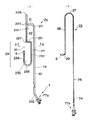
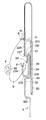
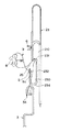
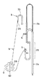
図1(A)は、本発明の第1実施例の縫合・結紮器1の備える糸把持装置2の平面図、図1(B)は、同じく針棒3の平面図である。なお、以下の説明では、図1、図2、図8ないし図18および図20ないし図26において、下側を「後端」、上側を「先端」といい、先端側へ移動することを「前進」、後端側へ移動することを「後退」といい、図面の紙面に対して手前側を「上側」、奥側を「下側」と表現する。
【0016】
図1に示される縫合・結紮器1は、腹腔鏡下手術に用いられる縫合・結紮器であって、腹壁を貫通して設置され、腹腔と体外とを連通させる連通管であるトロカール管(図示せず)内に挿入して使用されるものである。
この縫合・結紮器1の第1実施例は、図1および図2に示されているように、糸把持機構(糸把持装置)2と、針棒3とを有している。そして、糸把持機構2は、操作外管2aと、操作内管2bとを備えている。以下、これらについて、順次説明する。
【0017】
図2(A)に示されているように、操作外管2aは、全体が管状体によって構成されており、トロカール管内を挿通する長尺の挿入部20と、挿入部20の後端に接続され、第1のチャック操作手段7を構成するワイヤー牽引手段77aと、挿入部20の先端に形成された先端湾曲部21と、先端湾曲部21の先端部に接続され、挿入部20に平行に設けられている案内部22と、開放部25を有する湾曲形状の結び目形成部23と、結び目形成部23の一端に設けられている第1のチャック5とを有している。
【0018】
全体が管状体で構成されている操作外管2aは、挿入部20、先端湾曲部21、案内部22、結び目形成部23を有し、それらの内腔は、全てつながっている。
挿入部20は、トロカール管内を挿通し、後端のワイヤー牽引手段77が体外に突出した状態で、先端の結び目形成部23が体腔内に完全に突出する程度の長さを有し、具体的には、成人の手術に使用されるもので、例えば25〜45mm程度の長さを有している。そして、挿入部20の先端と後端には、内腔に連通する先端開口部201と後端開口部202がそれぞれ形成されている。また、後端には、ワイヤー牽引手段77aが挿入部20に対して屈曲した状態で接続されている。
【0019】
案内部22は、先端湾曲部21の接続部分よりも、さらに先端方向に突出して設けられており、その後端には結び目形成部23が接続されている。案内部22は、先端と後端に、内腔に連通する先端側開口部226と後端側開口部227とをそれぞれ有しており、さらに挿入部20に対して反対側の側面には、軸方向に形成されたスリット225が設けられている。このスリット225の後端は、後端側開口部227に接続され、開放された状態となっている。
【0020】
上記挿入部20と先端湾曲部21と案内部22とによって囲まれた部分には、空間210が形成される。
結び目形成部23は、一端が案内部22の後端に接続された糸把持装置側逃げ部231(以下「逃げ部231」と称する)と、該逃げ部231の他端に、先端が接続された直線部232と、直線部232の後端に一端が接続された湾曲部233と、湾曲部233の他端から先端方向へ向けて延出している開放端部234とを有している。これらの構成部は、各部が連続して形成され、先端側が逃げ部231、後端側が湾曲部233となるように、全体として先端から後端方向へ向けて細長い湾曲を形成し、逃げ部231と案内部22との間の接続部分と、開放端部234の先端との間に開放部25を有する一部が開放された湾曲形状となっている。
【0021】
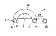
また、挿入部20、先端湾曲部21、案内部22および逃げ部231以外の結び目形成部23の構成部分は、ほぼ同一平面内に位置するように配置され、図3に示されているように、逃げ部231は、上記他の構成部に対して上側に半円状に湾曲した形状となっている。
以上のように構成された湾曲形状の結び目形成部23は、各構成部分で囲まれた内側に通過部230を形成する。この通過部230は、後述する針棒3の先端折り返し部33や針部34が通過し得る程度の広さとなっている。さらに、直線部232と挿入部20との間には、後述する針棒3の先端直線部36が通過し得る程度の十分な広さを有する隙間24が形成されている。
【0022】
第1のチャック5は、開放端部234の先端に設けられており、糸9を把持するための機構である。第1のチャック5の開閉は第1のチャック操作手段7によって体外から遠隔操作される。この第1のチャック5と第1のチャック操作手段7とによって第1の糸把持手段が構成されている。
【0023】
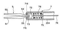
以下、第1のチャック5および第1のチャック操作手段7について説明する。図4および図5は、第1のチャック5および第1のチャック操作手段7の一部を示すもので、第1のチャック5の取り付け部分の部分断面側面図である。
【0024】
第1のチャック5は、一対の開閉可能な可動挟持片51、52で構成されており、両可動挟持片51、52は、それぞれその基端部において、摺動部材72に対しピン73により回動可能に支持されている。また、両可動挟持片51、52は、例えば図示しないバネにより、互いに開く方向に付勢されている。
【0025】
摺動部材72は、中空管である開放端部234の先端部に、軸方向に摺動可能に収納されている。摺動部材72の基端には、第1のチャック5を開閉するための牽引用ワイヤー74の先端が固着されている。また、開放端部234の内側に突出形成されたフランジ75と、摺動部材72との間には、コイルバネ76が圧縮状態で収納されている。このコイルバネ76により、摺動部材72は、先端側へ付勢され、開放端部234の先端壁の内面に当接する。
【0026】
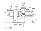
ワイヤー74は、開放端部234内を通り、結び目形成部23、案内部22、先端湾曲部21、挿入部20の各内腔内を通過して、挿入部20の後端部に設置されたワイヤー牽引手段77aに接続されている。ワイヤー牽引手段77aは、図6および図7に示されているように、挿入部20の後端に、一体として構成されている本体770と、巻き取り軸774と、ロック部材777とを有している。
【0027】
本体770内には、挿入部20の内腔と連通しているワイヤー挿通部771が、後端には規制溝773が、側面には巻き取り軸774を回動自在に軸支する孔772が形成されている。孔772内を挿通する巻き取り軸774は、ワイヤー挿通部771内に露出し、該ワイヤー挿通部771内においてワイヤー74が巻き付けられている。本体770の外側に突出した巻き取り軸774の一端には、アーム775が軸方向に対して直角に接続されており、そのアーム775の先端にはピン776を介してロック部材777の一端が回動自在に接続されている。
【0028】
ロック部材777の他端には、つまみ778が直角に形成されている。図6の想像線で示されているように、ロック部材777とアーム775とが一直線となる状態にロック部材777を回転させ、つまみ778を持って巻き取り軸774を回転させることができる。ワイヤー74を巻き取ることによってワイヤー74を牽引し、逆の方向に回転させることによってワイヤー74を緩めることができる。また、ロック部材777をピン776を中心として回転させて、規制溝773内に納めることによって(図6中実線で示す)、巻き取り軸774の回転を規制する。
【0029】
巻き取り軸774を回転させてワイヤー74を緩めることによって、ワイヤー74にはほとんど張力が作用せず、よって、図4に示すように、摺動部材72は、コイルバネ76の付勢力により先端側へ位置し、第1のチャック5の両可動挟持片51、52は、開いた状態となる。
【0030】
また、巻き取り軸774を巻き取り方向へ回転させて、ワイヤー74を後端方向へ牽引すると、図5に示されるように、摺動部材72は、コイルバネ76の付勢力に抗して後退し、第1のチャック5の両可動挟持片51、52も同様に後退する。この移動に伴い、可動挟持片51、52の基端部外面にそれぞれ形成されたテーパ部53、54が、開放端部234の先端壁の端面715に当接し、規制されて、第1のチャック5の両可動挟持片51、52は、閉じる。このとき、ロック部材777を規制溝773内へ収納してしまえば、巻き取り軸774の回動は、ロックされているので、第1のチャック5は閉じた状態を維持する。このロック部材777と、規制溝773とによってロック手段が構成されている。
【0031】
第1のチャック5についての摺動部材72、ピン73、ワイヤー74、フランジ75、コイルバネ76およびワイヤー牽引手段77aにより、第1のチャック5を遠隔操作する第1のチャック操作手段7が構成される。
【0032】
次に、操作内管2bの構成について説明する。図1(A)および図2(B)に示されているように、操作内管2bは、全体が管状体によって構成されており、操作外管2aの挿入部20内を挿通する操作側挿通管26と、操作側挿通管26の後端に接続され第2のチャック操作手段を構成するワイヤー牽引手段77bと、操作側挿通管26の先端に形成された湾曲部27と、湾曲部27の先端に接続され、操作外管2aの案内部22内を挿通するチャック側挿通管28と、チャック側挿通管28の先端部に形成された屈曲部29と、屈曲部29の先端に設けられた第2のチャック6とを有している。全体が管状体で構成されている操作内管2bは、操作側挿通管26、湾曲部27、チャック側挿通管28および屈曲部29を有し、それらの内腔が全てつながって構成されている。
【0033】
図1(A)に示されているように、操作側挿通管26は、操作外管2aの挿入部20内を軸方向移動自在に挿通しており、後端は後端開口部202から、先端は先端開口部201から操作外管2aの外側へ突出している。また、チャック側挿通管28は、操作外管2aの案内部22内を軸方向移動自在に挿通しており、先端側開口部226から案内部22内へ挿入されている。屈曲部29はスリット225から外側へ突出しており、その先端に設けられた第2のチャック6は、案内部22や操作側挿通管26に対してほぼ直角な向きに設けられている。
【0034】
また、操作側挿通管26の後端には、第2のチャック操作手段を構成するワイヤー牽引手段77bが接続されている。この第2のチャック6および第2のチャック操作手段は、上記第1のチャック5および第1のチャック操作手段7と同様に構成されているので、詳しい説明は省略する。この第2のチャック6および第2のチャック操作手段によって第2の糸把持手段が構成されている。また、ワイヤー74は全体を構成する管状体の内腔を挿通している。
【0035】
操作内管2bは、操作外管2aに対して移動自在となっており、操作外管2aに対して前進させることによって、第2のチャック6は、案内部22のスリット225内の待機位置へ移動し、後退させることによって、第2のチャック6は、後端方向へ移動し、案内部22の後端側開口部227から後端方向へ突出して、第1のチャック5に近接する位置(糸持ち替え位置)まで移動する構成となっている。
【0036】
次に、図1(B)に基づいて、針棒3の構成について詳説する。針棒3は、全体が管状体によって構成されており、トロカール管内を挿通する長尺の挿入管31と、挿入管31の先端部近傍に形成された針側逃げ部32と、針側逃げ部32の先端側に接続された先端直線部36と、さらに先端直線部36の先端に接続された先端折り返し部33と、先端折り返し部33の先端に接続され、挿入管31の後端方向へ延設された中空の針部34と、挿入管31の後端に接続された糸操作手段4とを有している。
【0037】
全体が中空の管状体で構成されている針棒3は、挿入管31、針側逃げ部32、先端直線部36、先端折り返し部33、針部34を有し、それらの内腔が全てつながっている。そして、針部34の先端部には糸挿通孔35が形成され、上記内腔と連通している。
【0038】
糸操作手段4の構成は、前述のワイヤー牽引手段77a、77bと同様の構成であり、巻き取り軸には糸9が巻き付けられている。糸9は、針棒3全体を構成する管状体の内腔を挿通し、糸9の先端は、針部34先端の糸挿通孔35の近傍に位置している。なお、針棒3の内径d1 、糸の外径をd2 とした時、d1 /d2 は、1.5〜3.0程度、特に2.0〜2.5程度であるのが好ましい。これにより、糸の押し出しがより円滑に行われる。
【0039】
挿入管31は、トロカール管内を挿通し、後端の糸操作手段4が体外に突出した状態で、先端部分やその後端側の針側逃げ部32が体腔内に完全に突出する程度の長さを有している。針側逃げ部32は、4つの屈曲部によって構成され、先端側のクランク部321と、後端側のクランク部322とから構成されている。
【0040】
先端側クランク部321と後端側クランク部322の距離は、操作外管2aの湾曲部233の後端位置から開放端部234の第1のチャック5の先端までの距離よりも長く形成されている。また、先端側クランク部321から、先端折り返し部33の内側頂点部までの距離は、操作外管2aの逃げ部231から湾曲部233の後端位置までの距離よりも長く形成されている。針側逃げ部32の各屈曲部は、図示されているように、丸みを帯びている(Rが形成されている)のが好ましい。これにより糸の進退がより円滑に行われる。
【0041】
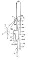
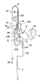
以上のように構成された縫合・結紮器1の操作手順を図8〜図18に基づいて説明する。図8は、体腔内に挿入された縫合・結紮器1の使用開始状態を示すもので、先端部分の平面図である。
【0042】
[1] 図8(A)に示されているように、糸把持機構2に針棒3を重ね合わせ、針部34の先端が第1のチャック5の先端側に対向する位置であって、先端直線部36が逃げ部231の内側を通過し、針棒3の他の部分が糸把持機構2の上側に位置するような状態、即ち糸把持機構2に対して針棒3を結び目形成位置に設定して、体腔内へ挿入する。この状態では、逃げ部231が上側に湾曲しているため、糸把持機構2と針棒3は互いに干渉することはない。
【0043】
[2] 図8(B)に示されているように、針棒3の針部34で縫合する生体組織を穿刺し、針棒3を後端方向へ引っ張りながら先端と糸挿通孔35が生体組織から突出した状態とし、必要であれば糸把持機構2を若干動かして、針部34の先端に第1のチャック5が近接した状態とする。
【0044】
[3] 図9(A)に示されているように、糸操作手段4を操作して糸挿通孔35から糸9の先端91を突出させるとともに、第1のワイヤー牽引手段77aを操作してチャック5を開かせる。
【0045】
[4] 図9(B)に示されているように、第1のワイヤー牽引手段77aを操作して第1のチャック5を閉じ、針部34の針挿通孔35から突出した糸先端91を把持し、その後、針部34を生体組織から引き抜く。これにより、生体組織には糸9が通され、糸挿通孔35からは順次糸が繰り出される。糸操作手段4は、糸の繰り出しが可能となるように、ロック手段のロック状態を解除(図6想像線の状態)しておく。
【0046】
[5] 図9(B)から図10(A)に示されているように、針部34が上側に位置するように、針棒3を例えば略90°回転させ、針部34を空間210を通してから糸把持機構2の外側(図中左側)に移動させる。そして、先端側クランク部321が開放部25を通過するように針棒3を操作して、通過部230内から完全に針棒3を外す。このような操作によって、糸9は、図10(A)に示されているように、結び目形成部23の上側から外側を通って下側にまわり込み、下側から通過部230内を通って結び目形成部23の上側に達し、針棒3の糸挿通孔35に到達するような状態となっている。
【0047】
[6] 図10(A)に示されているような状態から、結び目形成部23に巻き付けられている糸9を、糸把持機構2を移動させる等して、逃げ部231から直線部232、湾曲部233、開放端部234へと順次移動させ、結び目形成部23から外すと、図10(B)に示されているような結び目92が形成される。
このように、1重の結び目を形成する場合には、第2の糸把持手段や針側逃げ部32はなくてもよい。この後、糸把持機構2を前進させるとともに、針棒3を後退させるか、または糸操作手段4で糸9を巻き取ることにより、結び目92を緊締する。
【0048】
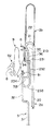
[7] 図11に示されているように、第2のワイヤー牽引手段77bを操作して、第2のチャック6を開かせるとともに、操作内管2bを後退させて第2のチャック6を第1のチャック5に接近させる。再度第2のワイヤー牽引手段77bを操作して、第1のチャック5が把持している糸先端91を、第2のチャック6で把持し、第1のワイヤー牽引手段77aを操作して第1のチャック5を開かせ、糸先端91を第1のチャック5から第2のチャック6へ持ち替えさせる。
【0049】
[8] 図12に示されているように、操作内管2bを前進させて糸先端91を把持した第2のチャック6を案内部22の待機位置へ移動させる。そして、針棒3の針部34が上側に位置するように針棒3を例えば略90°回転させて、先端直線部36を操作外管2aの隙間24を通し、また先端折り返し部33を空間210内へ移動させながら、先端直線部36を操作外管2aの下側へ移動させる。
【0050】
[9] 図13に示されているように、上記操作の結果、針部34以外の先端直線部36および針側逃げ部32は、結び目形成部23の下側に位置する。また、先端折り返し部33は、糸把持機構2の下側から空間210を通って、上側へ突出している。
【0051】
[10] 針側逃げ部32が結び目形成部23の下側に位置した上記[9]の状態のまま、針棒3を前進させて、針側逃げ部32内、即ち先端側クランク部321と後端側クランク部322の間に、結び目形成部23の開口端部234や湾曲部233が位置するように移動させる。
【0052】
[11] 上記[10]の状態で、先端側クランク部321が開口部25内を通過するように、針棒3を糸把持機構2の下側から上側へ移動させる。ここで、針棒3側に逃げ部32が形成されているため、相互に干渉することなく容易に針棒3を糸把持機構2の下側から上側に移動させることが可能となる。この移動によって、先端直線部36は、逃げ部231内へ移動する。図15に示されているように、針側逃げ部32が湾曲部233や開放端部234の上側に位置する状態で、操作内管2bを後退させ、第2のチャック6を第1のチャック5に接近させる。
【0053】
[12] 第1のワイヤー牽引手段77aを操作して、第1のチャック5を閉じて糸先端91を把持させ、第2のワイヤー牽引手段77bを操作して、第2のチャック6を開かせる。糸先端91の持ち替えを完了した後、操作内管2bを前進させて第2のチャック6を案内部22の先端部に移動させる。
【0054】
[13] 図16から図17に示されているように、針部34が上側に位置するように、針棒3を例えば略90°回転させ、針部34を空間210を通して案内部22の下側をくぐらせ、糸把持機構2の外側(図中左側)に移動させる。そして、先端側クランク部321が開放部25を通過するように針棒3を操作して、通過部230内から完全に針棒3を外す。このような操作によって、糸9は、図17に示されているように、上側から結び目形成部23の外側を通って下側にまわり込み、下側から通過部230を通って結び目形成部23の上側に達し、針棒3の糸挿通孔35に到達するような状態となっている。
【0055】
[14] 図17に示されているような状態から、結び目形成部23に巻き付けられている糸9を、糸把持機構2を移動させる等して、逃げ部231から直線部232、湾曲部233、開放端部234へと順次移動させ、結び目形成部23から外すと、図18に示されているような第2番目の結び目93が形成される。この結び目93は、結び目92と同方向の結び目である。さらに、針棒3を前進させ、糸把持機構2を後退あるいは糸9の巻き取りにより結び目93を緊締する。
以上ような[7]〜[14]の操作を繰り返すことによって3重以上の結び目を作ることもできる。
【0056】
次に、本発明の他の実施例について説明する。図19は、第2実施例の縫合・結紮器の操作外管の横断面図である。この第2実施例の縫合・結紮器は、互いに逆向きの2重の結び目を形成することができるものであり、逃げ部231の形状が、上側と下側とにそれぞれ湾曲突出した湾曲部によってS字状に構成されている。即ち、上逃げ部231aと下逃げ部231bとが連結された構成となっている。
【0057】
他の部分の構成は、既述の実施例と同一であるので説明は省略する。以上のように構成された縫合・結紮器1の他の実施例について、その作用を図20〜図26(A)に基づいて説明する。なお、第1番目の結び目92を形成する作用は、既述の実施例と同様であるため省略するが、操作外管2a側の逃げ部は、上逃げ部231aが用いられる。つまり、上記実施例の作用において、作用の[1]〜[7]までは同様の作用となるので省略する。以下、第2番目の結び目93を形成する作用について説明する。
【0058】
[8’] 糸把持機構2を略180°回転させて裏返しの状態とし、針棒3も同様に裏返しとする。そして、操作内管2bを前進させて、糸先端91を把持している第2のチャック6を案内部22の先端部分へ移動させた後、針棒3の針部34が上側に位置するように針棒3を略90°回転させて、先端直線部36を操作外管2aの隙間24を通し、また先端折り返し部33を空間210内へ移動させながら、先端直線部36を操作外管2aの下側へ移動させる。
【0059】
[9’] 図21に示されているように、上記操作の結果、針部34以外の先端直線部36および針側逃げ部32は、結び目形成部23の下側に位置する。そしてこの時、先端直線部36を下逃げ部231bの内側に位置させる。この時、先端折り返し部33は、糸把持機構2の下側から空間210を通って、上側へ突出している。
【0060】
[10’] 図22に示されているように、針側逃げ部32が結び目形成部23の下側に位置した上記[9’]の状態のまま、針棒3を前進させて、針側逃げ部32内、即ち先端側クランク部321と後端側クランク部322の間に、結び目形成部23の開口端部234や湾曲部233が位置するように移動させる。
【0061】
[11’] 上記[10’]の状態で、先端側クランク部321が開口部25内を通過するように、針棒3を糸把持機構2の下側から上側へ移動させる。ここで、針棒3側に逃げ部32が形成されているため、相互に干渉することなく、容易に針棒3を糸把持機構2の下側から上側に移動させることが可能となる。この移動によって、先端直線部36は、下逃げ部231b内へ移動する。図23に示されているように、針側逃げ部32が湾曲部233や開放端部234の上側に位置する状態で、操作内管2bを後退させ、第2のチャック6を第1のチャック5に接近させる。第1のワイヤー牽引手段77aと第2のワイヤー牽引手段77bをこの順で操作し、第1のチャック5を閉じ、第2のチャック6を開いて糸先端91を持ち替える。
【0062】
[12’] 図24から図25に示されているように、針部34が上側に位置するように、針棒3を略90°回転させ、針部34を空間210を通して案内部22の下側をくぐらせ、糸把持機構2の外側(図25中右側)に移動させる。そして、先端側クランク部321が開放部25を通過するように針棒3を操作して、通過部230内から完全に針棒3を外す。このような操作によって、糸9は、図25に示されているように、上側から結び目形成部23の外側を通って下側にまわり込み、下側から通過部230を通って結び目形成部23の上側に達し、針棒3の糸挿通孔35に到達するような状態となる。
【0063】
[13’] 図25に示されているような状態から、結び目形成部23に巻き付けられている糸9を、糸把持機構2を移動させる等して、逃げ部231から直線部232、湾曲部233、開放端部234へと順次移動させ、結び目形成部23から外すと、図26に示されているような第2番目の結び目93が形成される。この結び目93は、第1番目の結び目92に対して糸9の結び合わせ方向が逆となり、特に解けにくい結び目となる。さらに、前記と同様にして結び目93を緊締する。
上記2つの実施例における操作手順は、上記内容に限定されるものではなく、種々の変更が可能である。
【0064】
以上のような実施例の他、例えば針棒3の構成を、図27に示されているように、針側逃げ部32を矩形状とせず、円弧状や楕円状とすることもできる。
また、操作外管2a側に形成されている逃げ部231を、結び目形成部23の湾曲部233に設け、湾曲方向を下側としてもよい。あるいは、操作外管2a側には逃げ部231を設けず、針棒3側の先端直線部36の位置に湾曲した逃げ部を形成した構成としてもよい。
【0065】
また結び目形成部23の形状なども上記形状に限定されるものではなく、チャックの構成およびチャック操作手段の構成なども、それぞれ同様の機能を有する他の任意の構成と置換することが可能である。なお、本発明の縫合・結紮器は、腹腔鏡下手術に用いられるものに限定されない。
【0066】
【発明の効果】
以上説明したように、本発明の縫合・結紮器によれば、1つの器具で縫合と結紮とを行うことができ、特に、逃げ部の形成によって、糸把持機構と針棒とが操作中に干渉しないので操作が容易となり、腹腔内等で縫合、結紮を迅速かつ確実に完了することができる。そのため、患者への負担が減少し、安全性も高まる。
【0067】
また、糸把持手段を2つ設け、糸の持ち替えを可能とした場合には、第2番目以降の結び目の形成が連続して可能となり、さらに迅速な縫合、結紮が可能となる。
また、2つのチャックを相対的に移動可能とし、容易に糸の持ち替えを可能とした場合には、把持している糸を落とすことなく糸の受け渡しができ、より一層迅速な縫合、結紮ができる。
【0068】
また、2つチャックを独立して操作するチャック操作手段を設けた場合には、チャックの操作が体外から容易に行うことができる。
さらに、チャック操作手段にロック手段を設けた場合には、糸の把持状態を容易に維持させることができ、他の操作を行うための余裕ができ、操作をより容易に行うことができる。
【0069】
針側逃げ部を形成した場合には、第2番目以降の結び目を形成する場合において、糸把持機構と針棒との相互間の干渉を回避して、さらに容易確実に結び目の形成ができる。
ここで、糸把持装置側逃げ部の形状を互いに逆方向へ湾曲した構成とすると、第2番目の結び目の結び方を第1番目の結び目の逆向きとすることができ、外科用結紮に適した、ほどけにくい結び目の形成が可能となる。
【0070】
また、糸操作手段を設けることにより、糸の進退操作が可能となり、容易に糸把持手段へ糸を把持させることができ、さらに、糸の張力を調節することが可能となるため、糸を引っ張って、結び目を確実に形成させることができる。
【図面の簡単な説明】
【図1】本発明の第1実施例の平面図である。
【図2】本発明における第1実施例の糸把持装置の平面図である。
【図3】図2に示された第1実施例のA−A線断面図である。
【図4】第1のチャックおよび第2のチャックの構成を示す断面図である。
【図5】第1のチャックおよび第2のチャックの構成を示す断面図である。
【図6】ワイヤー牽引手段の構成を示す断面側面図である。
【図7】ワイヤー牽引手段の構成を示す平面図である。
【図8】本発明の第1実施例の操作状態を示す平面図である。
【図9】本発明の第1実施例の操作状態を示す平面図である。
【図10】本発明の第1実施例の操作状態を示す平面図である。
【図11】本発明の第1実施例の操作状態を示す平面図である。
【図12】本発明の第1実施例の操作状態を示す平面図である。
【図13】本発明の第1実施例の操作状態を示す平面図である。
【図14】本発明の第1実施例の操作状態を示す平面図である。
【図15】本発明の第1実施例の操作状態を示す平面図である。
【図16】本発明の第1実施例の操作状態を示す平面図である。
【図17】本発明の第1実施例の操作状態を示す平面図である。
【図18】本発明の第1実施例の操作状態を示す平面図である。
【図19】第2実施例の操作外管の横断面図である。
【図20】本発明の第2実施例の操作状態を示す平面図である。
【図21】本発明の第2実施例の操作状態を示す平面図である。
【図22】本発明の第2実施例の操作状態を示す平面図である。
【図23】本発明の第2実施例の操作状態を示す平面図である。
【図24】本発明の第2実施例の操作状態を示す平面図である。
【図25】本発明の第2実施例の操作状態を示す平面図である。
【図26】本発明の第2実施例の操作状態を示す平面図である。
【図27】針棒の他の実施例を示す平面図である。
【符号の説明】
1 縫合・結紮器
2 糸把持機構
2a 操作外管
20 挿入部
201 先端開口部
202 後端開口部
21 先端湾曲部
210 空間
22 案内部
225 スリット
226 先端側開口部
227 後端側開口部
23 結び目形成部
230 通過部
231 逃げ部
231a 上逃げ部
231b 下逃げ部
232 直線部
233 湾曲部
234 開放端部
24 隙間
25 開放部
2b 操作内管
26 (操作側)挿通管
27 湾曲部
28 (チャック側)挿通管
29 屈曲部
3 針棒
31 挿入管
32 針側逃げ部
321 先端側クランク部
322 後端側クランク部
33 先端折り返し部
34 針部
35 糸挿通孔
36 先端直線部
4 糸操作手段
5 第1のチャック
51、52 可動挟持片
53、54 テーパ部
6 第2のチャック
7 チャック操作手段
715 先端壁の端面
72 摺動部材
73 ピン
74 ワイヤー
75 フランジ
76 コイルバネ
77 ワイヤー牽引手段
770 本体
771 ワイヤー挿通部
772 孔
773 規制溝
774 巻き取り軸
775 アーム
776 ピン
777 ロック部材
778 つまみ
8 生体組織
9 糸
91 糸先端
92 第1番目の結び目
93 第2番目の結び目[Industrial application fields]
The present invention relates to a suture / ligator mainly used in laparoscopic surgery.
[0002]
[Prior art]
In recent years, for example, in laparotomy of the appendix or gallbladder, laparoscopic surgery that performs non-laparotomy has been attracting attention in place of conventional laparotomy. In this laparoscopic surgery, a plurality of communication tubes called trocar tubes are inserted and fixed in the abdominal cavity through the abdominal wall, and the abdominal cavity is monitored by a small camera (endoscope) inserted through a single trocar tube. However, the operation is performed in the abdominal cavity while viewing the monitor image with instruments such as forceps, scissors, scalpel and needle holder inserted from other trocar tubes.
[0003]
By the way, since a suture instrument and a ligator dedicated to laparoscopic surgery have not been developed at present, an operator uses a general needle holder when suturing a living tissue in the laparoscopic surgery. In other words, it was necessary to grasp and sew the needle curved in an arc shape, and it took time and effort to sew.
[0004]
Further, when ligating the suture after suturing, the thread from the living tissue is once pulled out of the trocar tube using forceps and the like, and after forming a knot outside the body, the thread is again passed into the abdominal cavity through the trocar tube. It was done by tying the thread back and tying the knot, which was time consuming and time consuming, as was the case with suturing.
[0005]
[Problems to be solved by the invention]
An object of the present invention is to provide a suturing / ligating device that can perform suturing and ligating with a single instrument and has excellent operability.
[0006]
[Means for Solving the Problems]
Such an object is achieved by the present inventions (1) to (8) below.
[0007]
(1) Hollow long insertion tube and tip of the insertion tube~ sideInA provided tip straight portion, a tip folded portion connected to the tip of the tip straight portion, connected to the tip of the tip folded portion, and extended in the rear end direction;tipInA hollow needle portion having an insertion hole through which a thread can protrudeThe whole was constituted by the hollow tubular body for thread insertionA needle bar,
A long insertion portion, a tip bending portion formed at the tip of the insertion portion, a guide portion connected to the tip of the tip bending portion, and the needle bar can pass through.Formed in a curved shape having an open part,Formed inside the curved shape,The needleThe tip folded portion and the needle portion of the barPassedNeedle barA knot forming part having a passing part that can be removed, andProvided at one end of the knot forming portion.Grip the threadFirstYarn gripping meansAnd second thread gripping means for gripping the thread instead of the first thread gripping means only when the needle bar passes through the opening.A long thread gripping device having,
Consists of
The needle part on the upper side of the knot forming part via the tip folding part on the outer side of the tip end of the knot forming part, the tip straight part of the needle bar on the lower side, and the rear end side upper side of the knot forming part By being able to position the needle bar, when the needle bar is removed from the passage portion, the thread passes from the upper side of the knot forming portion to the lower side and passes downward, and from the lower side through the passage portion. Can reach the upper side of the knot forming partSuture / ligator characterized by this.
[0008]
(2) saidFirstThe yarn gripping means includes a first chuck provided at an open end of the knot forming portion,Comprising a first chuck operating means for operating this.,The second thread gripping means includesA second chuck installed on the tip side of the first chuck;It is comprised from the 2nd chuck operation means which operates thisThe suturing / ligating apparatus according to (1) above.
[0009]
(3) The second chuck is disposed so as to be relatively movable so as to approach and separate from the first chuck, and one of the first chuck and the second chuck is moved by the relative movement. The suturing / ligating apparatus according to (2), wherein the thread gripped on the other side can be changed to the other.
[0010]
(4)The first chuck operation means and the second chuck operation means open and close the first chuck and the second chuck independently of each other.The suturing / ligating apparatus according to (2) or (3) above.
[0011]
(5) saidThe first chuck operation means and the second chuck operation means are respectivelyThe suturing / ligating apparatus according to (4), further including a lock unit that maintains the first chuck and the second chuck in a closed state.
[0012]
(6) The yarn gripping deviceIn order to avoid interference with the needle barIt has a thread gripping device side relief portion formed in the knot forming portion,The needle bar isAvoid interference between the thread gripping means and the needle barfor,The suturing / ligating apparatus according to any one of the above (1) to (5), which has a needle side relief portion formed on the needle bar.
[0013]
(7) The suture / ligator according to (6), wherein the thread gripping device side relief portion is formed by connecting a pair of curved portions that are curved in opposite directions.
[0014]
(8) The suturing / ligating apparatus according to any one of (1) to (7), further including a thread operation means for moving the thread forward and backward with respect to the needle bar.
[0015]
【Example】
Hereinafter, the suturing / ligating apparatus of the present invention will be described in detail based on a preferred embodiment shown in the accompanying drawings.
FIG. 1A is a plan view of a
[0016]
A suturing / ligating apparatus 1 shown in FIG. 1 is a suturing / ligating apparatus used for laparoscopic surgery, and is installed through the abdominal wall to communicate with the abdominal cavity and the outside of the body. (Not shown) to be used.
As shown in FIGS. 1 and 2, the first embodiment of the suturing / ligating device 1 includes a thread gripping mechanism (thread gripping device) 2 and a
[0017]
As shown in FIG. 2A, the operation
[0018]
The operation
The
[0019]
The
[0020]
A
The
[0021]
Further, the components of the
The curved
[0022]
The
[0023]
Hereinafter, the
[0024]
The
[0025]
The sliding
[0026]
The
[0027]
In the
[0028]
At the other end of the
[0029]
By rotating the take-up
[0030]
When the winding
[0031]
The first chuck operating means 7 for remotely operating the
[0032]
Next, the configuration of the operation
[0033]
As shown in FIG. 1 (A), the operation
[0034]
Further, a
[0035]
The operation
[0036]
Next, the configuration of the
[0037]
The
[0038]
The configuration of the yarn operating means 4 is the same as that of the
[0039]
The
[0040]
The distance between the front end side crank
[0041]
The operation procedure of the suturing / ligating apparatus 1 configured as described above will be described with reference to FIGS. FIG. 8 is a plan view of the distal end portion, showing the use start state of the suturing / ligating device 1 inserted into the body cavity.
[0042]
[1] As shown in FIG. 8A, the
[0043]
[2] As shown in FIG. 8B, the living body tissue to be sutured is punctured by the
[0044]
[3] As shown in FIG. 9 (A), the thread operating means 4 is operated to cause the
[0045]
[4] As shown in FIG. 9B, the first
[0046]
[5] As shown in FIGS. 9B to 10A, the
[0047]
[6] From the state as shown in FIG. 10A, the
Thus, when forming a single knot, there is no need for the second thread gripping means and the needle
[0048]
[7] As shown in FIG. 11, the second
[0049]
[8] As shown in FIG. 12, the operation
[0050]
[9] As shown in FIG. 13, as a result of the above operation, the tip
[0051]
[10] While the needle
[0052]
[11] In the state [10] above, the
[0053]
[12] The first
[0054]
[13] As shown in FIGS. 16 to 17, the
[0055]
[14] From the state as shown in FIG. 17, the
By repeating the operations [7] to [14] as described above, a triple or more knot can be formed.
[0056]
Next, another embodiment of the present invention will be described. FIG. 19 is a cross-sectional view of the operation outer tube of the suturing / ligating apparatus of the second embodiment. The suture / ligator of the second embodiment is capable of forming double knots that are opposite to each other, and the shape of the
[0057]
Since the configuration of the other parts is the same as that of the above-described embodiment, description thereof is omitted. The operation of another embodiment of the suturing / ligating apparatus 1 configured as described above will be described with reference to FIGS. Although the operation of forming the
[0058]
[8 '] The thread
[0059]
[9 ′] As shown in FIG. 21, as a result of the above operation, the tip
[0060]
[10 ′] As shown in FIG. 22, the
[0061]
[11 ′] In the state [10 ′], the
[0062]
[12 ′] As shown in FIGS. 24 to 25, the
[0063]
[13 ′] From the state as shown in FIG. 25, the
The operation procedures in the above two embodiments are not limited to the above contents, and various changes can be made.
[0064]
In addition to the embodiment described above, for example, as shown in FIG. 27, the
In addition, the
[0065]
Further, the shape of the
[0066]
【The invention's effect】
As described above, according to the suturing / ligating apparatus of the present invention, it is possible to perform suturing and ligating with one instrument, and in particular, the thread gripping mechanism and the needle bar are being operated by the formation of the relief portion. Since there is no interference, the operation becomes easy, and the suturing and ligation can be completed quickly and reliably in the abdominal cavity or the like. This reduces the burden on the patient and increases safety.
[0067]
Further, when two thread gripping means are provided so that the thread can be changed, the second and subsequent knots can be formed continuously, and more rapid stitching and ligation are possible.
In addition, when the two chucks can be moved relative to each other and the thread can be easily changed, the thread can be transferred without dropping the gripped thread, and more rapid stitching and ligation can be achieved. .
[0068]
Further, when the chuck operating means for operating the two chucks independently is provided, the chuck can be easily operated from outside the body.
Further, when the chuck operating means is provided with a lock means, the gripping state of the yarn can be easily maintained, there is a margin for performing other operations, and the operation can be performed more easily.
[0069]
When the needle-side relief portion is formed, when the second and subsequent knots are formed, the knots can be formed more easily and reliably by avoiding interference between the thread gripping mechanism and the needle bar.
Here, if the shape of the escape portion on the side of the thread gripping device is curved in opposite directions, the second knot can be knotted in the opposite direction, which is suitable for surgical ligation. This makes it possible to form knots that are difficult to unwind.
[0070]
Also, by providing the thread operating means, the thread can be advanced and retracted, the thread gripping means can be easily gripped, and the tension of the thread can be adjusted. Thus, the knot can be surely formed.
[Brief description of the drawings]
FIG. 1 is a plan view of a first embodiment of the present invention.
FIG. 2 is a plan view of the yarn gripping device according to the first embodiment of the present invention.
FIG. 3 is a cross-sectional view taken along line AA of the first embodiment shown in FIG.
FIG. 4 is a cross-sectional view showing configurations of a first chuck and a second chuck.
FIG. 5 is a cross-sectional view showing configurations of a first chuck and a second chuck.
FIG. 6 is a sectional side view showing the configuration of the wire pulling means.
FIG. 7 is a plan view showing the configuration of the wire pulling means.
FIG. 8 is a plan view showing an operation state of the first embodiment of the present invention.
FIG. 9 is a plan view showing an operation state of the first embodiment of the present invention.
FIG. 10 is a plan view showing an operation state of the first embodiment of the present invention.
FIG. 11 is a plan view showing an operation state of the first embodiment of the present invention.
FIG. 12 is a plan view showing an operation state of the first embodiment of the present invention.
FIG. 13 is a plan view showing an operation state of the first embodiment of the present invention.
FIG. 14 is a plan view showing an operation state of the first embodiment of the present invention.
FIG. 15 is a plan view showing an operation state of the first embodiment of the present invention.
FIG. 16 is a plan view showing an operation state of the first embodiment of the present invention.
FIG. 17 is a plan view showing an operation state of the first embodiment of the present invention.
FIG. 18 is a plan view showing an operation state of the first embodiment of the present invention.
FIG. 19 is a cross-sectional view of an operation outer tube of a second embodiment.
FIG. 20 is a plan view showing an operation state of the second embodiment of the present invention.
FIG. 21 is a plan view showing an operation state of the second embodiment of the present invention.
FIG. 22 is a plan view showing an operation state of the second embodiment of the present invention.
FIG. 23 is a plan view showing an operation state of the second embodiment of the present invention.
FIG. 24 is a plan view showing an operation state of the second embodiment of the present invention.
FIG. 25 is a plan view showing an operation state of the second embodiment of the present invention.
FIG. 26 is a plan view showing an operation state of the second embodiment of the present invention.
FIG. 27 is a plan view showing another embodiment of the needle bar.
[Explanation of symbols]
1 Suture / ligator
2 Yarn gripping mechanism
2a Operation outer tube
20 Insertion section
201 Tip opening
202 Rear end opening
21 Curved tip
210 space
22 Guide
225 slit
226 Tip side opening
227 Rear end side opening
23 Knot forming part
230 Passing part
231 Escape part
231a Upper clearance
231b Lower relief
232 Straight part
233 Curved part
234 Open end
24 Clearance
25 Opening part
2b Operation pipe
26 (Operating side) Insertion tube
27 Curved part
28 (Chuck side) insertion tube
29 Bending part
3 Needle bar
31 Insertion tube
32 Needle side relief
321 Front end crank part
322 Rear end side crank part
33 Tip folding part
34 Needle
35 Thread insertion hole
36 Straight end of tip
4 Yarn operation means
5 First chuck
51, 52 Movable clamping piece
53, 54 Taper
6 Second chuck
7 Chuck operation means
715 End face of tip wall
72 Sliding member
73 pin
74 wires
75 flange
76 Coil spring
77 Wire pulling means
770 body
771 Wire insertion part
772 holes
773 Regulating groove
774 Winding shaft
775 arm
776 pins
777 Lock member
778 knob
8 biological tissues
9 Yarn
91 Thread tip
92 First Knot
93 Second Knot
Claims (8)
長尺の挿入部と、前記挿入部の先端に形成された先端湾曲部と、前記先端湾曲部の先端に接続された案内部と、前記針棒が通過できる開放部を有する湾曲形状に形成され、前記湾曲形状で囲まれた内側に形成され、前記針棒の前記先端折り返し部と前記針部が通過し前記針棒を外し得る通過部を有する結び目形成部と、前記結び目形成部の一端に設けられ前記糸を把持する第1の糸把持手段および前記開放部を前記針棒が通過するときだけ第1の糸把持手段に代わって前記糸を把持する第2の糸把持手段を有する長尺の糸把持装置と、
からなり、
前記結び目形成部の先端外側に前記先端折り返し部を介して前記結び目形成部の上側に前記針部、その下側に前記針棒の前記先端直線部、および前記結び目形成部の後端側上側に前記針棒を位置させることができることによって、前記針棒を前記通過部から外すとき前記糸は前記結び目形成部の上側から外側を通って下側にまわり込み、下側から前記通過部内を通って前記結び目形成部の上側に達することができることを特徴とする縫合・結紮器。A hollow long insertion tube, a tip straight portion provided on the tip end side of the insertion tube, a tip folding portion connected to the tip of the tip straight portion, and a tip of the tip folding portion; A needle bar that is formed of a hollow tubular body for thread insertion, and has a hollow needle portion that extends in the end direction and has a hollow needle portion formed with an insertion hole through which a thread can protrude at the tip;
It is formed in a curved shape having a long insertion portion, a tip bending portion formed at the tip of the insertion portion, a guide portion connected to the tip of the tip bending portion, and an open portion through which the needle bar can pass. A knot forming portion formed on the inner side surrounded by the curved shape, and having a tip folding portion of the needle bar and a passing portion through which the needle portion can pass and the needle bar can be removed , and one end of the knot forming portion A first thread gripping means provided for gripping the thread and a second thread gripping means for gripping the thread instead of the first thread gripping means only when the needle bar passes through the opening portion. and the yarn gripping device,
Consists of
The needle part on the upper side of the knot forming part via the tip folding part on the outer side of the tip end of the knot forming part, the tip straight part of the needle bar on the lower side, and the rear end side upper side of the knot forming part By being able to position the needle bar, when the needle bar is removed from the passage portion, the thread passes from the upper side of the knot forming portion to the lower side and passes downward, and from the lower side through the passage portion. A suturing / ligating device characterized by being able to reach the upper side of the knot forming portion .
Priority Applications (1)
| Application Number | Priority Date | Filing Date | Title |
|---|---|---|---|
| JP07082995A JP3781451B2 (en) | 1995-03-03 | 1995-03-03 | Suture / ligator |
Applications Claiming Priority (1)
| Application Number | Priority Date | Filing Date | Title |
|---|---|---|---|
| JP07082995A JP3781451B2 (en) | 1995-03-03 | 1995-03-03 | Suture / ligator |
Publications (2)
| Publication Number | Publication Date |
|---|---|
| JPH08238250A JPH08238250A (en) | 1996-09-17 |
| JP3781451B2 true JP3781451B2 (en) | 2006-05-31 |
Family
ID=13442866
Family Applications (1)
| Application Number | Title | Priority Date | Filing Date |
|---|---|---|---|
| JP07082995A Expired - Fee Related JP3781451B2 (en) | 1995-03-03 | 1995-03-03 | Suture / ligator |
Country Status (1)
| Country | Link |
|---|---|
| JP (1) | JP3781451B2 (en) |
Families Citing this family (1)
| Publication number | Priority date | Publication date | Assignee | Title |
|---|---|---|---|---|
| US20070072466A1 (en) | 2005-09-27 | 2007-03-29 | Manabu Miyamoto | Instrument for endoscope |
-
1995
- 1995-03-03 JP JP07082995A patent/JP3781451B2/en not_active Expired - Fee Related
Also Published As
| Publication number | Publication date |
|---|---|
| JPH08238250A (en) | 1996-09-17 |
Similar Documents
| Publication | Publication Date | Title |
|---|---|---|
| US6554845B1 (en) | Suturing apparatus and method | |
| US5350385A (en) | Surgical stab wound closure device and method | |
| US5447512A (en) | Controller for intracorporeal knot tying apparatus | |
| US5152769A (en) | Apparatus for laparoscopic suturing with improved suture needle | |
| US5643292A (en) | Percutaneous suturing device | |
| JP4855405B2 (en) | Apparatus and method for minimally invasive suturing | |
| US6086601A (en) | Instrument and method for suturing anatomical tissue and tying suture material | |
| US9451947B2 (en) | Knot tying surgical needle driver | |
| JP2009247888A (en) | Medical treatment system | |
| JPH08215200A (en) | Suture seizure device and its seizure method | |
| WO2007037335A1 (en) | Suturing device | |
| JP5372301B1 (en) | Medical port | |
| US12150643B2 (en) | Endoscopic treatment device | |
| US12544060B2 (en) | System, apparatus, and method for suturing | |
| JP3781451B2 (en) | Suture / ligator | |
| JPH0654855A (en) | Needle holder for operation under endoscope, cartridge for ligature and suturing and ligating device for operation under endoscope consisting of combination thereof | |
| JPH08308847A (en) | Ligating tool | |
| JP4838946B2 (en) | Suture tool | |
| JP3327073B2 (en) | Ligation device | |
| JP3800648B2 (en) | Ligation device | |
| CN110099611B (en) | suture device | |
| JP3781450B2 (en) | Suture / ligator | |
| KR101667111B1 (en) | Continuous suturing apparatus for endoscopy and endoscopy having continuous suturing function | |
| JPH09262242A (en) | Needle carrier | |
| JP2004105326A (en) | Retractor |
Legal Events
| Date | Code | Title | Description |
|---|---|---|---|
| A977 | Report on retrieval |
Free format text: JAPANESE INTERMEDIATE CODE: A971007 Effective date: 20050330 |
|
| A131 | Notification of reasons for refusal |
Free format text: JAPANESE INTERMEDIATE CODE: A131 Effective date: 20050602 |
|
| A521 | Written amendment |
Free format text: JAPANESE INTERMEDIATE CODE: A523 Effective date: 20050726 |
|
| TRDD | Decision of grant or rejection written | ||
| A01 | Written decision to grant a patent or to grant a registration (utility model) |
Free format text: JAPANESE INTERMEDIATE CODE: A01 Effective date: 20060215 |
|
| A61 | First payment of annual fees (during grant procedure) |
Free format text: JAPANESE INTERMEDIATE CODE: A61 Effective date: 20060307 |
|
| R150 | Certificate of patent or registration of utility model |
Free format text: JAPANESE INTERMEDIATE CODE: R150 |
|
| LAPS | Cancellation because of no payment of annual fees |