JP3783706B2 - Stirling engine and hybrid system including the same - Google Patents
Stirling engine and hybrid system including the same Download PDFInfo
- Publication number
- JP3783706B2 JP3783706B2 JP2003343416A JP2003343416A JP3783706B2 JP 3783706 B2 JP3783706 B2 JP 3783706B2 JP 2003343416 A JP2003343416 A JP 2003343416A JP 2003343416 A JP2003343416 A JP 2003343416A JP 3783706 B2 JP3783706 B2 JP 3783706B2
- Authority
- JP
- Japan
- Prior art keywords
- piston
- stirling engine
- cylinder
- connecting rod
- approximate linear
- Prior art date
- Legal status (The legal status is an assumption and is not a legal conclusion. Google has not performed a legal analysis and makes no representation as to the accuracy of the status listed.)
- Expired - Fee Related
Links
Images





Classifications
-
- Y—GENERAL TAGGING OF NEW TECHNOLOGICAL DEVELOPMENTS; GENERAL TAGGING OF CROSS-SECTIONAL TECHNOLOGIES SPANNING OVER SEVERAL SECTIONS OF THE IPC; TECHNICAL SUBJECTS COVERED BY FORMER USPC CROSS-REFERENCE ART COLLECTIONS [XRACs] AND DIGESTS
- Y02—TECHNOLOGIES OR APPLICATIONS FOR MITIGATION OR ADAPTATION AGAINST CLIMATE CHANGE
- Y02E—REDUCTION OF GREENHOUSE GAS [GHG] EMISSIONS, RELATED TO ENERGY GENERATION, TRANSMISSION OR DISTRIBUTION
- Y02E20/00—Combustion technologies with mitigation potential
- Y02E20/16—Combined cycle power plant [CCPP], or combined cycle gas turbine [CCGT]
- Y02E20/18—Integrated gasification combined cycle [IGCC], e.g. combined with carbon capture and storage [CCS]
Landscapes
- Engine Equipment That Uses Special Cycles (AREA)
- Compressors, Vaccum Pumps And Other Relevant Systems (AREA)
Description
本発明は、スターリングエンジン及び及びそれを備えたハイブリッドシステムに関し、特に、摩擦損失を低減可能なスターリングエンジン及びそれを備えたハイブリッドシステムに関する。 The present invention relates to a Stirling engine and a hybrid system including the same, and more particularly to a Stirling engine capable of reducing friction loss and a hybrid system including the same.
スターリングエンジンは、高い熱効率が期待できる上に、作動流体を外から加熱する外燃機関であるために、熱源を問わず、ソーラー、地熱、排熱といった各種の低温度差代替エネルギーを活用でき、省エネルギーに役立つという利点がある。 The Stirling engine can be expected to have high thermal efficiency, and since it is an external combustion engine that heats the working fluid from the outside, it can utilize various low temperature difference alternative energy such as solar, geothermal, exhaust heat regardless of the heat source, It has the advantage of helping to save energy.
従来、図18に示すようなスターリングエンジンが知られている。機械室101には、高温側気筒102と低温側気筒103とが突設されており、高温側気筒102の上部には加熱器104が接続され、低温側気筒103には冷却器105が接続され、加熱器104及び冷却器105は、再生器106を介して互いに接続されている。高温側気筒102及び低温側気筒103には、それぞれ膨張ピストン107及び圧縮ピストン108が往復動可能に配設されており、両ピストン107,108はそれぞれコネクティングロッド109,110によってクランク軸111に連結され、両ピストン107,108が互いに所定位相差例えば90°をもって往復動するように構成されている。
Conventionally, a Stirling engine as shown in FIG. 18 is known. In the
高温側気筒102、低温側気筒103、加熱器104、冷却器105及び再生器106並びにそれらを配管中には、He、H2、あるいはN2等の作動流体が封入されており、高温側気筒102の上部の膨張空間及び低温側気筒103の上部の圧縮空間は、それぞれピストン107、108に装着されたピストンリング112、113によってシールされている。
A high
加熱器104で作動流体が熱源(図示せず)によって加熱されると、膨張して膨張ピストン107が圧下され、クランク軸111の回動が行われる。また、膨張ピストン107が上昇行程に移ると、作動流体は加熱器104を通過して再生器106に移送され、そこで再生器106内に充填されている蓄熱材に熱を与え、冷却器105へと流れて冷却され、圧縮ピストン108の上昇行程に伴って圧縮される。このようにして圧縮された作動流体は、逆に加熱器104側に流れ、その途中で再生器106内の蓄熱材から熱を奪いながら温度を上昇して、加熱器104へ流れ込み、そこで再び熱源によって加熱膨張せしめられる。
When the working fluid is heated by the
ところで、特開平4−311656号公報(特許文献1)には、ピストンピンをワットのZ形近似直線リンク機構により案内するスターリングエンジンが開示されている。 By the way, Japanese Patent Laid-Open No. 4-31656 (Patent Document 1) discloses a Stirling engine that guides a piston pin by a Watt Z-shaped approximate linear link mechanism.
また、特開2002−89985号公報(特許文献2)には、ピストンとシリンダとの間に気体軸受(ガスベアリング)を用いた技術が開示されている。即ち、特許文献2には、シリンダのガスベアリングパッドに形成されたオリフィスからピストンに向けて供給されたガスによりピストンに浮上力を生じさせ、ピストンとシリンダとの間を非接触状態、又は軽負荷状態にすることにより、摩擦力が無くなるか又は小さくなることが記載されている。 Japanese Patent Laid-Open No. 2002-89985 (Patent Document 2) discloses a technique using a gas bearing (gas bearing) between a piston and a cylinder. That is, in Patent Document 2, a floating force is generated in the piston by the gas supplied from the orifice formed in the gas bearing pad of the cylinder toward the piston, and the piston and the cylinder are in a non-contact state or light load. It is described that the frictional force disappears or becomes smaller by setting the state.
スターリングエンジンには、内部フリクションが大きいという問題がある。
スターリングエンジンの出力を確保するために、シリンダ内の作動流体を高圧化する必要がある。そのため、シールを強化する必要があり、特にピストンリングによるシールの強化は、フリクションの更なる増加を招く。フリクションが大きいため、十分な出力を確保するには、高熱源及び作動流体の高圧化が必要となる。また、ピストンリングの潤滑オイルが熱交換器に入り込み、熱交換器が劣化するという問題がある。
The Stirling engine has a problem that internal friction is large.
In order to ensure the output of the Stirling engine, it is necessary to increase the pressure of the working fluid in the cylinder. Therefore, it is necessary to reinforce the seal. In particular, the reinforcement of the seal by the piston ring causes a further increase in friction. Since the friction is large, it is necessary to increase the pressure of the high heat source and the working fluid in order to ensure a sufficient output. Further, there is a problem that the lubricating oil of the piston ring enters the heat exchanger and the heat exchanger deteriorates.
スターリングエンジンの摩擦損失には多種類あるが、そのうち最も大きなものがピストンとシリンダとの間の摩擦損失である。上記特許文献1には、ピストンとシリンダとの間の摩擦損失に関しては何ら開示されておらず、スターリングエンジンの効率向上のための低フリクション化が不十分である。特に、例えば車両の内燃機関からの排気ガスを熱源として利用する場合のように、熱源から十分に余裕のある熱量を確保し難い環境下で使用される場合には、可能な限りフリクションを低減させる必要がある。
There are many types of friction loss in Stirling engines, but the largest one is friction loss between the piston and the cylinder. The
また、気体軸受は、サイドフォースに対する耐圧能力が低い。特に、上記特許文献2で採用されている強制的にガスを供給する気体軸受よりも、強制的なガス供給をすること無しに支持対象物との間の微小クリアランスの空気圧分布によって支持する気体軸受の方が、サイドフォースに対する耐圧能力が低い。このことから、気体軸受でピストンを支持する場合には、ピストンにサイドフォースがかからないようにする必要があるが、上記特許文献2には、そのピストンのサイドフォース対策が何もなされていない。特に、上記の空気圧分布によって支持する気体軸受を用いる場合には、ピストンのサイドフォース対策が必要である。 Further, the gas bearing has a low pressure resistance against side force. In particular, the gas bearing that is supported by the air pressure distribution of the minute clearance between the object to be supported without forcibly supplying the gas rather than the gas bearing forcibly supplying the gas employed in Patent Document 2 above. The pressure resistance against side force is lower. For this reason, when the piston is supported by the gas bearing, it is necessary to prevent the side force from being applied to the piston. However, Patent Document 2 does not take any measures against the side force of the piston. In particular, when using a gas bearing supported by the above air pressure distribution, it is necessary to take measures against the side force of the piston.
本発明の目的は、摩擦損失を低減可能なスターリングエンジン及びそれを備えたハイブリッドシステムを提供することである。
本発明の他の目的は、摩擦損失を低減可能であり、かつピストンリング等の潤滑オイルにより熱交換器が劣化するおそれのないスターリングエンジン及びそれを備えたハイブリッドシステムを提供することである。
An object of the present invention is to provide a Stirling engine capable of reducing friction loss and a hybrid system including the same.
Another object of the present invention is to provide a Stirling engine and a hybrid system including the Stirling engine that can reduce friction loss and in which the heat exchanger does not deteriorate due to lubricating oil such as a piston ring.
本発明のスターリングエンジンは、内燃機関の排気系を熱源とするスターリングエンジンであって、シリンダと、前記シリンダとの間に気体軸受を介して気密を保ちつつ前記シリンダ内を往復運動するピストンと、前記ピストンに直接的又は間接的に連結され、前記ピストンが前記シリンダ内を往復運動するときに近似直線運動するように設けられた近似直線機構とを備え、前記気体軸受は、圧力分布で非接触に前記ピストンを支持することを特徴としている。 A Stirling engine of the present invention is a Stirling engine that uses an exhaust system of an internal combustion engine as a heat source, and a piston that reciprocates in the cylinder while maintaining airtightness through a gas bearing between the cylinder, An approximate linear mechanism that is connected directly or indirectly to the piston and is configured to perform an approximate linear motion when the piston reciprocates in the cylinder, and the gas bearing is non-contact with pressure distribution The above-mentioned piston is supported .
上記本発明では、スターリングエンジンのピストン機構をリングレス(ピストンリング無し)、オイルレス(無潤滑)の状態にして、摩擦損失を低減しつつ潤滑油による熱交換器の劣化を防止するために、気体軸受の構成が採用されている。近似直線機構により、ピストンがシリンダ内を往復運動するときに近似直線運動する。従って、ピストンのサイドフォースが実質的に無くなる。このことから、近似直線機構は、サイドフォースの耐圧能力が低い気体軸受との組合わせにおいて有機的な意味を有する。 In the present invention, the piston mechanism of the Stirling engine is in a ringless (no piston ring) and oilless (non-lubricated) state to prevent deterioration of the heat exchanger due to lubricating oil while reducing friction loss. The structure of a gas bearing is adopted. The approximate linear mechanism causes an approximate linear motion when the piston reciprocates in the cylinder. Therefore, the side force of the piston is substantially eliminated. Therefore, the approximate linear mechanism has an organic meaning in combination with a gas bearing having a low side force pressure resistance.
気体軸受は、支持対象物との間の微小なクリアランスに介在する気体の圧力により非接触で支持対象物を支持する。気体軸受には、いわゆるクリアランスシールが含まれる。クリアランスに介在する気体としては、スターリングエンジンの作動流体であることができる。また、気体軸受には、空気軸受が含まれる。装置構成の単純化の観点からは、気体軸受は、強制的に気体を吹き込むタイプではなく、気体の圧力分布で非接触に支持するタイ
プが好ましい。強制的に気体を吹き込むタイプではなく、気体の圧力分布で非接触に支持するタイプの気体軸受は、より一層、サイドフォースの耐圧能力が低いので、ピストンのサイドフォースを実質的に無くす近似直線機構との組合わせが最適である。
The gas bearing supports the support object in a non-contact manner by the pressure of the gas interposed in the minute clearance between the gas bearing and the support object. The gas bearing includes a so-called clearance seal. The gas intervening in the clearance can be a working fluid of the Stirling engine. The gas bearing includes an air bearing. From the viewpoint of simplification of the apparatus configuration, the gas bearing is preferably not a type in which gas is forcedly blown, but a type in which the gas bearing is supported in a non-contact manner with a gas pressure distribution. Gas bearings that support non-contact with gas pressure distribution instead of forcibly injecting gas are further reduced in the side pressure resistance capability, so the approximate linear mechanism that substantially eliminates the side force of the piston The combination with is optimal.
本発明のスターリングエンジンにおいて、更に、駆動軸を中心に回転するクランクシャフトと、前記ピストンから下方に延びるように設けられた延長部と、前記延長部と前記クランクシャフトとを連結するコネクティングロッドとを備え、前記近似直線機構は、前記延長部と前記コネクティングロッドとの連結部に連結され、前記連結部が前記シリンダの軸方向中心線に沿って近似直線運動するように前記連結部の動きを規制することを特徴としている。前記延長部は、前記ピストンから前記シリンダの軸方向中心線に沿って下方に延びるように設けられている。コネクティングロッドは、ピストンとクランクシャフトとを連結する一要素である。前記近似直線機構は、下方に延びるように設けられた延長部を有するピストンとコネクティングロッドとの連結部に連結され、前記連結部が前記シリンダの軸方向中心線に沿って近似直線運動するように前記連結部の動きを規制し、前記連結部は、前記延長部に設けられていることを特徴としている。 In the Stirling engine of the present invention, a crankshaft that rotates about a drive shaft, an extension provided to extend downward from the piston, and a connecting rod that connects the extension and the crankshaft are further provided. The approximate linear mechanism is connected to a connecting portion between the extension portion and the connecting rod, and restricts the movement of the connecting portion so that the connecting portion performs an approximate linear motion along the axial center line of the cylinder. It is characterized by doing. The extension portion is provided so as to extend downward from the piston along the axial center line of the cylinder. The connecting rod is one element that connects the piston and the crankshaft. The approximate linear mechanism is connected to a connecting portion of a piston and a connecting rod having an extending portion provided to extend downward, and the connecting portion performs an approximate linear motion along the axial center line of the cylinder. The movement of the connecting part is restricted, and the connecting part is provided in the extension part.
上記本発明によれば、近似直線機構とピストンとが延長部で連結されているので、近似直線機構とピストンとの干渉の可能性、近似直線機構とシリンダとの干渉の可能性を低減することができる。この結果、近似直線機構をよりコンパクトに構成することが可能である。 According to the present invention, since the approximate linear mechanism and the piston are connected by the extension portion, the possibility of interference between the approximate linear mechanism and the piston and the possibility of interference between the approximate linear mechanism and the cylinder are reduced. Can do. As a result, the approximate linear mechanism can be configured more compactly.
本発明のスターリングエンジンにおいて、前記ピストンと前記延長部は、相対的に回動可能に連結されていることを特徴としている。この構成では、延長部の下端の軌跡が直線から多少ズレた場合にも、そのズレがピストンにほとんど影響を与えないようにすることができる。 In the Stirling engine of the present invention, the piston and the extension are connected to each other so as to be relatively rotatable. In this configuration, even when the locus of the lower end of the extension part is slightly deviated from the straight line, the deviation can be made to hardly affect the piston.
本発明のハイブリッドシステムは、上記本発明のスターリングエンジンと、車両の前記内燃機関とを備えたハイブリッドシステムであって、前記スターリングエンジンは、前記車両に搭載され、前記スターリングエンジンの加熱器が前記内燃機関の排気系から受熱するように設けられたことを特徴とするものである。 Hybrid system of the present invention is a hybrid system comprising a Stirling engine of the present invention, and the internal combustion engine of a vehicle, the Stirling engine is mounted on the vehicle, the heater of the Stirling engine is the internal combustion It is provided to receive heat from the exhaust system of the engine.
本発明のスターリングエンジンは、上記構成により、摩擦損失が低減されているので、内燃機関の排気系のような低温熱源であっても十分に作動し、低温熱源からのエネルギー回収に好適に利用することができ、バイブリッドシステムの構築に適している。 The Stirling engine of the present invention has reduced friction loss due to the above-described configuration, so that it operates sufficiently even with a low-temperature heat source such as an exhaust system of an internal combustion engine, and is preferably used for energy recovery from the low-temperature heat source. It is suitable for building a hybrid system.
本発明のスターリングエンジンは、シリンダと、前記シリンダ内に気体軸受を介して気密を保ちつつ往復運動するピストンと、駆動軸を中心に回転するクランクシャフトと、前記ピストンと前記クランクシャフトとを連結するコネクティングロッドと、前記ピストンと前記コネクティングロッドとの連結部に連結された近似直線機構とを備えたことを特徴としている。近似直線機構により、前記連結部が前記シリンダの軸方向中心線に沿って近似直線運動するように前記連結部の動きが規制される。 The Stirling engine of the present invention connects a cylinder, a piston that reciprocates while maintaining airtightness in the cylinder via a gas bearing, a crankshaft that rotates about a drive shaft, and the piston and the crankshaft. A connecting rod and an approximate linear mechanism connected to a connecting portion between the piston and the connecting rod are provided. The movement of the connecting portion is regulated by the approximate linear mechanism so that the connecting portion performs an approximate linear motion along the axial center line of the cylinder.
上記本発明において、前記ピストンは、前記ピストンの頂部を構成するピストンヘッド部と、前記ピストンヘッド部の下方に前記シリンダの軸方向中心線に沿って延びるピストン支柱部(延長部材)とを有し、前記ピストンと前記コネクティングロッドとの前記連結部は、前記ピストン支柱部の下端に設けられている。前記ピストンヘッド部と前記ピストン支柱部は回動可能に連結されている。 In the present invention, the piston has a piston head portion that constitutes a top portion of the piston, and a piston strut portion (extension member) that extends along the axial center line of the cylinder below the piston head portion. The connecting portion between the piston and the connecting rod is provided at the lower end of the piston strut portion. The piston head part and the piston column part are connected so as to be rotatable.
上記本発明において、前記近似直線機構は、前記ピストンの上死点における前記連結部の前記シリンダの軸方向中心線から第1のズレ量が、前記ピストンの下死点における前記
連結部の前記シリンダの軸方向中心線からの第2のズレ量よりも小さな値となるように構成されていることを特徴としている。この発明において、上死点におけるのズレ量が下死点におけるズレ量よりも小さくなるように設定する理由は、低温側パワーピストンでは、上死点近傍では圧縮空気による力が圧縮ピストンにかかるとともに、高温側パワーピストンでは、上死点近傍では膨張空気による力が膨張ピストンにかかるからである。即ち、上死点におけるズレ量が小さければ、圧縮空気による力によって圧縮ピストンに、又は膨張空気による力によって膨張ピストンに、かかるスラスト(横方向の力)が小さくなるので、それぞれピストンとシリンダとの摩擦を低減することができる。一方、下死点では圧縮空気による力(又は膨張空気による力)が掛からないので、多少のズレがあっても上死点に比べて摩擦への影響は小さい。
In the present invention, the approximate linear mechanism is configured such that the first displacement amount from the axial center line of the cylinder of the connecting portion at the top dead center of the piston is the cylinder of the connecting portion at the bottom dead center of the piston. This is characterized in that the value is smaller than the second shift amount from the axial center line. In this invention, the reason for setting the amount of deviation at the top dead center to be smaller than the amount of deviation at the bottom dead center is that, in the low temperature side power piston, the force by the compressed air is applied to the compression piston near the top dead center. This is because in the high temperature side power piston, a force by the expansion air is applied to the expansion piston in the vicinity of the top dead center. That is, if the amount of displacement at the top dead center is small, the thrust (lateral force) applied to the compression piston by the force of the compressed air or to the expansion piston by the force of the expansion air becomes small. Friction can be reduced. On the other hand, since the force due to the compressed air (or the force due to the expansion air) is not applied at the bottom dead center, the influence on the friction is small compared to the top dead center even if there is some deviation.
上記本発明において、近似直線機構は、グラスホッパの機構であることが好ましい。グラスホッパの機構は、近似直線上を移動する点が機構の一方の端部近傍に偏っているので、ピストン機関のピストン運動を規制するのに特に適しており、コンパクトな機構で良好な直線性を得ることが可能である。このことから、特に、グラスホッパの機構は、気体軸受を用いたスターリングエンジンとの組合わせにおいて有機的な意味を有する。 In the present invention, the approximate linear mechanism is preferably a grasshopper mechanism. The grasshopper mechanism is particularly suitable for regulating the piston motion of a piston engine because the point of movement on the approximate straight line is biased to the vicinity of one end of the mechanism, and the compact mechanism provides good linearity. It is possible to obtain. From this, in particular, the grasshopper mechanism has an organic meaning in combination with a Stirling engine using a gas bearing.
グラスホッパの機構は、第1及び第2の横方向リンクと、縦方向リンクとを有しており、前記第1の横方向リンクの第1の端部は、前記ピストンと前記コネクティングロッドとの前記連結部に回動可能に連結されており、前記第1の横方向リンクの第2の端部は、前記縦方向リンクの第1の端部と回動可能に連結されており、前記縦方向リンクの第2の端部は、前記スターリングエンジンの所定の位置に回動可能に固定されており、前記第2の横方向リンクの第1の端部は、前記第1の横方向リンクの中間の所定の位置にて前記第1の横方向リンクに回動可能に連結されており、前記第2の横方向リンクの第2の端部は、前記スターリングエンジンの所定の位置に回動可能に固定されている。 The grasshopper mechanism includes first and second lateral links and a longitudinal link, and a first end of the first lateral link is formed by the piston and the connecting rod. A second end portion of the first lateral link is pivotally connected to a first end portion of the longitudinal link, and the longitudinal direction is coupled to the coupling portion. The second end of the link is pivotally fixed at a predetermined position of the Stirling engine, and the first end of the second lateral link is intermediate the first lateral link. The second lateral link is pivotably connected to the first lateral link at a predetermined position, and the second end of the second lateral link is pivotable to the predetermined position of the Stirling engine. It is fixed.
上記のグラスホッパの機構において、前記第2の横方向リンクの前記第1の端部は、二股構造になっており、前記第1の横方向リンクの前記第1の端部が前記二股構造の間を通り抜けるように構成することができる。この構成によれば、コネクティングロッドを短くしても第1の横方向リンクの第1の端部と第2の横方向リンクの第1の端部とが干渉することが無いので、スターリングエンジンのピストン機関の縦方向の寸法の増大を抑制することができる。 In the grasshopper mechanism, the first end of the second lateral link has a bifurcated structure, and the first end of the first lateral link is between the bifurcated structure. Can be configured to pass through. According to this configuration, even if the connecting rod is shortened, the first end of the first lateral link and the first end of the second lateral link do not interfere with each other. An increase in the longitudinal dimension of the piston engine can be suppressed.
また、上記のグラスホッパの機構において、前記第1の横方向リンクの前記第1の端部と、前記ピストンと前記コネクティングロッドとの前記連結部とが、1つのピストンピンで連結されていることができる。この構成によれば、第1の横方向リンクとピストンとコネクティングロッドとが1つのピストンピンで連結されるので、連結部の構造が単純になる。 In the grasshopper mechanism, the first end portion of the first lateral link and the connecting portion between the piston and the connecting rod are connected by a single piston pin. it can. According to this configuration, since the first lateral link, the piston, and the connecting rod are connected by one piston pin, the structure of the connecting portion is simplified.
また、上記のグラスホッパの機構において、前記第1の横方向リンクの前記第1の端部と、前記ピストンと前記コネクティングロッドとの前記連結部における前記ピストンの端部及び前記コネクティングロッドの端部と、の3つの端部のうちの2つの端部がそれぞれ二股構造を有しており、残りの1つの端部が前記2つの端部の二股構造の中心に配置されていることができる。この構成によれば、第1の横方向リンクとピストンとコネクティングロッドとの連結部分が対称な形になるので、非対称な形状とすることによるサイドフォースが発生することを防止できる。 In the grasshopper mechanism, the first end portion of the first lateral link, the end portion of the piston and the end portion of the connecting rod in the connecting portion between the piston and the connecting rod, Of the three end portions, two end portions each have a bifurcated structure, and the remaining one end portion is arranged at the center of the bifurcated structure of the two end portions. According to this structure, since the connection part of a 1st horizontal link, a piston, and a connecting rod becomes a symmetrical shape, it can prevent that the side force by making it an asymmetrical shape generate | occur | produces.
本発明のスターリングエンジンによれば、摩擦損失を低減することができ、低熱源、低温度差で作動し、出力が増加する。 According to the Stirling engine of the present invention, it is possible to reduce friction loss, operate with a low heat source and a low temperature difference, and increase the output.
以下、本発明のスターリングエンジンの一実施形態につき図面を参照しつつ詳細に説明する。 Hereinafter, an embodiment of the Stirling engine of the present invention will be described in detail with reference to the drawings.
(第1実施形態)
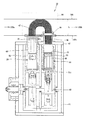
図1は、本実施形態のスターリングエンジンを示す正面図である。図3は、同側面図である。図1及び図3に示すように、本実施形態のスターリングエンジン10は、α型(2ピストン形)のスターリングエンジンであり、二つのパワーピストン20、30を備えている。低温側パワーピストン30のピストン31は、高温側パワーピストン20のピストン21に対して、クランク角で90°程度遅れて動くように位相差がつけられている。
(First embodiment)
FIG. 1 is a front view showing a Stirling engine of the present embodiment. FIG. 3 is a side view of the same. As shown in FIGS. 1 and 3, the
高温側パワーピストン20のシリンダ(以下高温側シリンダという)22の上部の空間(膨張空間)には、加熱器47によって加熱された作動流体が流入する。低温側パワーピストン30のシリンダ(以下低温側シリンダという)32の上部の空間(圧縮空間)には、冷却器45によって冷却された作動流体が流入する。再生器46は、膨張空間と圧縮空間を作動流体が往復する際に熱を蓄える。即ち、膨張空間から圧縮空間へと作動流体が流れる時には、再生器46は、作動流体より熱を受け取り、圧縮空間から膨張空間へと作動流体が流れる時には、蓄えられた熱を作動流体に渡す。
The working fluid heated by the
2つのピストン21、31の往復動に伴い、作動ガスの往復流動が生じて高温側シリンダ22の膨張空間と低温側シリンダ32の圧縮空間にある作動流体の割合が変化するとともに、全内容積も変わるため、圧力の変動が生じる。2つのピストン21、31がそれぞれ同位置にある場合の圧力を比較すると、膨張ピストン21についてはその上昇時より下降時の方がかなり高く、圧縮ピストン31については逆に低くなる。このため、膨張ピストン21は外部に対し大きな正の仕事(膨張仕事)を行い、圧縮ピストン31は外部から仕事(圧縮仕事)を受ける必要がある。膨張仕事は、一部が圧縮仕事に使われ、残りが駆動軸40を介して出力として取り出される。
As the two
高温側シリンダ22及び低温側シリンダ32のそれぞれは、円筒状に形成されており、直方体の箱状に形成されたクランクケース41に直立した状態で配置される。高温側シリンダ22及び低温側シリンダ32は、クランクケース41の上面部42に固定されている。低温側シリンダ32は、その全体がクランクケース41の内部に収容されている。高温側シリンダ22は、その一部がクランクケース41の内部に収容され、残りの一部はクランクケース41の外部にまで延びるように設けられている。
Each of the high
低温側シリンダ32の上方には、冷却器45が設けられ、その冷却器45の上には再生器46が設けられ、その再生器46の上には、加熱器47の一端部が接続されている。加熱器47の他端部は、高温側シリンダ22の上部に接続されている。冷却器45には、冷却水が使用される。
A cooler 45 is provided above the low
作動流体は、その平均圧力が高い程、冷却器45や加熱器47による同じ温度差に対しての圧力差が大きくなるので高い出力が得られる。そのため、高温側シリンダ22、低温側シリンダ32内の作動流体は高圧に保持されている。本実施形態では、クランクケース41の内部全体が高圧に保持されている。即ち、クランクケース41が高圧容器として機能している。
The higher the average pressure of the working fluid, the higher the pressure difference with respect to the same temperature difference caused by the cooler 45 and the
ピストン21,31は、円柱状に形成されている。ピストン21、31の外周面とシリンダ22、32の内周面との間には、それぞれ数十μmの微小クリアランスが設けられており、そのクリアランスには、スターリングエンジン10の作動流体(空気)が介在して
いる。後述するように、ピストン21,31は、それぞれシリンダ22、32に対して空気軸受48により非接触の状態で支持されている。したがって、ピストン21,31の周囲には、ピストンリングは設けられておらず、また、一般にピストンリングと共に使用される潤滑油も使用されていない。但し、シリンダ22、32の内周面には、固定潤滑材が付されている。空気軸受48の作動流体の摺動抵抗は元々極めて低いが、更に低減するために、固定潤滑材が付されている。上記のように、空気軸受48は、作動流体(気体)により膨張空間、圧縮空間それぞれの気密を保ち、リングレスかつオイルレスでクリアランスシールを行う。
The
本実施形態のスターリングエンジン10は、車両においてガソリンエンジン(内燃機関)と共に用いられてハイブリッドシステムを構成する。即ち、スターリングエンジン10は、ガソリンエンジンの排気ガスを熱源として用いる。図2に示すように、スターリングエンジン10の加熱器47が車両のガソリンエンジンの排気管100の内部に配置され、排気ガスから回収した熱エネルギーにより作動流体が加熱されてスターリングエンジン10が作動する。なお、スターリングエンジン10の加熱器47の取付位置は、車両の内燃機関の排気系であれば、排気管100に限定されない。
The
本実施形態のスターリングエンジン10は、排気管100の内部にその加熱器47が収容されるというように車両内の限られたスペースに設置されるため、装置全体がコンパクトである方が設置の自由度が増す。そのために、スターリングエンジン10では、2つのシリンダ22、32をV字形ではなく、直列並行に配置した構成を採用している。
The
加熱器47が排気管100の内部に配置されるに際しては、排気管100の内部において相対的に高温の排気ガスが流れる上流側(ガソリンエンジンに近い側)100aに、加熱器47の高温側シリンダ22側が位置し、相対的に低温の排気ガスが流れる下流側(ガソリンエンジンから遠い側)100bに加熱器47の低温側シリンダ32側が位置するように配置される。
When the
スターリングエンジン10の熱源は、上記のように車両のガソリンエンジンの排気ガスであり、スターリングエンジン10に専用に用意された熱源ではない。そのため、それほど高い熱量が得られるわけではなく、排気ガスの例えば約800℃程度の熱量でスターリングエンジン10が作動する必要がある。そのために、本実施形態では、スターリングエンジン10の内部フリクションを可能な限り低減させることとしている。
The heat source of the
本実施形態では、スターリングエンジンの内部フリクションのうち最も摩擦損失が大きいピストンリングによる摩擦損失を無くすため、上記の通り、ピストンリングを使用せずに、その代わりに、シリンダ22、32とピストン21、31との間には、それぞれ空気軸受(エアベアリング)48が設けられる。
In the present embodiment, in order to eliminate the friction loss due to the piston ring having the largest friction loss among the internal friction of the Stirling engine, as described above, instead of using the piston ring, instead of the
空気軸受48は、摺動抵抗が極めて小さいため、スターリングエンジン10の内部フリクションを大幅に低減させることができる。上記のように、空気軸受48を用いても、シリンダ22、32とピストン21、31との間の気密は確保されるため、膨張空間、圧縮空間の高圧の作動流体が膨張、収縮の際に漏れるという問題は生じない。
Since the
空気軸受48は、シリンダ22、32とピストン21、31の間の微小なクリアランスで発生する空気の圧力(分布)を利用して,ピストン21、31が空中に浮いた形となる軸受である。本実施形態の空気軸受48では、シリンダ22、32とピストン21、31との間の直径クリアランスは数十μmである。
The
空中に物体を浮上させる空気軸受を実現するには、機構的に空気圧が強くなる部分(圧
力勾配)ができるようにする他に、後述するように高圧の空気を吹きつけるものでもよい。本実施形態では、高圧の空気を吹き付けるタイプの空気軸受ではなく、医療用ガラス製注射器のシリンダとピストンの間で用いられている空気軸受と同じ構成の空気軸受が用いられる。
In order to realize an air bearing that floats an object in the air, in addition to forming a portion (pressure gradient) where the air pressure is mechanically increased, high-pressure air may be blown as described later. In the present embodiment, an air bearing having the same configuration as that of an air bearing used between a cylinder and a piston of a medical glass syringe is used instead of an air bearing that blows high-pressure air.
また、空気軸受48を使用することで、ピストンリングで用いる潤滑油が不要となるので、潤滑油によりスターリングエンジン10の熱交換器(再生器46、加熱器47など)90が劣化するという問題が発生しない。なお、本実施形態では、上記のように、ピストンリングにおける摺動抵抗と潤滑油の問題が解消されれば足りるので、流体軸受のうち油を使用する油軸受を除いた、気体軸受であれば空気軸受48に限られることなく適用することができる。
Further, since the use of the
本実施形態のピストン21、31とシリンダ22、32との間には、静圧空気軸受を用いることも可能である。静圧空気軸受とは、加圧流体を噴出させ、発生した静圧によって物体(本実施形態ではピストン21、31)を浮上させるものである。また、静圧空気軸受に代えて、動圧空気軸受を用いることも可能である。
It is also possible to use a static pressure air bearing between the
空気軸受48を用いて、ピストン21、31をシリンダ22、32内で往復運動させる際には、直線運動精度を空気軸受48の直径クリアランス未満にしなくてはならない。また、空気軸受48の負荷能力が小さいため、ピストン21、31のサイドフォースを実質的にゼロにしなくてはならない。即ち、空気軸受48は、シリンダ22、32の直径方向(横方向,スラスト方向)の力に耐える能力(耐圧能力)が低いため、シリンダ22、32の軸線に対するピストン21、31の直線運動精度が高い必要がある。
When the
特に、本実施形態で採用する、微小クリアランスの空気圧を用いて浮上させて支持するタイプの空気軸受48は、高圧の空気を吹き付けるタイプに比べても、スラスト方向の力に対する耐圧能力が低いため、その分だけ高いピストンの直線運動精度が要求される。
In particular, the
上記の理由から、本実施形態では、図3に示すように、ピストン・クランク部にグラスホッパの機構(近似直線リンク)50を採用する。グラスホッパの機構50は、他の直線近似機構(例えばワットの機構)に比べて、同じ直線運動精度を得るために必要な機構のサイズが小さくて済むため、装置全体がコンパクトになるという効果が得られる。特に、本実施形態のスターリングエンジン10は、自動車のガソリンエンジンの排気管100の内部にその加熱器47が収容されるというように限られたスペースに設置されるため、装置全体がコンパクトである方が設置の自由度が増す。
For this reason, in the present embodiment, as shown in FIG. 3, a grasshopper mechanism (approximate linear link) 50 is employed in the piston / crank portion. The
また、グラスホッパの機構50は、同じ直線運動精度を得るために必要な機構の重量が他の機構よりも軽量で済むため、燃費の点で有利である。さらに、グラスホッパの機構50は、機構の構成が比較的簡単であるため、構成(製造・組み立て)し易い。
Further, the
次に、図3〜図11を参照して、グラスホッパの近似直線機構50について説明する。
Next, the approximate
A.ピストン・クランク機構の概要:
図4−1は、従来のスターリングエンジンにおけるピストン・クランク機構を示す説明図であり、図4−2は、本実施形態のスターリングエンジン10におけるピストン・クランク機構を示す説明図である。図4−1に示すように、従来の機構は、シリンダ110と、ピストン120と、コネクティングロッド130と、クランクシャフト140とを備えている。ピストン120と、コネクティングロッド130は、ピストン120の中央部付近においてピストンピン160で互いに連結されている。コネクティングロッド130とクランクシャフト140は、クランクピン162で連結されている。ピストン120が上
下に往復運動すると、クランクシャフト140がその軸142(「駆動軸」とも呼ぶ)を中心に回転する。
A. Outline of piston / crank mechanism:
FIG. 4A is an explanatory view showing a piston / crank mechanism in a conventional Stirling engine, and FIG. 4B is an explanatory view showing a piston / crank mechanism in the
図4−2は、スターリングエンジン10のピストン・クランク機構の概略構成を示している。本実施形態において、ピストン・クランク機構は、高温側パワーピストン20側と低温側パワーピストン30側とで共通の構成を採用しているため、以下では、低温側パワーピストン30側についてのみ説明し、高温側パワーピストン20側についての説明は省略する。
FIG. 4B shows a schematic configuration of the piston / crank mechanism of the
スターリングエンジン10のピストン・クランク機構は、シリンダ32と、ピストン31と、コネクティングロッド65と、クランクシャフト61とを備えており、さらに近似直線機構50も備えている。近似直線機構50は、上述した通り、グラスホッパの近似直線機構である。
The piston / crank mechanism of the
図3及び図4−2に示すように、ピストン31には、ピストン支柱部64が接続されている。ピストン31とピストン支柱部64とが別体として形成されていている。このピストン31の下端部とピストン支柱部64の上端部は、ピン67によって互いに回動可能に連結されている。ピストン支柱部64は、ピストン支柱部64の下端においてピストンピン60で互いに連結されている。コネクティングロッド65とクランクシャフト61は、クランクピン62で連結されている。ピストン31が上下に往復運動すると、クランクシャフト61がその軸40(「駆動軸」とも呼ぶ)を中心に回転する。
As shown in FIGS. 3 and 4-2, a
近似直線機構50は、2つの横方向リンク52,54と、1つの縦方向リンク56とを有している。第1の横方向リンク52の一端は、ピストンピン60の位置においてピストン支柱部64の下端に回動可能に連結されている。第2の横方向リンク54の一端は、第1の横方向リンク52の中間の所定の位置において第1の横方向リンク52に回動可能に連結されている。第2の横方向リンク54の他端は、ピストン・クランク機構の所定の位置に回動可能に固定されている。縦方向リンク56の一端は、第1の横方向リンク52のピストンピン60とは反対側の端部において、第1の横方向リンク52と回動可能に連結されている。縦方向リンク56の他端は、ピストン・クランク機構の所定の位置に回動可能に固定されている。
The approximate
図4−1及び図4−2において、黒丸で表されている連結部(駆動軸40など)は、その軸を中心に回転または回動するが、シリンダ32との相対位置が変化しない連結点(以下「支点」と呼ぶ)である。また、白丸で表されている連結部(ピストンピン60など)は、その軸を中心に回転または回動するとともに、シリンダ32との相対位置が変化する連結点(以下「移動連結点」と呼ぶ)である。ここで、「回転」とは360度以上の範囲で回ることを意味しており、「回動」とは、360度未満の範囲で回ることを意味している。
In FIGS. 4A and 4B, a connecting portion (such as the drive shaft 40) represented by a black circle rotates or rotates about the axis, but does not change the relative position with the
なお、図4−1,図4−2では、本実施形態のスターリングエンジン10のうち、ピストン・クランク機構とシリンダ32以外は図示が省略されている。
4A and 4B, the illustration of the
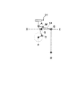
図5の(A)〜(C)は、本実施形態のピストン・クランク機構のリンク構成を示す説明図である。図5の(A)は、シリンダ32と、ピストン31と、コネクティングロッド65と、クランクシャフト61のみを示している。また、図5の(B)は、近似直線機構50のみを示している。図5の(C)は、図4−2に示した機構と同じものであり、図5の(A),(B)の構成を組合わせたものである。
(A)-(C) of FIG. 5 is explanatory drawing which shows the link structure of the piston crank mechanism of this embodiment. FIG. 5A shows only the
図5の(A)〜(C)においては、以下のように各種の連結点が表されている。
(1)移動連結点A:ピストンピン60(図4−2)の中心軸。
(2)移動連結点B:第1の横方向リンク52の移動連結点Aとは反対側の端部にある連結点。
(3)移動連結点C:コネクティングロッド65の移動連結点Aとは反対側の端部にある連結点。
(4)移動連結点M:第1の横方向リンク52の中間点にある連結点。
(5)支点P:クランクシャフト61の中心軸(駆動軸)。
(6)支点Q:第2の横方向リンク54の移動連結点Mと反対側の端部にある連結点。
(7)支点R:縦方向リンク56の移動連結点Bと反対側の端部にある連結点。
In (A) to (C) of FIG. 5, various connection points are represented as follows.
(1) Moving connection point A: central axis of the piston pin 60 (FIG. 4-2).
(2) Moving connection point B: A connection point at the end of the first
(3) Moving connecting point C: A connecting point at the end of the connecting
(4) Moving connection point M: A connection point at the midpoint of the first
(5) Support point P: the central axis (drive shaft) of the
(6) Support point Q: A connection point at the end of the second
(7) Support point R: A connection point at the end of the
移動連結点Aはピストンピン60の中心軸であり、ピストン31の往復運動に伴って上下方向Z(図5の(B))に沿って移動する。本明細書において、上下方向Zとは、シリンダ32の軸方向中心線(「軸中心」とも呼ぶ)に沿った方向を意味する。移動連結点A,Bは、第1の横方向リンク52の両端の連結点である。移動連結点Bは、縦方向リンク56が支点Rを中心に回動するのに伴って、円弧状の軌跡上を移動する。また、この移動連結点Bは、第2の横方向リンク54の支点Qの上下方向位置Xとほぼ同じ上下方向位置をとるように設定されている。
The moving connection point A is the central axis of the
なお、仮想的に縦方向リンク56の長さを無限大に設定し、移動連結点Bが、支点Qと同一の上下方向位置X上を直線的に移動するようにすれば、移動連結点Aは上下方向Zに沿って完全な直線に近い運動を行う。現実には、縦方向リンク56の長さは有限なので、移動連結点Aは直線運動からわずかにずれた軌跡上を移動する(これについては後述する)。ほぼ完全な直線運動機構は、縦方向リンク56の代わりに、移動連結点Bを直線的に案内するガイド部を採用すれば実現可能であるが、このガイド部と移動連結点Bとの摩擦が増大する。従って、摩擦の低減の観点からは、本実施形態の近似直線機構50の方が完全な直線運動機構よりも好ましい。
If the length of the
第1の横方向リンク52の中間にある移動連結点Mの位置は、以下の関係を満足するように設定されている。
AM×QM=BM2
The position of the moving connection point M in the middle of the first
AM × QM = BM 2
ここで、AMは連結点A,M間の距離を意味し、QMは連結点Q,M間の距離、BMは連結点B,M間の距離をそれぞれ意味している。 Here, AM means the distance between the connection points A and M, QM means the distance between the connection points Q and M, and BM means the distance between the connection points B and M, respectively.
図6−1〜図6−4は、ピストン31の移動に伴うピストン・クランク機構の形状変化を示している。近似直線機構50の3つの移動連結点A,B,Mのうちで、移動連結点A,Mはピストン31の移動に伴ってかなり大きく移動するが、縦方向リンク56の上端の移動連結点Bはあまり移動しないことが解る。図6−1には、近似直線機構50の形状変化の程度を示す指標として利用できる2つの角度θ、φが示されている。第1の角度θは、横方向Xから測った第2の横方向リンク54の角度∠MQXである。また、第2の角度φは、上下方向Zからの縦方向リンク56の傾き角で∠BRZである。これらの角度θ,φの値が取る範囲は、移動連結点Aの移動範囲(即ちピストン31のストローク)の設定と、近似直線機構50の各リンクの長さに依存する。
6A to 6D show changes in the shape of the piston / crank mechanism accompanying the movement of the
上記のように、ピストン31の下端部とピストン支柱部64の上端部は、ピン67によって互いに回動可能に連結されている。この構成では、ピストン支柱部64の下端の軌跡が直線から多少ずれた場合にも、そのズレが、ピストン31を傾かせる力として働かない(即ち、ピストン支柱部64の下端のズレがピストン31にほとんど影響を与えない)という利点がある。即ち、グラスホッパの機構50の往復運動時に生じる直線運動からのズレを吸収するために、ピストン31とピストン支柱部64とをリジッドにではなく、相対
的に移動可能な状態(フリーな状態)で連結する。本実施形態では、一例としてピン67を用いて連結している。また、ピストンとピストン支柱部とが一体に形成されている場合に比べて、ピストンを近似直線機構及びコネクティングロッドと組み付ける作業が容易になるという利点もある。一方、図示はしないが、ピストン支柱部64とピストン31とを一体として構成した場合には、仮に何らかの原因でピストン31がシリンダ32に対して傾きかけた場合にも、ピストン支柱部64が近似直線運動を行うときに、その傾きが矯正されるという利点がある。
As described above, the lower end portion of the
図7−1は、本実施形態におけるピストン・クランク機構の具体的な寸法の一例を示す説明図である。図7−2は、移動連結点Aの軌跡を示す説明図である。図7−1に示されている寸法は、上述した関係(AM×QM=BM2)を満足していることが解る。図7−2に示されているように、移動連結点Aの軌跡は、近似的な直線部分を含んでおり、この近似的な直線部分がピストン31のストロークの範囲として利用される。このとき、ピストン31のストロークの範囲は、上死点における直線からのズレ量が、下死点における直線からのズレ量よりも小さくなるように設定される。ここで、「直線からのズレ量」の「直線」とは、シリンダ32の軸方向中心線を意味している。図7−2の例では、上死点におけるズレ量は約5μmであり、下死点におけるズレ量は約20μmである。なお、この数値は常温で測定したものである。
7-1 is explanatory drawing which shows an example of the specific dimension of the piston crank mechanism in this embodiment. FIG. 7B is an explanatory diagram of the locus of the moving connection point A. It can be seen that the dimensions shown in FIG. 7-1 satisfy the relationship (AM × QM = BM 2 ) described above. As shown in FIG. 7B, the trajectory of the moving connection point A includes an approximate straight line portion, and this approximate straight line portion is used as the stroke range of the
上死点における移動連結点Aの直線からのズレ量が、下死点におけるズレ量よりも小さくなるように設定する理由は、上死点近傍では圧縮空気による力がピストン31にかかるからである(同様に、高温側パワーピストン20では、上死点近傍では膨張空気による力がピストン21にかかるからである)。即ち、上死点におけるズレ量が小さければ、圧縮空気による力によってピストン31に(又は膨張空気による力によってピストン21に)かかるスラスト(横方向の力)が小さくなるので、ピストン31とシリンダ32(又はピストン21とシリンダ22)との摩擦を低減することができる。一方、下死点では圧縮空気による力(又は膨張空気による力)が掛からないので、多少のズレがあっても上死点に比べて摩擦への影響は小さい。
The reason why the amount of deviation from the straight line of the moving connection point A at the top dead center is set to be smaller than the amount of deviation at the bottom dead center is that the force by the compressed air is applied to the
なお、移動連結点Aの軌跡における近似的直線部分は、各リンク52、54,56の長さを大きくすることによって大きくすることが可能であるが、リンクを長くすると近似直線機構50のサイズが大きくなるという問題がある。換言すれば、上死点や下死点における直線からのズレ量と、近似直線機構50のサイズとは、トレードオフの関係にある。これらの点を考慮すると、ピストン31の上死点における移動連結点Aの直線からのズレ量は、常温で測定して約10μm以下になるように近似直線機構50を構成することが好ましい。また、下死点におけるズレ量は、約20μm以下になるようにすることが好ましい。
The approximate straight line portion in the locus of the moving connection point A can be increased by increasing the length of each
図7−2に示すように、ピストン31のストロークの範囲を設定した場合には、第2の横方向リンク54の角度θは、8.8°〜−17.9°の範囲の値をとる(図7−1)。角度θの最大値(8.8°)は、ピストン31が上死点にある場合(図6−1)に相当し、最小値(−17.9°)はピストン31が下死点にある場合(図6−3)に相当する。縦方向リンク56の角度φは、0°〜2.2°の範囲の値をとる。角度φの最小値(0°)は、連結点Q、A、M、Bがほぼ一直線上に並ぶ場合に相当し、最大値(2.2°)は、角度θの絶対値が最も大きくなる場合(この例では下死点)に相当する。なお、これらの角度θ、φの値の範囲は、近似直線機構50の各リンクの寸法と、ピストン31のストローク範囲の設定に依存する。
As shown in FIG. 7-2, when the range of the stroke of the
B.具体的形状例:
図8および図9は、本実施形態におけるピストン・クランク機構の具体的な形状の一例
を示している。上記の通り、ピストン31は、円柱状に形成されている。ピストン31の外周面には、ピストンリング用の溝及びピストンリングは設けられていない。ピストン31の平面視(横断面)形状は、高精度な真円状に形成されている。シリンダ32は円筒状に形成されており、シリンダ32の内周部の平面視形状は、高精度な真円状に形成されている。ピストン31の外周面とシリンダ32の内周部との間には、上記の通り、空気軸受48が設けられている。ピストン31及びシリンダ32の内周部のそれぞれの平面視形状が高精度な真円状に形成されていることにより、シール性の良い空気軸受48が実現される。
B. Specific shape examples:
8 and 9 show an example of a specific shape of the piston / crank mechanism in the present embodiment. As described above, the
ピストンピン60とピストン31との間には、ピストンピン60とピストン31との間を所定の距離以上確保するために、ピストン支柱部64が設けられている。ピストン支柱部64によって、ピストンピン60とピストン31との間に所定距離以上開くことによって、ピストン31が往復移動する際に、ピストン31と近似直線機構50が接触しないようにすることができる。
A
ピストン支柱部64の長さは、ピストン31の上端からピストンピン60までの長さが、ピストン31のストロークの約1/2倍以上で1倍未満の範囲の値になるように設定されていることが好ましい。その理由は、ピストン支柱部64の長さが過度に短いと、上死点において近似直線機構50がシリンダ32又はピストン31に衝突する可能性があるためである。また、ピストン支柱部64の長さが過度に長いとその重量が増加する分だけエネルギ損失が増すためである。
The length of the
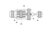
図9に示すように、ピストン支柱部64と、コネクティングロッド65と、第1、第2の横方向リンク52、54とは、ピストン31が上下動したときにも互いに干渉しないように構成されている。具体的には、図9の例では、ピストン支柱部64は、シリンダ32の軸方向中心に設けられており、ピストン支柱部64の両側が、コネクティングロッド65の2枚の板状部材で挟まれている。コネクティングロッド65の外側には、第1の横方向リンク52の2枚の板状部材が配置されている。これら3種類の部材24,30,52は、ピストンピン60で連結されている。また、第1の横方向リンク52の更に外側には、第2の横方向リンク54の2枚の板状部材が設置されている。即ち、この例では、コネクティングロッド65と2つの横方向リンク52、54とは、端部が2つの板状部材に分かれた二股構造をそれぞれ有しており、中央のピストン支柱部64を両側から挟むような位置にそれぞれ配置されている。
As shown in FIG. 9, the
図10は、図8からクランクが回転し、横方向リンク52、54が水平になった位置における要部縦断面図であり、図11は、図10のC−C断面図である。なお、図11では、図示の便宜上、コネクティングロッド65とピストン支柱部64とにそれぞれハッチングを付している。
10 is a longitudinal sectional view of a main part at a position where the crank is rotated from FIG. 8 and the
図12ないし図16は、ピストン支柱部64とコネクティングロッド65と第1の横方向リンク52が取り得る種々の形状および位置関係(連結状態)を示している。図12の配置は、図11の配置からコネクティングロッド65とピストン支柱部64の位置関係を逆にしたものである。即ち、図12では、中央にコネクティングロッド65が配置されており、その外側にピストン支柱部64の二股構造部分が配置され、さらにその外側に第1の横方向リンク52の二股構造部分が配置されている。また、第2の横方向リンク54の二股構造部分は、最も外側に配置されている。
FIGS. 12 to 16 show various shapes and positional relationships (connected states) that can be taken by the
図13の配置は、図11の配置からコネクティングロッド65と第1の横方向リンク52の位置関係を逆にしたものである。即ち、図13では、中央にピストン支柱部64が配置されており、その外側に第1の横方向リンク52の二股構造部分が配置され、さらにそ
の外側にコネクティングロッド65の二股構造部分が配置されている。
The arrangement of FIG. 13 is obtained by reversing the positional relationship between the connecting
図14の配置は、図12の配置からピストン支柱部64と第1の横方向リンク52の位置関係を逆にしたものである。即ち、図14では、中央にコネクティングロッド65が配置されており、その外側に第1の横方向リンク52の二股構造部分が配置され、さらにその外側にピストン支柱部64の二股構造部分が配置されている。
The arrangement of FIG. 14 is obtained by reversing the positional relationship between the
図15の配置は、図13の配置からピストン支柱部64と第1の横方向リンク52の位置関係を逆にしたものである。即ち、図15では、中央に第1の横方向リンク52が配置されており、その外側にピストン支柱部64の二股構造部分が配置され、さらにその外側にコネクティングロッド65の二股構造部分が配置されている。
The arrangement of FIG. 15 is obtained by reversing the positional relationship between the
図16の配置は、図15の配置からピストン支柱部64とコネクティングロッド65の位置関係を逆にしたものである。即ち、図16では、中央に第1の横方向リンク52が配置されており、その外側にコネクティングロッド65の二股構造部分が配置され、さらにその外側にピストン支柱部64の二股構造部分が配置されている。
The arrangement in FIG. 16 is obtained by reversing the positional relationship between the
図11〜図16のいずれの構成においても、第2の横方向リンク54の端部は二股構造になっており、他の部材64,65,52,60の外側に配置されている。そして、近似直線機構が動作する際には、第2の横方向リンク54の二股構造の間を、第1の横方向リンク52の端部が二股構造の間を通り抜けるように構成されている。このような構成によれば、コネクティングロッド65を短くしても、第1の横方向リンク52の端部と第2の横方向リンク54の端部とが干渉することが無いので、ピストン・クランク機構の縦方向の寸法の増大を抑制することができる。
11 to 16, the end of the second
また、図11〜図16に示す構成では、第1の横方向リンクの端部と、ピストン支柱部64の下端(ピストンの下端)と、コネクティングロッド65の上端とが、1つのピストンピン60で連結されている。このような構成によれば、第1の横方向リンク52とピストン支柱部64とコネクティングロッド65とが1つのピストンピン60で連結されるので、この連結部分の構造が単純になり、コンパクトにできるという利点がある。
In the configuration shown in FIGS. 11 to 16, the end of the first lateral link, the lower end of the piston support 64 (the lower end of the piston), and the upper end of the connecting
さらに、図11〜図16に示す構成では、第1の横方向リンク52の端部と、ピストン支柱部64の下端と、コネクティングロッド65の上端と、の3つの端部のうち2つの端部がそれぞれ二股構造を有しており、残りの1つの端部が前記2つの端部の二股構造の中心に配置されている。このような構成によれば、第1の横方向リンク52とピストン支柱部64とコネクティングロッド65との連結部分が対称な形になるので、非対称な形状とすることによるサイドフォースが発生することを防止できるという利点がある。
Furthermore, in the configuration shown in FIGS. 11 to 16, two of the three end portions, that is, the end portion of the first
なお、これらの部材64、65、52、54の位置関係は、図11ないし図16に示したもの以外の他の位置関係をとることも可能である。
The positional relationship between these
図17−1〜図17−3は、ピストン・クランク機構の変形例を示す説明図である、図17−1の機構は、図5の(A)〜(C)に示した本実施形態の機構の縦方向リンク56を連結点Bの上側に配置したものであり、他の構成は上記実施形態と同じである。図17−1の機構によっても、上記実施形態と同一の効果が得られる。
FIGS. 17-1 to 17-3 are explanatory views showing modifications of the piston / crank mechanism. The mechanism of FIG. 17-1 is the same as that of the present embodiment shown in FIGS. The
図17−2の機構は、図5の(A)〜(C)に示した本実施形態の機構の支点Qを移動連結点B側に移動して、移動連結点A(ピストンピン)と支点P(クランク軸)とを結ぶ直線上に配置したものであり、他の構成は上記実施形態と同じである。図17−3の機構は、支点Qをさらに右側に配置したものである。図17−2、図17−3の機構では、第
2の横方向リンク54の長さが上記実施形態よりも短くなっており、上記実施形態の機構よりもコンパクトであるという利点がある。図17−2の機構は、図17−1、図17−3の機構に比べて直線性が良いという利点がある。
The mechanism of FIG. 17-2 moves the fulcrum Q of the mechanism of the present embodiment shown in FIGS. 5A to 5C to the movement coupling point B side, and moves to the movement coupling point A (piston pin) and the fulcrum. It is arranged on a straight line connecting P (crankshaft), and the other configurations are the same as in the above embodiment. The mechanism shown in FIG. 17C has the fulcrum Q further disposed on the right side. In the mechanism of FIGS. 17-2 and 17-3, the length of the second
以上のように、上述した実施形態や変形例では、ピストン・クランク機構に近似直線機構50を設けることによって、ピストン31の下端がシリンダ32の軸中心に沿った近似的な直線状軌跡を移動するようにしたので、ピストン31の直線運動精度が高く、ピストン31のサイドフォースを実質的にゼロにすることが可能となり、ピストン31とシリンダ32との間にスラスト方向の耐圧能力の低い空気軸受48を設けても、問題が生じない。
As described above, in the above-described embodiments and modifications, the piston / crank mechanism is provided with the approximate
グラスホッパの近似直線機構は、近似直線上を移動する点(移動連結点A)が機構の一方の端部近傍に偏っているので、スターリングエンジン10のピストンの運動を規制するのに特に適しており、また、コンパクトな機構で良好な直線性を得ることが可能である。
The approximate linear mechanism of the grasshopper is particularly suitable for restricting the movement of the piston of the
10 スターリングエンジン
20 高温側パワーピストン
21 膨張ピストン
22 高温側シリンダ
30 低温側パワーピストン
31 圧縮ピストン
32 低温側シリンダ
45 冷却器
46 再生器
47 加熱器
48 空気軸受
50 近似直線機構
60 ピストンピン
62 クランクピン
64 ピストン支柱部
65 コネクティングロッド
67 ピン
90 熱交換器
100 排気管
DESCRIPTION OF
Claims (4)
シリンダと、
前記シリンダとの間に気体軸受を介して気密を保ちつつ前記シリンダ内を往復運動するピストンと、
前記ピストンに直接的又は間接的に連結され、前記ピストンが前記シリンダ内を往復運動するときに近似直線運動するように設けられた近似直線機構と
を備え、
前記気体軸受は、圧力分布で非接触に前記ピストンを支持する
ことを特徴とするスターリングエンジン。 A Stirling engine that uses an exhaust system of an internal combustion engine as a heat source,
A cylinder,
A piston that reciprocates in the cylinder while maintaining airtightness between the cylinder and a gas bearing;
An approximate linear mechanism connected to the piston directly or indirectly, and provided to perform an approximate linear motion when the piston reciprocates in the cylinder, and
The Stirling engine , wherein the gas bearing supports the piston in a non-contact manner with a pressure distribution .
更に、
駆動軸を中心に回転するクランクシャフトと、
前記ピストンから下方に延びるように設けられた延長部と、
前記延長部と前記クランクシャフトとを連結するコネクティングロッドと
を備え、
前記近似直線機構は、前記延長部と前記コネクティングロッドとの連結部に連結され、前記連結部が前記シリンダの軸方向中心線に沿って近似直線運動するように前記連結部の動きを規制する
ことを特徴とするスターリングエンジン。 The Stirling engine according to claim 1,
Furthermore,
A crankshaft that rotates around a drive shaft;
An extension provided to extend downward from the piston;
A connecting rod connecting the extension and the crankshaft;
The approximate linear mechanism is connected to a connecting portion between the extension portion and the connecting rod, and restricts the movement of the connecting portion so that the connecting portion performs an approximate linear motion along the axial center line of the cylinder. Stirling engine characterized by
前記ピストンと前記延長部は、相対的に回動可能に連結されている
ことを特徴とするスターリングエンジン。 The Stirling engine according to claim 2,
The Stirling engine, wherein the piston and the extension portion are connected so as to be relatively rotatable.
車両の前記内燃機関とを備えたハイブリッドシステムであって、
前記スターリングエンジンは、前記車両に搭載され、
前記スターリングエンジンの加熱器が前記内燃機関の排気系から受熱するように設けられた
ことを特徴とするハイブリッドシステム。 A Stirling engine according to any one of claims 1 to 3,
A hybrid system comprising the internal combustion engine of a vehicle,
The Stirling engine is mounted on the vehicle,
The hybrid system, wherein a heater of the Stirling engine is provided to receive heat from an exhaust system of the internal combustion engine.
Priority Applications (5)
| Application Number | Priority Date | Filing Date | Title |
|---|---|---|---|
| JP2003343416A JP3783706B2 (en) | 2003-10-01 | 2003-10-01 | Stirling engine and hybrid system including the same |
| PCT/JP2004/013953 WO2005033592A2 (en) | 2003-10-01 | 2004-09-24 | Stirling engine and hybrid system with the same |
| US10/564,351 US7458215B2 (en) | 2003-10-01 | 2004-09-24 | Stirling engine and hybrid system with the same |
| CN 200480028488 CN100523469C (en) | 2003-10-01 | 2004-09-24 | Stirling engine and hybrid system with the same |
| EP04788112.3A EP1669584B1 (en) | 2003-10-01 | 2004-09-24 | Stirling engine and hybrid system with the same |
Applications Claiming Priority (1)
| Application Number | Priority Date | Filing Date | Title |
|---|---|---|---|
| JP2003343416A JP3783706B2 (en) | 2003-10-01 | 2003-10-01 | Stirling engine and hybrid system including the same |
Publications (2)
| Publication Number | Publication Date |
|---|---|
| JP2005106009A JP2005106009A (en) | 2005-04-21 |
| JP3783706B2 true JP3783706B2 (en) | 2006-06-07 |
Family
ID=34537396
Family Applications (1)
| Application Number | Title | Priority Date | Filing Date |
|---|---|---|---|
| JP2003343416A Expired - Fee Related JP3783706B2 (en) | 2003-10-01 | 2003-10-01 | Stirling engine and hybrid system including the same |
Country Status (2)
| Country | Link |
|---|---|
| JP (1) | JP3783706B2 (en) |
| CN (1) | CN100523469C (en) |
Families Citing this family (11)
| Publication number | Priority date | Publication date | Assignee | Title |
|---|---|---|---|---|
| JP4978198B2 (en) | 2007-01-09 | 2012-07-18 | トヨタ自動車株式会社 | Stirling engine |
| JP4803140B2 (en) * | 2007-08-27 | 2011-10-26 | トヨタ自動車株式会社 | Piston engine and Stirling engine |
| JP4858424B2 (en) | 2007-11-29 | 2012-01-18 | トヨタ自動車株式会社 | Piston engine and Stirling engine |
| JP4730430B2 (en) | 2008-12-10 | 2011-07-20 | トヨタ自動車株式会社 | Piston engine |
| WO2010067728A1 (en) | 2008-12-10 | 2010-06-17 | トヨタ自動車株式会社 | Gas lubrication structure for piston, and stirling engine |
| JP4609577B2 (en) | 2008-12-17 | 2011-01-12 | トヨタ自動車株式会社 | Piston engine |
| TWI512191B (en) * | 2013-09-11 | 2015-12-11 | Univ Nat Cheng Kung | Pulse tube stirling engine |
| JP6384020B2 (en) * | 2015-01-26 | 2018-09-05 | 日立オートモティブシステムズ株式会社 | Actuator of link mechanism for internal combustion engine |
| US12128869B2 (en) | 2017-10-27 | 2024-10-29 | Quantum Industrial Development Corporation | External combustion engine series hybrid electric drivetrain |
| CN110410211B (en) * | 2019-06-20 | 2021-11-02 | 江苏雨燕模业科技股份有限公司 | Engine system with adjustable stroke |
| JP2023139592A (en) * | 2022-03-22 | 2023-10-04 | 本田技研工業株式会社 | Internal combustion engine with connection mechanism and connection mechanism |
Family Cites Families (2)
| Publication number | Priority date | Publication date | Assignee | Title |
|---|---|---|---|---|
| JPH0893547A (en) | 1994-09-20 | 1996-04-09 | Naoji Isshiki | Side thrust receiving device |
| JP3686353B2 (en) * | 2001-05-22 | 2005-08-24 | シャープ株式会社 | Stirling engine |
-
2003
- 2003-10-01 JP JP2003343416A patent/JP3783706B2/en not_active Expired - Fee Related
-
2004
- 2004-09-24 CN CN 200480028488 patent/CN100523469C/en not_active Expired - Fee Related
Also Published As
| Publication number | Publication date |
|---|---|
| CN1860290A (en) | 2006-11-08 |
| CN100523469C (en) | 2009-08-05 |
| JP2005106009A (en) | 2005-04-21 |
Similar Documents
| Publication | Publication Date | Title |
|---|---|---|
| JP3783705B2 (en) | Stirling engine and hybrid system using the same | |
| JP5945574B2 (en) | Rod seal assembly for Stirling engine | |
| JP3783706B2 (en) | Stirling engine and hybrid system including the same | |
| JP4285338B2 (en) | Stirling engine | |
| US7458215B2 (en) | Stirling engine and hybrid system with the same | |
| EP2184479B1 (en) | Piston engine and stirling engine | |
| JP4289224B2 (en) | Stirling engine | |
| WO2006070832A1 (en) | Piston device, stirling engine, and external combustion engine | |
| JP4306467B2 (en) | Stirling engine and hybrid system | |
| JP4737303B2 (en) | Stirling engine | |
| US20070000249A1 (en) | Exhaust heat recovery apparatus | |
| US20060283417A1 (en) | Piston and piston apparatus | |
| JP5391799B2 (en) | Stirling engine heat exchanger and Stirling engine | |
| JP4059249B2 (en) | Piston engine | |
| JP7202365B2 (en) | Hot gas engine with stepped piston | |
| JP2009293406A (en) | Piston engine and stirling engine | |
| JP4239900B2 (en) | Stirling engine | |
| JP2005337179A (en) | Stirling engine | |
| JP4682899B2 (en) | Piston engine | |
| JP4301082B2 (en) | Piston device | |
| JP2006188956A (en) | Piston engine | |
| JP2011007138A (en) | Cooler of sterling engine and sterling engine | |
| US20130061826A1 (en) | Stirling engine gas lubrication structure | |
| JP2005180358A (en) | Heat exchanger, Stirling engine and hybrid system |
Legal Events
| Date | Code | Title | Description |
|---|---|---|---|
| RD02 | Notification of acceptance of power of attorney |
Free format text: JAPANESE INTERMEDIATE CODE: A7422 Effective date: 20050524 |
|
| A131 | Notification of reasons for refusal |
Free format text: JAPANESE INTERMEDIATE CODE: A131 Effective date: 20051018 |
|
| A521 | Written amendment |
Free format text: JAPANESE INTERMEDIATE CODE: A523 Effective date: 20051214 |
|
| TRDD | Decision of grant or rejection written | ||
| A01 | Written decision to grant a patent or to grant a registration (utility model) |
Free format text: JAPANESE INTERMEDIATE CODE: A01 Effective date: 20060221 |
|
| A61 | First payment of annual fees (during grant procedure) |
Free format text: JAPANESE INTERMEDIATE CODE: A61 Effective date: 20060306 |
|
| R150 | Certificate of patent or registration of utility model |
Free format text: JAPANESE INTERMEDIATE CODE: R150 |
|
| FPAY | Renewal fee payment (event date is renewal date of database) |
Free format text: PAYMENT UNTIL: 20100324 Year of fee payment: 4 |
|
| FPAY | Renewal fee payment (event date is renewal date of database) |
Free format text: PAYMENT UNTIL: 20110324 Year of fee payment: 5 |
|
| FPAY | Renewal fee payment (event date is renewal date of database) |
Free format text: PAYMENT UNTIL: 20110324 Year of fee payment: 5 |
|
| FPAY | Renewal fee payment (event date is renewal date of database) |
Free format text: PAYMENT UNTIL: 20120324 Year of fee payment: 6 |
|
| FPAY | Renewal fee payment (event date is renewal date of database) |
Free format text: PAYMENT UNTIL: 20120324 Year of fee payment: 6 |
|
| FPAY | Renewal fee payment (event date is renewal date of database) |
Free format text: PAYMENT UNTIL: 20130324 Year of fee payment: 7 |
|
| FPAY | Renewal fee payment (event date is renewal date of database) |
Free format text: PAYMENT UNTIL: 20130324 Year of fee payment: 7 |
|
| FPAY | Renewal fee payment (event date is renewal date of database) |
Free format text: PAYMENT UNTIL: 20140324 Year of fee payment: 8 |
|
| LAPS | Cancellation because of no payment of annual fees |