JP3824518B2 - Optical disk device - Google Patents
Optical disk device Download PDFInfo
- Publication number
- JP3824518B2 JP3824518B2 JP2001344726A JP2001344726A JP3824518B2 JP 3824518 B2 JP3824518 B2 JP 3824518B2 JP 2001344726 A JP2001344726 A JP 2001344726A JP 2001344726 A JP2001344726 A JP 2001344726A JP 3824518 B2 JP3824518 B2 JP 3824518B2
- Authority
- JP
- Japan
- Prior art keywords
- data
- optical disk
- reading
- optical
- written
- Prior art date
- Legal status (The legal status is an assumption and is not a legal conclusion. Google has not performed a legal analysis and makes no representation as to the accuracy of the status listed.)
- Expired - Lifetime
Links
- 230000003287 optical effect Effects 0.000 title claims description 133
- 238000004092 self-diagnosis Methods 0.000 claims description 22
- 230000005856 abnormality Effects 0.000 claims description 10
- 230000007257 malfunction Effects 0.000 claims description 8
- 238000003745 diagnosis Methods 0.000 claims description 6
- 230000007547 defect Effects 0.000 description 5
- 238000007689 inspection Methods 0.000 description 4
- 230000007246 mechanism Effects 0.000 description 4
- 238000000034 method Methods 0.000 description 4
- 230000008569 process Effects 0.000 description 4
- 230000008439 repair process Effects 0.000 description 4
- 230000002950 deficient Effects 0.000 description 3
- 230000004397 blinking Effects 0.000 description 2
- 238000010586 diagram Methods 0.000 description 2
- 238000004904 shortening Methods 0.000 description 2
- 230000000694 effects Effects 0.000 description 1
- 238000005259 measurement Methods 0.000 description 1
- 238000012986 modification Methods 0.000 description 1
- 230000004048 modification Effects 0.000 description 1
- 238000003825 pressing Methods 0.000 description 1
Images

Classifications
-
- G—PHYSICS
- G11—INFORMATION STORAGE
- G11B—INFORMATION STORAGE BASED ON RELATIVE MOVEMENT BETWEEN RECORD CARRIER AND TRANSDUCER
- G11B19/00—Driving, starting, stopping record carriers not specifically of filamentary or web form, or of supports therefor; Control thereof; Control of operating function ; Driving both disc and head
- G11B19/02—Control of operating function, e.g. switching from recording to reproducing
- G11B19/04—Arrangements for preventing, inhibiting, or warning against double recording on the same blank or against other recording or reproducing malfunctions
Landscapes
- Optical Recording Or Reproduction (AREA)
Description
【0001】
【発明の属する技術分野】
本発明は、CD、CD―ROM、CD−RやCD−RW等の光ディスクからデータを読み出し可能および/または光ディスクへデータ書込み可能な光ディスク装置に関する。
【0002】
【従来の技術】
光ディスクからのデータの読み出しや、光ディスクへデータを書込み可能な光ディスク装置を、ユーザーが使用しているとき、データの読み出しやデータの書込みが出来なくなることがある。
このようにデータの読み出しやデータの書込みが出来なくなる場合には、光ディスク装置が実際に故障している場合もあるが、ユーザーの操作ミス、コンピュータ側の故障またはホストコンピュータ側との接続不良などの理由によるものであって、実際には光ディスク装置自体は故障していない場合もある。
【0003】
【発明が解決しようとする課題】
ユーザーの操作ミス、ホストコンピュータ側の故障、ホストコンピュータ側との接続不良などの原因により、光ディスク装置のデータの読み出しやデータの書込みが出来なくなった場合であっても、ユーザー側ではその原因がわからないため、光ディスク装置が故障しているとして、販売店やメーカーの消費者窓口等へ光ディスク装置を持参して相談し、相談の結果、販売店や消費者窓口等を介して光ディスク装置のメーカーへ送り返してくることとなる。
しかし、元々故障ではない光ディスク装置を販売店や消費者窓口へ持参して相談する行為は無駄な行為であり、ユーザ自身で装置自体の故障か否かを簡単に判断できるようになればこのような無駄な行為を行なわなくとも済むという課題があった。
【0004】
一方、元々故障ではない光ディスク装置を送り返してきているので、メーカー側においては、本来しなくともよいことである無駄な検査に時間を費やさねばならないという課題がある。
【0005】
そこで、本発明は上記課題を解決すべくなされ、その目的とするところは、データの読み出しおよび/またはデータの書込み時の動作が不良であっても、光ディスク装置自体の故障であるか否かをユーザ側で容易に判断可能な光ディスク装置を提供することにある。
【0006】
【課題を解決するための手段】
すなわち、本発明にかかる光ディスク装置によれば、光ディスクに記録されたデータを読み出し可能および/または光ディスクへデータ書込み可能な光ディスク装置において、背面に設けられたジャンパスイッチが自己診断モードに設定され、且つ自己診断開始スイッチがオンされることによって、データ読み出しの異常および/またはデータ書込みの異常の有無を、ホストコンピュータ等の他の機器とは独立して単独で診断する制御手段を具備することを特徴としている。
この構成を採用することによって、ユーザ側で光ディスク装置単体で装置自体の故障の有無を判断することができる。このため、ユーザからすれば販売店や消費者窓口等へ光ディスク装置を持参したり、メーカーへ光ディスク装置を送り返したりするなどの手間をかけないようにすることができる。またメーカー側においても無駄な検査等を実施しなくとも済む。
【0007】
また、前記制御手段は、装着されている光ディスクに診断用データの書込みを行ない、該データ書込み時の動作の不良の有無を診断することを特徴とするので、データ書込み時の不良の有無を光ディスク装置単体で診断可能である。
【0008】
さらに、前記制御手段は、予めデータが書込まれている光ディスクから連続してデータを読み出し、該データ読み出し時の動作の不良の有無を診断することを特徴とするので、データ読み出し時の不良の有無を光ディスク装置単体で診断可能である。
【0009】
なお、前記制御手段は、予めデータが書き込まれている光ディスクからランダムにデータを読み出し、光ディスク上の任意の読み出し位置へのアクセス動作の不良の有無を診断することにより、光ピックアップが光ディスク上の様々な位置へ正確にジャンプできるか否かを光ディスク装置単体で診断可能である。
【0010】
また、前記制御手段は、装着されている光ディスクに診断用データの書込みを行ない、該データ書込み時の動作の不良の有無を診断し、該診断用データが書込まれた光ディスクから連続して診断用データを読み出し、該診断用データ読み出し時の動作の不良の有無を診断し、該診断用データが書込まれた光ディスクからランダムに診断用データを読み出し、光ディスク上の任意の読み出し位置へのアクセス動作の不良の有無を診断することを特徴とする。
この構成によれば、ブランクの光ディスクを装着することにより、光ディスク装置単体でデータ書込み時の不良の有無、データ読み出し時の不良の有無および光ピックアップが光ディスク上の様々な位置へ正確にジャンプできるか否かを診断する事が可能となる。
【0011】
前記制御手段は、乱数発生手段と、該乱数発生手段で発生させた乱数によって、光ディスク上でデータを読み出すアドレスを決定するアドレス決定手段とを具備し、該アドレス決定手段で決定した光ディスク上のアドレスへ、データを読みとる光ピックアップを移動させるように制御することもできる。
【0012】
なお、前記断制御手段による診断の結果、データの読み出しおよび/または書込みの際の動作に異常が検出された場合には、検出された異常内容を記憶する記憶手段を具備することを特徴とする。
このような構成を採用すると、ユーザが自己診断をした結果、実際に光ディスク装置が故障していることが判明してメーカーに返送されたときにメーカー側では記憶手段に記憶された内容を読み出すことによって、故障個所を即座に認識する事が可能となり、修理個所の検査時間および修理時間の短縮化等に寄与する。
【0013】
【発明の実施の形態】
以下、本発明の好適な実施の形態を添付図面に基づいて詳細に説明する。
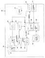
まず、図1に光ディスク装置の内部構造についてのブロック図を示し、これに基づいて本実施形態の構成を、それらの動作と共に説明する。
光ディスク装置30は、光ディスク10に照射するレーザ光を発振するレーザダイオード(図示せず)および光ディスク10からの反射光を受けるフォトディテクタ(図示せず)を有する光ピックアップ19を具備している。
【0014】
光ピックアップ19は、光ディスク10のトラッキング方向へ光ピックアップ19を移動させる送り機構20によって移動可能に設けられている。送り機構20は、光ピックアップ19がスライド可能に支持されているスレッド軸(図示せず)や送りモータ(図示せず)等から構成される。
光ディスク10は、スピンドルモータ22の回転軸に設けられたターンテーブル上に載置され、スピンドルモータ22の駆動によって回転する。
【0015】
スピンドルモータ22の光ディスク10の回転、光ピックアップ19内の対物レンズ(図示せず)のトラッキング、光ピックアップ19内の対物レンズのフォーカスおよび光ピックアップ19の送り機構20の制御はサーボプロセッサ24が行なう。
サーボプロセッサ24は、光ディスク10から反射してきた反射光の強度信号からRFアンプ26によって抽出された誤差信号に基づいて、対物レンズのトラッキングやフォーカス等の各サーボ制御を行なう。
また、サーボプロセッサ24は、CPU28からのアドレス信号に基づき、指示されたアドレスに光ピックアップ19が移動するように送り機構20を制御する。
なお、CPU28は、RFアンプ26で抽出されたデータをデコードするデコーダ29からの信号に基づいてサーボプロセッサに制御信号を出力している。
【0016】
光ディスク10へのデータの書込みは、レーザドライバー32が光ピックアップ19内のレーザダイオードを制御して行なわれる。
【0017】
以下、本実施形態特有の構成について説明する。
CPU28には、ユーザが所定の操作をすることにより、ホストコンピュータや試験装置等の他の機器と接続されていなくとも単独で、データ書込みの異常の有無および/またはデータ読み出しの異常の有無を検出可能な自己診断を行なうことができる自己診断プログラムが予め記憶されたROM等の記憶手段35が接続されている。
CPU28は、ユーザが所定の操作をした場合には、記憶手段35から自己診断プログラムを読み出し、この自己診断プログラムに基づいて各構成要素を制御して自己診断モードを作動させる。
【0018】
上記ユーザの所定の動作とは、具体的には、ホストコンピュータ(図示せず)等と接続されているケーブルの取り外しやジャンパスイッチの設定(後述する)を行なった後、自己診断開始スイッチをオンすることである。
自己診断開始スイッチ41は、光ディスク装置30のいずれかの個所に設けられている。
【0019】
CPU28内には、乱数発生手段36とアドレス決定手段38とが設けられている。CPU28は、乱数発生手段36で発生した乱数によって、任意のアドレスを決定し、この任意のアドレスをサーボプロセッサ24へ伝達する。
サーボプロセッサ24は、CPU28で決定された任意のアドレスに光ピックアップ19を移動させることができる。
【0020】
CPU28には、光ディスク10へデータを書込んだ際にエラーが生じた場合、または光ディスク10からデータを読み出した場合または光ディスク10の任意のアドレスへ光ピックアップ19が正確に移動できなかった場合には、そのエラー内容に該当するエラーコードを記憶するRAM等から構成される記憶手段34が接続されている。
【0021】
また、光ディスク装置30のフロントパネルには、光ディスク装置の作動状態を知らせるためのインジケータ40が設けられている。インジケータ40が設けられていることによって、ユーザは光ディスク装置が現在どのような動作を行なっているかを確認することができる。
インジケータの具体例としては、緑色とオレンジ色のどちらか一方の色および緑色とオレンジ色とを混色させた黄色を発光可能なLEDから構成されている。
【0022】
また、CPU28は、インジケータを制御するインジケータ制御信号をインジケータ40へ出力し、インジケータの表示を制御することができる。
インジケータ40の表示の制御は、CPU28が現在行なっている動作に基づいて行なわれる。
【0023】
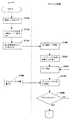
本発明の動作について、図2〜図3のフローチャートに基づいて説明する。
ユーザが光ディスク装置が故障しているのではないかと考えた場合には、ユーザは、まずホストコンピュータ等の外部機器と接続されている接続ケーブル(図示せず)を取り外す(ステップS100)。このように接続ケーブルを取り外した状態で診断するので、他の機器が故障していて光ディスク装置30自体が故障していない場合であっても光ディスク装置30を故障と診断してしまうようなことを防止し、他の機器に関係なく独立して光ディスク装置30自身の故障の有無を診断できる。
【0024】
次にステップS102へ移行し、ユーザはジャンパスイッチ(図示せず)の設定を行なう。ジャンパスイッチは光ディスク装置30の背面に設けられており、初期設定時に操作する以外は使用しないスイッチである。ジャンパスイッチを所定の位置に設定することにより、自己診断モードが動作可能となる。
続いてステップS104において、ユーザが自己診断開始スイッチ41をオンにすることで、光ディスク装置30の自己診断モードが開始する。具体的な自己診断開始スイッチ41は、イジェクトボタンと電源スイッチ(図示せず)であって、両者を同時に押すことで自己診断モードが開始される。
【0025】
ユーザに自己診断スイッチ41(ここでは、イジェクトボタンと電源スイッチ)をオンにされることで、CPU28は記憶手段35から自己診断プログラムを読み出し、自己診断モードを開始する(ステップS200)。
まず、ステップS202において、CPU28はインジケータ制御信号を出力し、インジケータ40を緑色とオレンジ色とを100msecごとに交互点灯させる。これにより、ユーザは自己診断が開始されたことを認識できる。
【0026】
次のステップS204において、ステップCPU28は、トレイを排出するようにトレイ駆動手段(図示せず)を制御する。
トレイが突出すると、ユーザがトレイにブランクディスクを載置する(ステップS106)。すると、光ディスク装置30は、載置された光ディスクがブランクディスクであるか否かを検出する(ステップS206)。次のステップS208で光ディスクがブランクディスクで有ることが判明した場合は、ステップS110へ移行し、ブランクディスクではないことが判明した場合には、ステップS204へ戻ってトレイを排出する。
【0027】
ブランクディスクがトレイに載置されていることが判明した場合には、CPU28は、ステップS210において最高速で光ディスク全面にデータ記録を行なうように制御する。
このとき、記録するデータはCPU28においてランダムに選択した特に意味のないでたらめのデータである。このデータは、乱数発生手段36が発生させるようにしてもよい。
このようにして、光ディスク10全面にデータを書込むことにより、データ書込み時のエラーを検出できる。
【0028】
次のステップS212では、先のステップS210で書込んだデータを、最高速で連続して読み出すように、CPU28が制御する。
なお、ここでは先に書込んだデータが正常に書込まれたか否かを判断するわけではなく、書込んだデータのサブコードのみをチェックするようにしている。
このようにして、光ディスク10から連続してデータの読み出す際のエラーが検出可能である。
【0029】
次のステップS214では、CPU28は、光ピックアップ19を任意の位置にジャンプさせ、そのジャンプさせた位置においてデータを所定の時間だけ読み出し、すぐに別の任意のアドレスへジャンプさせることを所定回数繰り返し実施させる。
ジャンプ先のアドレスは、乱数発生手段36が発生させた乱数によって決定される。また、本実施形態では、ジャンプ先のデータを1秒間読み出し、これを100回繰り返し行なうようにしている。
このようにして、光ディスク上のあらゆる位置にジャンプできるかどうかが確認できる。
【0030】
そして次のステップS216では、ステップS210,S212,S214において実施した全面書込み、連続読み出し、ランダム読み出しのいずれかにエラーが生じている場合にはステップS218へ、いずれにもエラーが無かった場合にはステップS217へ移行する。
【0031】
ステップS218においては、エラーが生じたことをユーザに知らせるように、CPU28がインジケータ40をエラーがあった旨の表示をさせる。
具体的インジケータ40の表示は、データ書込み時または読み出し時にエラーが発生した場合には緑色の1回点滅、光ディスクのイニシャル時にエラーが発生した場合には緑色の2回点滅によって行なわれる。
【0032】
次のステップS220においては、CPU28は、エラーの内容に該当するエラーコードを記憶手段34に記憶させ、自己診断モードが終了する。
エラーが見つかって自己診断モードが終了した場合には、トレイは排出されずにそのまま終了する。
【0033】
一方、ステップS217では、インジケータ40はエラーがなかったことをユーザに知らせるために、消灯する。
そして次のステップS219においては、CPU28が、トレイを排出するようにトレイ駆動手段を制御し、終了する。
【0034】
なお、エラーの例としては、イジェクト・ローディングのエラー、PMA・TOC・ATIP等の読込みエラー、線速度測定エラー、レーザー不発光等様々なエラーがある。
【0035】
また上述してきた実施形態においては、データの書込みはCPU28で発生させた適当なデータを書込み、連続データ読み出しの際にはデータのベリファイまでは行なっていなかった。しかし、書込むデータを予め設定しておくなどして、連続データ読み出しの際にデータのベリファイを行なってデータが正確に書込まれたか否かを診断するようにしても好適である。
【0036】
以上本発明につき好適な実施例を挙げて種々説明したが、本発明はこの実施例に限定されるものではなく、発明の精神を逸脱しない範囲内で多くの改変を施し得るのはもちろんである。
【0037】
【発明の効果】
本発明に係る光ディスク記録再生装置によれば、ユーザー側で光ディスク装置単体で装置自体の故障の有無を判断することができるので、ユーザからすれば販売店や消費者窓口等へ光ディスク装置を持参したり、メーカーへ光ディスク装置を送り返したりするなどの手間をかけないようにすることができる。
【0038】
また、制御手段は、装着されている光ディスクに診断用データの書込みを行ない、該データ書込み時の動作の不良の有無を診断することによって、データ書込み時の不良の有無を光ディスク装置単体で診断可能である。
さらに、制御手段は、予めデータが書込まれている光ディスクから連続してデータを読み出し、該データ読み出し時の動作の不良の有無を診断することによって、データ読み出し時の不良の有無を光ディスク装置単体で診断可能である。
【0039】
なお、制御手段は、予めデータが書き込まれている光ディスクからランダムにデータを読み出し、光ディスク上の任意の読み出し位置へのアクセス動作の不良の有無を診断することにより、光ピックアップが光ディスク上の様々な位置へ正確にジャンプできるか否かを光ディスク装置単体で診断可能である。
【0040】
また、制御手段は、装着されている光ディスクに診断用データの書込みを行ない、データ書込み時の動作の不良の有無を診断し、診断用データが書込まれた光ディスクから連続して診断用データを読み出し、診断用データ読み出し時の動作の不良の有無を診断し、該診断用データが書込まれた光ディスクからランダムに診断用データを読み出し、光ディスク上の任意の読み出し位置へのアクセス動作の不良の有無を診断するので、ブランクの光ディスクを装着することにより、光ディスク装置単体でデータ書込み時の不良の有無、データ読み出し時の不良の有無および光ピックアップが光ディスク上の様々な位置へ正確にジャンプできるか否かを診断する事が可能となる。
【0041】
なお、制御手段は、乱数発生手段と、該乱数発生手段で発生させた乱数によって、光ディスク上でデータを読み出すアドレスを決定するアドレス決定手段とを具備し、アドレス決定手段で決定した光ディスク上のアドレスへ、データを読みとる光ピックアップを移動させるように制御するので、予め移動させるアドレスを設定しておかなくともよい。
【0042】
なお、制御手段による診断の結果、データの読み出しおよび/または書込みの際の動作に異常が検出された場合には、検出された異常内容を記憶する記憶手段を具備するので、ユーザが自己診断をした結果、実際に光ディスク装置が故障していることが判明してメーカーに返送されたときにメーカー側では記憶手段に記憶された内容を読み出すことによって、故障個所を即座に認識する事が可能となり、修理個所の検査時間や修理時間の短縮化等に寄与する。
【図面の簡単な説明】
【図1】本発明に係る光ディスク装置を説明するブロック図である。
【図2】光ディスク装置の自己診断動作を説明するフローチャートである。
【図3】図2に示したフローチャートの続きである。
【符号の説明】
10 光ディスク
19 光ピックアップ
20 移動手段
22 スピンドルモータ
24 サーボプロセッサ
26 RFアンプ
28 CPU(制御手段)
29 デコーダ
30 光ディスク装置
32 レーザドライバー
34,35 記憶手段
36 乱数発生手段
38 アドレス決定手段
40 インジケータ
41 自己診断開始スイッチ[0001]
BACKGROUND OF THE INVENTION
The present invention relates to an optical disc apparatus capable of reading data from and / or writing data to an optical disc such as a CD, a CD-ROM, a CD-R, and a CD-RW.
[0002]
[Prior art]
When a user is using an optical disk device that can read data from an optical disk or write data to an optical disk, the data may not be read or written.
In this way, when it becomes impossible to read or write data, the optical disk device may actually be out of order, but a user's operation error, computer failure or poor connection with the host computer, etc. For reasons, the optical disk apparatus itself may not actually be out of order.
[0003]
[Problems to be solved by the invention]
Even if data cannot be read from or written to the optical disk device due to a user operation error, host computer failure, or poor connection with the host computer, the user does not know the cause. Therefore, if the optical disc device is out of order, bring the optical disc device to a retailer or a consumer contact of the manufacturer, etc., and send it back to the manufacturer of the optical disc device via the retailer or the consumer contact. Will come.
However, the act of bringing an optical disk device that is not originally out of order to a dealer or a consumer service and consulting is a useless act, and if the user can easily determine whether or not the device itself is malfunctioning, it is like this There was a problem that it was not necessary to perform unnecessary actions.
[0004]
On the other hand, since the optical disk device which is not originally out of order has been sent back, there is a problem that the manufacturer has to spend time for a useless inspection which is not necessary.
[0005]
Therefore, the present invention has been made to solve the above-mentioned problems, and the object of the present invention is to determine whether or not the optical disk apparatus itself is faulty even if the data reading and / or data writing operation is defective. An object of the present invention is to provide an optical disc apparatus that can be easily determined by a user.
[0006]
[Means for Solving the Problems]
That is, according to the optical disc apparatus of the present invention, in the optical disc apparatus capable of reading data recorded on the optical disc and / or writing data to the optical disc, the jumper switch provided on the back is set to the self-diagnosis mode, and by self-diagnosis starting switch is turned on, characterized by comprising control means for diagnosing the presence or absence of abnormality of the abnormality and / or data writing of the data read, independently of the other devices such as a host computer alone It is said.
By adopting this configuration, it is possible for the user to determine whether or not there is a failure in the optical disk device alone. For this reason, it is possible for the user to avoid troubles such as bringing the optical disk device to a store or a consumer service, or sending the optical disk device back to the manufacturer. Moreover, it is not necessary for the manufacturer to carry out unnecessary inspections.
[0007]
In addition, since the control means writes diagnostic data on the optical disc loaded, and diagnoses whether there is a malfunction in the data writing, the presence / absence of the malfunction in the data writing is recorded on the optical disc. Diagnosis is possible with a single device.
[0008]
Further, the control means continuously reads data from an optical disk on which data has been written in advance, and diagnoses whether there is a malfunction in reading the data. The presence / absence of the optical disk device can be diagnosed.
[0009]
The control means randomly reads data from an optical disk on which data has been written in advance, and diagnoses whether there is a failure in the access operation to an arbitrary read position on the optical disk, so that the optical pickup can perform various operations on the optical disk. It is possible to diagnose whether or not it is possible to accurately jump to a correct position with a single optical disk device.
[0010]
In addition, the control means writes diagnostic data to an optical disc loaded, diagnoses whether there is a malfunction in the data writing, and continuously diagnoses from the optical disc on which the diagnostic data is written. Read out the diagnostic data, diagnose the presence / absence of an operation failure when reading out the diagnostic data, randomly read out the diagnostic data from the optical disk in which the diagnostic data is written, and access any reading position on the optical disk It is characterized by diagnosing the presence or absence of defective operation.
According to this configuration, by mounting a blank optical disk, whether or not there is a defect when writing data, whether there is a defect when reading data, and whether the optical pickup can accurately jump to various positions on the optical disk It becomes possible to diagnose whether or not.
[0011]
The control means includes a random number generation means and an address determination means for determining an address from which data is read on the optical disk by a random number generated by the random number generation means, and an address on the optical disk determined by the address determination means The optical pickup that reads data can be controlled to move.
[0012]
In addition, when an abnormality is detected in the operation at the time of data reading and / or writing as a result of the diagnosis by the disconnection control means, a storage means for storing the detected abnormality content is provided. .
When such a configuration is adopted, when the user performs self-diagnosis and the optical disk apparatus is actually found to be out of order and returned to the manufacturer, the manufacturer reads out the contents stored in the storage means. As a result, it becomes possible to immediately recognize the failure location, which contributes to shortening the inspection time and repair time of the repair location.
[0013]
DETAILED DESCRIPTION OF THE INVENTION
DESCRIPTION OF EXEMPLARY EMBODIMENTS Hereinafter, preferred embodiments of the invention will be described in detail with reference to the accompanying drawings.
First, FIG. 1 shows a block diagram of the internal structure of the optical disc apparatus, and based on this, the configuration of the present embodiment will be described together with the operation thereof.
The
[0014]
The
The
[0015]
The
The
The
The
[0016]
Data writing to the
[0017]
Hereinafter, a configuration unique to the present embodiment will be described.
The
When the user performs a predetermined operation, the
[0018]
Specifically, the user's predetermined operation is to turn on the self-diagnosis start switch after removing a cable connected to a host computer (not shown) or setting a jumper switch (described later). It is to be.
The self-diagnosis start switch 41 is provided in any part of the
[0019]
In the
The
[0020]
When an error occurs when data is written to the
[0021]
In addition, an
As a specific example of the indicator, it is composed of an LED capable of emitting yellow which is a mixed color of either green or orange and green and orange.
[0022]
Moreover, CPU28 can output the indicator control signal which controls an indicator to the
The display of the
[0023]
The operation of the present invention will be described with reference to the flowcharts of FIGS.
When the user thinks that the optical disk device is out of order, the user first removes a connection cable (not shown) connected to an external device such as a host computer (step S100). Since the diagnosis is performed with the connection cable removed as described above, the
[0024]
In step S102, the user sets a jumper switch (not shown). The jumper switch is provided on the back surface of the
Subsequently, in step S104, when the user turns on the self-diagnosis start switch 41, the self-diagnosis mode of the
[0025]
When the user turns on the self-diagnosis switch 41 (here, the eject button and the power switch), the
First, in step S202, the
[0026]
In the next step S204, the
When the tray protrudes, the user places a blank disc on the tray (step S106). Then, the
[0027]
If it is found that the blank disc is placed on the tray, the
At this time, the data to be recorded is random data that is selected at random in the
By writing data on the entire surface of the
[0028]
In the next step S212, the
Here, it is not determined whether the previously written data has been normally written, but only the subcode of the written data is checked.
In this way, an error in reading data continuously from the
[0029]
In the next step S214, the
The jump destination address is determined by the random number generated by the random number generation means 36. In this embodiment, the jump destination data is read out for 1 second, and this is repeated 100 times.
In this way, it can be confirmed whether or not it is possible to jump to any position on the optical disc.
[0030]
In the next step S216, if an error has occurred in any of the full-surface writing, continuous reading, and random reading performed in steps S210, S212, and S214, the process proceeds to step S218, and if there is no error in any of them. Control goes to step S217.
[0031]
In step S218, the
The
[0032]
In the next step S220, the
If an error is found and the self-diagnosis mode is terminated, the tray is terminated without being ejected.
[0033]
On the other hand, in step S217, the
In the next step S219, the
[0034]
Examples of errors include various errors such as ejection / loading errors, reading errors such as PMA / TOC / ATIP, linear velocity measurement errors, and laser non-light emission.
[0035]
In the above-described embodiments, data is written by writing appropriate data generated by the
[0036]
While the present invention has been described in detail with reference to a preferred embodiment, the present invention is not limited to this embodiment, and it goes without saying that many modifications can be made without departing from the spirit of the invention. .
[0037]
【The invention's effect】
According to the optical disk recording / reproducing apparatus of the present invention, the user can determine whether or not the optical disk apparatus itself has a failure, so that the user can bring the optical disk apparatus to a store or a consumer service. Or sending the optical disk device back to the manufacturer.
[0038]
In addition, the control means writes diagnostic data to the mounted optical disk and diagnoses the presence or absence of data writing failure by diagnosing whether or not the data writing operation is defective. It is.
Further, the control means continuously reads out data from the optical disk on which data has been written in advance, and diagnoses the presence or absence of an operation failure at the time of data reading, thereby determining whether or not there is a failure at the time of data reading. Diagnosis is possible.
[0039]
The control means randomly reads data from an optical disk on which data has been written in advance, and diagnoses whether there is a defect in the access operation to an arbitrary read position on the optical disk, so that the optical pickup can perform various operations on the optical disk. Whether or not it is possible to accurately jump to the position can be diagnosed by the optical disk device alone.
[0040]
In addition, the control means writes diagnostic data to the mounted optical disk, diagnoses whether there is a malfunction in data writing, and continuously outputs diagnostic data from the optical disk on which the diagnostic data is written. Reads and diagnoses whether or not there is a malfunction in reading the diagnostic data, reads diagnostic data from the optical disk on which the diagnostic data is written, and accesses an arbitrary read position on the optical disk. Whether or not there is a defect when writing data, whether there is a defect when reading data, and whether the optical pickup can accurately jump to various positions on the optical disk by mounting a blank optical disk. It becomes possible to diagnose whether or not.
[0041]
The control means includes a random number generation means and an address determination means for determining an address from which data is read on the optical disk by the random number generated by the random number generation means. The address on the optical disk determined by the address determination means. Since the optical pickup for reading data is controlled to move, it is not necessary to set the address to be moved in advance.
[0042]
In addition, when an abnormality is detected in the operation at the time of data reading and / or writing as a result of the diagnosis by the control means, a storage means for storing the detected abnormality content is provided, so that the user can perform self-diagnosis. As a result, when the optical disk device is actually found to be out of order and returned to the manufacturer, the manufacturer can immediately recognize the failure location by reading the contents stored in the storage means. This contributes to shortening the inspection time and repair time at repair locations.
[Brief description of the drawings]
FIG. 1 is a block diagram illustrating an optical disc apparatus according to the present invention.
FIG. 2 is a flowchart illustrating a self-diagnosis operation of the optical disc apparatus.
FIG. 3 is a continuation of the flowchart shown in FIG.
[Explanation of symbols]
DESCRIPTION OF
29
Claims (7)
背面に設けられたジャンパスイッチが自己診断モードに設定され、且つ自己診断開始スイッチがオンされることによって、データ読み出しの異常および/またはデータ書込みの異常の有無を、ホストコンピュータ等の他の機器とは独立して単独で診断する制御手段を具備することを特徴とする光ディスク装置。In an optical disc apparatus capable of reading data recorded on an optical disc and / or writing data to the optical disc,
When the jumper switch provided on the back is set to the self-diagnosis mode and the self-diagnosis start switch is turned on , whether or not there is a data read error and / or data write error is detected with other devices such as a host computer. optical disk apparatus characterized by comprising control means for diagnosing independently by itself.
装着されている光ディスクに診断用データの書込みを行ない、該データ書込み時の動作の不良の有無を診断することを特徴とする請求項1記載の光ディスク装置。The control means includes
2. The optical disk apparatus according to claim 1, wherein diagnostic data is written to the optical disk mounted to diagnose the presence or absence of an operation failure during the data writing.
予めデータが書込まれている光ディスクから連続してデータの読み出しを行い、該データ読み出し時の動作の不良の有無を診断することを特徴とする請求項1または2記載の光ディスク装置。The control means includes
3. The optical disc apparatus according to claim 1, wherein data is continuously read from an optical disc in which data has been previously written, and the presence or absence of an operation failure at the time of reading the data is diagnosed.
予めデータが書き込まれている光ディスクからランダムにデータの読み出しを行い、光ディスク上の任意の読み出し位置へのアクセス動作の不良の有無を診断することを特徴とする請求項1,2または3記載の光ディスク装置。The control means includes
4. The optical disk according to claim 1, wherein data is randomly read from an optical disk in which data has been written in advance, and the presence or absence of an access operation to an arbitrary read position on the optical disk is diagnosed. apparatus.
装着されている光ディスクに診断用データの書込みを行ない、該データ書込み時の動作の不良の有無を診断し、
該診断用データが書込まれた光ディスクから連続して診断用データの読み出しを行い、該診断用データ読み出し時の動作の不良の有無を診断し、
該診断用データが書込まれた光ディスクからランダムに診断用データの読み出しを行い、光ディスク上の任意の読み出し位置へのアクセス動作の不良の有無を診断することを特徴とする請求項1記載の光ディスク装置。The control means includes
Write diagnostic data to the mounted optical disk, diagnose the presence or absence of malfunction during the data writing,
Continuously reading out diagnostic data from the optical disk in which the diagnostic data is written, diagnosing whether there is a malfunction in reading the diagnostic data,
2. The optical disk according to claim 1, wherein the diagnostic data is randomly read from the optical disk in which the diagnostic data is written, and the presence or absence of an access operation failure to an arbitrary reading position on the optical disk is diagnosed. apparatus.
乱数発生手段と、
該乱数発生手段で発生させた乱数によって、光ディスク上でデータを読み出すアドレスを決定するアドレス決定手段とを具備し、
該アドレス決定手段で決定した光ディスク上のアドレスへ、データを読みとる光ピックアップを移動させるように制御することを特徴とする請求項4または5記載の光ディスク装置。The control means includes
Random number generation means;
An address determining means for determining an address for reading data on the optical disk by a random number generated by the random number generating means;
6. The optical disk apparatus according to claim 4, wherein control is performed so that the optical pickup for reading data is moved to the address on the optical disk determined by the address determining means.
Priority Applications (3)
| Application Number | Priority Date | Filing Date | Title |
|---|---|---|---|
| JP2001344726A JP3824518B2 (en) | 2001-11-09 | 2001-11-09 | Optical disk device |
| DE10250652A DE10250652A1 (en) | 2001-11-09 | 2002-10-30 | Optical turntable |
| US10/286,912 US20030090965A1 (en) | 2001-11-09 | 2002-11-04 | Optical disk player |
Applications Claiming Priority (1)
| Application Number | Priority Date | Filing Date | Title |
|---|---|---|---|
| JP2001344726A JP3824518B2 (en) | 2001-11-09 | 2001-11-09 | Optical disk device |
Publications (2)
| Publication Number | Publication Date |
|---|---|
| JP2003151130A JP2003151130A (en) | 2003-05-23 |
| JP3824518B2 true JP3824518B2 (en) | 2006-09-20 |
Family
ID=19158202
Family Applications (1)
| Application Number | Title | Priority Date | Filing Date |
|---|---|---|---|
| JP2001344726A Expired - Lifetime JP3824518B2 (en) | 2001-11-09 | 2001-11-09 | Optical disk device |
Country Status (3)
| Country | Link |
|---|---|
| US (1) | US20030090965A1 (en) |
| JP (1) | JP3824518B2 (en) |
| DE (1) | DE10250652A1 (en) |
Families Citing this family (1)
| Publication number | Priority date | Publication date | Assignee | Title |
|---|---|---|---|---|
| US8291266B2 (en) * | 2009-09-15 | 2012-10-16 | International Business Machines Corporation | Server network diagnostic system |
Family Cites Families (2)
| Publication number | Priority date | Publication date | Assignee | Title |
|---|---|---|---|---|
| JPH0770173B2 (en) * | 1987-03-06 | 1995-07-31 | 松下電器産業株式会社 | Information recording / reproducing device |
| JPH096426A (en) * | 1995-06-20 | 1997-01-10 | Hitachi Ltd | Optical disk device, diagnostic method therefor, and diagnostic optical disk medium |
-
2001
- 2001-11-09 JP JP2001344726A patent/JP3824518B2/en not_active Expired - Lifetime
-
2002
- 2002-10-30 DE DE10250652A patent/DE10250652A1/en not_active Withdrawn
- 2002-11-04 US US10/286,912 patent/US20030090965A1/en not_active Abandoned
Also Published As
| Publication number | Publication date |
|---|---|
| JP2003151130A (en) | 2003-05-23 |
| DE10250652A1 (en) | 2003-05-28 |
| US20030090965A1 (en) | 2003-05-15 |
Similar Documents
| Publication | Publication Date | Title |
|---|---|---|
| US6834034B2 (en) | Optical disk data erasing apparatus and optical disk data erasing method | |
| JP3824518B2 (en) | Optical disk device | |
| EP1065664B1 (en) | Disk drive using plural optical heads, capable of identifying the types of media | |
| JPH096426A (en) | Optical disk device, diagnostic method therefor, and diagnostic optical disk medium | |
| JPH11134778A (en) | Optical disk device and information reading method of its device | |
| KR100444953B1 (en) | Pick-up test unit | |
| JP3968721B2 (en) | Optical disk device | |
| JP5057847B2 (en) | Equipment diagnostic equipment | |
| US8000190B2 (en) | Optical disk device and optical disk processing system | |
| JPH0476861A (en) | Information storage device | |
| JP2006040433A (en) | Recording medium reproducing apparatus and diagnostic method of recording medium reproducing apparatus | |
| US7242643B2 (en) | Optical disk apparatus | |
| JP2004178661A (en) | Optical disk device and optical disk medium for diagnosis | |
| JP2002117632A (en) | Playback unit and self-diagnostic recording medium used therefor | |
| JP2000243021A (en) | Method and device for determining medium compatibility for optical disk device | |
| JP3887822B2 (en) | Optical disk playback device | |
| JP4947004B2 (en) | Optical disc apparatus and optical disc processing system having the same | |
| JPH08161751A (en) | Optical disk drive | |
| JPH1153820A (en) | Disk unit with changer | |
| JP2001101696A (en) | Optical disk device and optical disk system | |
| JPH0831079A (en) | Data protection method and disk device | |
| JPH10134500A (en) | Optical disk drive system | |
| JP2001014774A (en) | Disk drive device | |
| JP2001067667A (en) | Optical disk drive adjusting device and optical disk drive device having self-diagnosis function | |
| JP2002190134A (en) | Optical head inspection device |
Legal Events
| Date | Code | Title | Description |
|---|---|---|---|
| A977 | Report on retrieval |
Free format text: JAPANESE INTERMEDIATE CODE: A971007 Effective date: 20050329 |
|
| A131 | Notification of reasons for refusal |
Free format text: JAPANESE INTERMEDIATE CODE: A131 Effective date: 20050426 |
|
| A521 | Written amendment |
Free format text: JAPANESE INTERMEDIATE CODE: A523 Effective date: 20050622 |
|
| TRDD | Decision of grant or rejection written | ||
| A01 | Written decision to grant a patent or to grant a registration (utility model) |
Free format text: JAPANESE INTERMEDIATE CODE: A01 Effective date: 20060613 |
|
| A61 | First payment of annual fees (during grant procedure) |
Free format text: JAPANESE INTERMEDIATE CODE: A61 Effective date: 20060627 |
|
| R150 | Certificate of patent or registration of utility model |
Free format text: JAPANESE INTERMEDIATE CODE: R150 |
|
| FPAY | Renewal fee payment (event date is renewal date of database) |
Free format text: PAYMENT UNTIL: 20090707 Year of fee payment: 3 |
|
| FPAY | Renewal fee payment (event date is renewal date of database) |
Free format text: PAYMENT UNTIL: 20100707 Year of fee payment: 4 |