JP3826257B2 - Exhaust gas purification device for compression ignition type internal combustion engine - Google Patents
Exhaust gas purification device for compression ignition type internal combustion engine Download PDFInfo
- Publication number
- JP3826257B2 JP3826257B2 JP31602799A JP31602799A JP3826257B2 JP 3826257 B2 JP3826257 B2 JP 3826257B2 JP 31602799 A JP31602799 A JP 31602799A JP 31602799 A JP31602799 A JP 31602799A JP 3826257 B2 JP3826257 B2 JP 3826257B2
- Authority
- JP
- Japan
- Prior art keywords
- fuel
- exhaust
- exhaust gas
- internal combustion
- combustion engine
- Prior art date
- Legal status (The legal status is an assumption and is not a legal conclusion. Google has not performed a legal analysis and makes no representation as to the accuracy of the status listed.)
- Expired - Lifetime
Links
Images
Classifications
-
- Y—GENERAL TAGGING OF NEW TECHNOLOGICAL DEVELOPMENTS; GENERAL TAGGING OF CROSS-SECTIONAL TECHNOLOGIES SPANNING OVER SEVERAL SECTIONS OF THE IPC; TECHNICAL SUBJECTS COVERED BY FORMER USPC CROSS-REFERENCE ART COLLECTIONS [XRACs] AND DIGESTS
- Y02—TECHNOLOGIES OR APPLICATIONS FOR MITIGATION OR ADAPTATION AGAINST CLIMATE CHANGE
- Y02T—CLIMATE CHANGE MITIGATION TECHNOLOGIES RELATED TO TRANSPORTATION
- Y02T10/00—Road transport of goods or passengers
- Y02T10/10—Internal combustion engine [ICE] based vehicles
- Y02T10/40—Engine management systems
Landscapes
- Exhaust Gas After Treatment (AREA)
- Electrical Control Of Air Or Fuel Supplied To Internal-Combustion Engine (AREA)
- Combined Controls Of Internal Combustion Engines (AREA)
Description
【0001】
【発明の属する技術分野】
本発明は、圧縮着火式内燃機関の排気浄化装置に関し、詳しくは、例えばディーゼルエンジンの排気中のNOxを主として除去する排気浄化装置に関する。
【0002】
【従来の技術】
内燃機関の排気管を流れる排気の空燃比がリーンのときに排気中のNOxを主として吸収し、前記空燃比がリッチ空燃比または理論空燃比のときにそれまで吸収していたNOxを放出する吸蔵還元型リーンNOx触媒を内燃機関の排気通路に配置して排気中のNOxを除去する技術が周知である(例えば特開平8−218920号公報参照)。
【0003】
吸蔵還元型リーンNOx触媒は、NOxを吸蔵し過ぎて飽和状態になると、吸収力が低下してしまい、そのままではその後の排気浄化ができない。
このため、排気浄化を継続するにはそれまで吸収していたNOxを放出して再び吸収できるようにする必要がある。しかし、NOxを放出するわけにはいかないので、還元剤を用いてNOxを窒素に還元してから放出する。
【0004】
吸蔵還元型リーンNOx触媒がNOxを吸蔵して飽和状態にあるかどうかは、例えば内燃機関の作動積算時間が所定量に達したかどうかを判断する。そして、作動積算時間が所定量に達した場合は、吸蔵還元型リーンNOx触媒がNOxで飽和状態にあると仮定する。
【0005】
そして、飽和状態にあると判定した後は、排気空燃比がリッチ空燃比または理論空燃比になるように機関運転を切り換えて吸蔵還元型リーンNOx触媒を還元雰囲気におき、その結果前記のように吸蔵還元型リーンNOx触媒からNOxを放出し、放出したNOxを排気中の未燃HCやCO等の還元成分で窒素に還元する。
【0006】
このようにNOxを吸蔵して飽和状態になっている吸蔵還元型リーンNOx触媒からNOxを放出して再びNOx吸蔵ができるようにすることを吸蔵還元型リーンNOx触媒の再生(以下「触媒再生」という。)を行うという。
【0007】
ところで、このような吸蔵還元型リーンNOx触媒をディーゼルエンジンに適用した場合、次のような問題が考えられる。
圧縮着火式内燃機関であるディーゼルエンジンは、その構造上および作動上の理由から空気過剰な状態で燃焼するので排気空燃比は大幅にリーンになる。したがって、ディーゼルエンジンにあっては、触媒再生を目的として、吸蔵還元型リーンNOx触媒に流入する排気をリッチ空燃比または理論空燃比にして前記還元成分を増大するには、例えば気筒への噴射燃料を大幅に増量して行う。
【0008】
しかし、ディーゼルエンジンは、圧縮行程において高温状態となっている圧縮空気に噴射した燃料とその周囲の空気との境界部分にできる可燃混合気層で燃焼を生じる。したがって、燃料噴射量を大幅に増量すると、燃焼室内に気化せずに液状のまま残る燃料が増大する。すると、この液状燃料は、前記可燃混合気層でその周囲の空気と接触しない状態のまま高温高圧を受けるので、当該液状燃料が恰も蒸し焼きにされたごときになってスモークとして排出される。
【0009】
スモークは触媒再生に寄与しないばかりか吸蔵還元型リーンNOx触媒に付着して吸蔵還元型リーンNOx触媒のNOx吸収力を低下させる。
このような理由から、これまで、吸蔵還元型リーンNOx触媒をディーゼルエンジンに適用した場合、排気空燃比をリッチ空燃比や理論空燃比にするのはスモークの発生を招来する虞があり、あまり好ましいものとは言い難かった。
【0010】
ところで、スモークは燃料の燃え残りであるから、スモークが発生しないようにするには、燃焼室での燃料の空気との混合割合を高めればよい。
このことを踏まえて実験および研究を重ねた結果、本願発明者は、空気と混合しやすい、換言すれば多くの酸素と結合しやすい燃料を触媒再生時に燃焼できれば、スモークの発生を抑制しながら、触媒再生用に排気空燃比をリッチ空燃比や理論空燃比にできるのではないかと考えた。
【0011】
【発明が解決しようとする課題】
本発明は上記実状に鑑みてなされたものであり、その解決しようとする課題は、排気管に吸蔵還元型リーンNOx触媒を適用した内燃機関において、排気の空燃比制御の実行によって排気空燃比を触媒再生用にリッチ空燃比や理論空燃比にしてもスモークの発生を抑制できる圧縮着火式内燃機関の排気浄化装置を提供することにある。
【0012】
【課題を解決するための手段】
本発明の圧縮着火式内燃機関の排気浄化装置は、上記実状に鑑みて発明されたものであって、次の手段を採用する。
(1)本発明の圧縮着火式内燃機関の排気浄化装置は、気筒内に機関作動用燃料を噴射する主噴射装置と、この主噴射装置によって噴射された前記燃料の燃焼によって排出される排気の浄化用に機関排気通路に備えられ、排気がリーン空燃比状態にあるときに排気中のNOxを吸蔵し、排気がリッチ空燃比または理論空燃比状態にあるときにそれまで吸蔵していたNOxを放出することで再生を図る吸蔵還元型リーンNOx触媒と、を有する圧縮着火式内燃機関の排気浄化装置において、前記吸蔵還元型リーンNOx触媒の再生要求時、前記機関作動用燃料をクラッキングすることで前記主噴射装置によって噴射される燃料よりも炭素数が低い低炭素数成分燃料を生成するとともにこの低炭素数成分燃料を前記気筒内で均一に分散する予混合噴霧を行う副噴射装置を有し、前記吸蔵還元型リーンNOx触媒の再生要求時に、前記副噴射装置から予混合噴霧された前記低炭素数成分燃料を、前記気筒において空気との混合割合が高い状態で燃焼させることを特徴とする。
【0013】
ここで「再生」とは、吸蔵還元型リーンNOx触媒に飽和状態で吸蔵されていたNOxを放出することにより吸蔵還元型リーンNOx触媒が再びNOxを吸蔵できるようになることをいう。
【0014】
「低炭素数成分燃料」とは、空気と混合し易く、換言すれば酸素と結合し易く、よって、低炭素数成分燃料を燃焼した場合にスモークの発生量を少なくできる燃料をいう。
【0015】
また、本発明に係る副噴射装置では、低炭素数成分燃料としてメタンの生成は行わない。メタンを燃焼しても化学変化しにくく、よってそのまま機関排気通路に排出され、その後、このメタンが排気浄化用触媒に至ってもそこでも反応しにくく、よって触媒による排気浄化ができないからである。
【0016】
「クラッキング」とは、周知のごとく有機化合物の分子を分解して、より小さな分子に変えることであり、クラッキングには、高温と高圧を利用する熱分解や触媒を利用する接触分解等が適用される。
【0017】
本発明では、吸蔵還元型リーンNOx触媒の再生要求時に、副噴射装置によって機関作動用燃料をクラッキングすることで低炭素数成分燃料を生成し、この低炭素数成分燃料を前記気筒内で均一に分散する予混合噴霧を行うため、主噴射装置によって機関作動用燃料が気筒内に噴射されると、機関作動用燃料と低炭素数成分燃料とが混在するようになる。
【0018】
しかも、低炭素数成分燃料は空気と混合し易いため、機関作動用燃料と低炭素数成分燃料とからなる気筒内の燃料は、機関作動用燃料だけを気筒内に噴射した場合と比べ、全体として空気との混合割合が高くなる(空気と結合し易くなる)。
【0019】
よって、機関作動用燃料と低炭素数成分燃料とが混在する燃料を燃焼するとスモークの発生量を効果的に減少させることができる。
したがって、このような機関作動用燃料と低炭素数成分燃料とが混在する燃料を燃焼した時に排出される排気の空燃比を空燃比制御を行ってリッチ空燃比や理論空燃比とし、そのような空燃比の排気を吸蔵還元型リーンNOx触媒の再生用に使えば、スモークは発生しにくくなる。
(2)前記低炭素数成分燃料の炭素数は11以下であることが好ましい。すなわち、機関作動用燃料が例えば軽油の場合、ガソリン並に炭素数の少ない低炭素数成分燃料を生成することが好ましい。
(3)前記副噴射装置によって噴霧される前記低炭素数成分燃料は、機関吸気通路に導入することが好ましい。
【0020】
炭素数が11以下の軽質な低炭素数成分燃料であれば、それ自体がもともと付着しにくい性質があるが、このようにすると、副噴射装置から噴射された低炭素数成分燃料のシリンダボア(シリンダ開口),吸気ポート,ピストン,シリンダ壁等への付着がなく、また、オイルが燃料によって希釈されてしまうオイル希釈を生じることもない。
(4)前記副噴射装置の作動時には、前記主噴射装置による燃料噴射は遅角または/および減量して行うとよい。
【0021】
これは次の理由による。
気筒の容積は変わらないので、低炭素数成分燃料が導入される分に応じて主噴射装置による燃料の導入量を低減させなければ出力が増大してしまう。したがって、低炭素数成分燃料の気筒内への導入の有無に拘わらず、出力を一定にさせる必要上このような制御をすることが望ましいのである。
(5)前記クラッキングには熱分解を適用し、この熱分解は無酸素状態で行うことが好ましい。
【0022】
無酸素状態で熱分解すると、燃料が酸化しない非酸化状態で熱分解のみ行えるからであり、この場合、燃料の水素重合を無くして煤の生成を抑制できるからである。
(6)前記熱分解は700℃以上で行うことが好ましい。
【0023】
700℃よりも低温状態で熱分解を行うと、炭素数11以下にクラッキングするのに長い時間必要であり、メタンの生成量も多くなるからである。
この点700℃以上の加熱物に接触させて瞬間的にクラッキングを行うとメタンの生成量は少なくなる。また、クラッキングが短時間で行われるため、クラッキングされた燃料の吸気系への調量の制御性も容易となる。
【0024】
【発明の実施の形態】
以下、本発明の実施の形態を添付した図面に基づいて説明する。
〈実施の形態〉
図1を用いて、第1の実施の形態を説明する。
【0025】
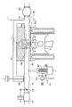
図1に内燃機関として例示するディーゼルエンジン1の全体構造を概略示す。
エンジン1のシリンダブロック2に形成されたシリンダ2aには、ピストン3が上下動可能に設けられている。ピストン3の上部には、凹部6を燃焼室として形成してある。
【0026】
シリンダブロック2は、その上部にシリンダヘッド7が載置固定され、その内部には、燃焼室6に臨む吸気ポート8と排気ポート9とが形成されている。
これら吸気ポート8および排気ポート9には、それぞれ吸気バルブ8aおよび排気バルブ9aが組み込まれ、また、吸気バルブ8aと排気バルブ9aとの間には、図示しないインジェクションポンプとつながっているインジェクタ11を燃焼室6に臨んだ状態で取り付けてある。
【0027】
そして、インジェクタ11からは、インジェクションポンプのポンプ圧を受けて、適切な時期に適正量の高圧燃料が燃焼室6に向けて噴射される。インジェクタ11は、燃焼室6に機関作動用燃料として軽油を噴射するのでこれを便宜上主噴射装置という。
【0028】
また、吸気ポート8には吸気管13が接続され、排気ポート9には排気管15が接続されている。
吸気管(機関吸気通路)13には、図示しないエアクリーナを経由して流れて来る外気の流量を測定するエアフロータ17と、吸気管13の吸気流量を調整するスロットル弁19と、主噴射装置であるインジェクタ11に対する副噴射装置21を取り付けてある。副噴射装置21については後で詳述する。
【0029】
排気管(機関排気通路)15には、インジェクタ11によって燃焼室6内に噴射された軽油を燃焼することにで排出される排気の浄化用に備えられ、排気がリーン空燃比状態にあるときに排気中のNOxを吸蔵し、排気がリッチ空燃比または理論空燃比状態にあるときにそれまで吸蔵していたNOxを放出することで再生を図る吸蔵還元型リーンNOx触媒22を取り付けてある。
【0030】
また、排気管15の上流には排気分散管である排気マニホールド23を、また吸気管13の下流側には吸気集合管である吸気マニホールド25を設置してある。そして、これら両マニホールドは、排気再循環通路であるEGR通路27で連結されている。
【0031】
EGR通路27は、周知のごとく排気ガスの一部を排気管15から吸気管13へ戻して排気ガスを再循環することにより燃焼室6で生じるNOxを低減するための装置である。また、EGR通路27には、ここを通って排気側から吸気側へ再循環する排気ガスの量を制御するEGR弁29が設けられている。
【0032】
次に吸気管13に設置した副噴射装置21について説明する。
副噴射装置21は、吸蔵還元型リーンNOx触媒22の再生要求時、軽油をクラッキングすることで、インジェクタ11から噴射される燃料よりも炭素数が低い、具体的にはガソリン並に炭素数の少ないC11以下の低炭素数成分燃料(以下特に断らない限り「改質燃料」という。)を生成するとともにこの改質燃料をシリンダ2a内で均一に分散する予混合噴霧を行う装置である。
【0033】
副噴射装置21では、改質燃料としてメタンの生成を極力抑える。
低炭素数成分燃料は、空気と混合し易く、よって、これを燃焼した場合にスモークの発生量を少なくできる燃料をいう。
【0034】
また、メタンはこれを燃焼室6で燃焼しても化学変化しにくく、よってそのまま排気管15に排出され、その後、このメタンが排気浄化用触媒22に至っても、そこでも反応しにくいため触媒22によるメタンの排気浄化ができないからである。
【0035】
このような副噴射装置21は、改質燃料を生成するために軽油をクラッキングするクラッキング部33と、このクラッキング部33に機関作動用燃料としてインジェクタ11から噴射される軽油と同じ軽油を供給する燃料供給部35とからなる。
【0036】
クラッキング部33は、燃料供給部35から供給された軽油を無酸素状態でかつ700℃以上の高熱で熱分解する。よって、クラッキング部33は、軽油の通る油路37と、油路37に軽油が流れている間に軽油を熱分解するヒータ部39とを有する。また、ヒータ部39は、そこに電流を流すことによって発熱する。
【0037】
無酸素状態で熱分解するのは、軽油が酸化しない非酸化状態で熱分解のみ行えるからであり、この場合、燃料の水素重合を極力無くして煤の生成を抑制できるからである。
【0038】
また、700℃以上としたのは、700℃よりも低温状態で熱分解を行うと、炭素数11以下にクラッキングするのに長い時間必要であり、メタンの生成量も多くなるからである。
【0039】
この点700℃以上の加熱物に接触させて瞬間的にクラッキングを行うとメタンの生成量は少なくなる。また、クラッキングが短時間で行われるため、クラッキングされた燃料の吸気系への調量の制御性も容易となる。
【0040】
よって、ヒータ部39の温度が700℃に至らない間は、燃料供給部35からヒータ部39に軽油を流さない。
燃料供給部35は、油路37に軽油を導入する導入路41と、導入路41の途中に設けられ、導入路41を流れる軽油の流量を制御する制御弁43とを有する。 導入路41は図示しないポンプとつながっており、このポンプの圧力で導入路41を流れる軽油をクラッキング部33に押し出し、これによってクラッキング部33で生成された改質燃料を吸気管13に噴射導入するのである。
【0041】
そして、副噴射装置21の作動時には、主噴射装置であるインジェクタ11による燃料噴射は遅角または/および減量して行う。
これは、つぎのような理由による。すなわち、シリンダ容積は変わらないので、改質燃料が導入される分に応じてインジェクタ11による軽油の導入量を低減させなければ出力が増大してしまうからである。改質燃料のシリンダ内への導入の有無に拘わらず、出力を一定にさせる必要上、このような制御をすることが望ましい。
【0042】
なお、クラッキングは、熱分解に限るものではないのは勿論であり触媒を利用する接触分解等の他の分解手段を適用してもよい。
また、軽油が流通するクラッキング部33には、残渣物が油路37に付着し易くそのままにしておくと油路37が詰まることがある。そこで、この残渣物を定期的に除去してクリーニングする。残渣物は通常可燃物であるので、これを燃焼してしまえば残渣物の除去ができる。
【0043】
このため、クラッキング部33には軽油を低炭素数成分燃料に改質することを要しない非改質時、すなわち吸蔵還元型リーンNOx触媒がその再生を要求されていない時に、軽油の流れを止めて外部からヒータ部39内に前記残渣物の燃焼用空気を入れることが望ましい。
【0044】
具体的には、クラッキング部33の適所である、例えば制御弁43よりも下流箇所に図示しない空気導入部を設け、この空気導入部から残渣物燃焼用の空気を送る。このようにすると、ヒータ部39の熱と前記空気導入部から送られて来た空気とによって、可燃物である残渣物を燃焼できる。
【0045】
なお、残渣物を除去する場合にのみ空気を流すのであって、軽油を熱分解する場合は、既述のように無酸素状態で行うことは勿論である。
以上のように、気筒内に機関作動用燃料を噴射するインジェクタ11と、インジェクタ11によって噴射された燃料の燃焼によって排出される排気の浄化用に排気管15に備えられ、排気がリーン空燃比状態にあるときに排気中のNOxを吸蔵し、排気がリッチ空燃比または理論空燃比状態にあるときにそれまで吸蔵していたNOxを放出することで再生を図る吸蔵還元型リーンNOx触媒22と、吸蔵還元型リーンNOx触媒22の再生要求時、機関作動用燃料である軽油を熱分解することでインジェクタ11によって噴射される軽油に比べ炭素数が11以下とガソリン並に低い適宜の改質燃料を生成するとともにこの改質燃料をシリンダ2a内で均一に分散する予混合噴霧を行う副噴射装置21を有するものが、本発明に係る圧縮着火式内燃機関の排気浄化装置である。
〈実施の形態の作用効果〉
次に、このような圧縮着火式内燃機関の排気浄化装置の作用効果について説明する。
【0046】
吸蔵還元型リーンNOx触媒22の再生要求時に、副噴射装置21によって軽油を副噴射装置21のヒータ部39で熱分解することで炭素数11以下の適宜の改質燃料を生成し、この改質燃料をシリンダ2a内で均一に分散する予混合噴霧を行うため、インジェクタ11によって機関作動用燃料としての軽油が吸気管13を軽油してシリンダ2a内に噴射されると、機関作動用燃料としての軽油と炭素数11以下の改質燃料に改質された改質燃料とが混在する。
【0047】
しかも、この改質燃料は炭素数11であるから空気と混合し易いため、機関作動用燃料としての軽油と改質燃料とからなるシリンダ2a内の燃料は、全体として軽油だけをシリンダ2a内に噴射した場合と比べ、空気(酸素)との混合割合が高くなる(酸素と結合し易くなる)。
【0048】
燃料が空気と結合し易くなると、燃料を構成する分子と酸素分子とが均一に反応してメタン化やスモークの生成が少なくなる。反対に一酸化炭素の生成が多くなる。そして、このような場合、吸蔵還元型リーンNOx触媒のNOx吸蔵を十分にかつ迅速に還元できる。
【0049】
要するに、機関作動用燃料としての軽油と改質燃料とが混在する燃料を燃焼した時に排出される排気の空燃比を空燃比制御を行ってリッチ空燃比や理論空燃比とし、そのような空燃比の排気を吸蔵還元型リーンNOx触媒の再生用に使っても、スモークは発生しにくくなる。
【0050】
また、副噴射装置21によって噴射される改質燃料を吸気管13に導入するようになっている。これは、炭素数が11以下の軽質な改質燃料であれば、それ自体がもともと付着しにくい性質があるが、このようにすると、副噴射装置21から噴射された改質燃料のシリンダボア(シリンダ開口),吸気ポート9,ピストン3,シリンダ壁等への付着がなく、また、オイルが燃料によって希釈されてしまうオイル希釈を生じないようにできるからである。
【0051】
さらに熱分解を700℃以上で行うのでメタンの生成を抑制できる。
そして、熱分解によって軽質化された改質燃料が燃焼室6内でたとえ燃え残ってスモークが発生したにしても軽質化された炭化水素故、触媒下流にまで至らなくとも触媒上流側でも十分に浄化できる。
【0052】
加えて、副噴射装置21ではそこに付着した残渣物を燃焼することによってクリーニングできるので、このクリーニングを定期的に行うようにすれば副噴射装置21に目詰まりを生じてしまうこともない。
【0053】
【発明の効果】
以上説明したように本発明によれば、排気管に吸蔵還元型リーンNOx触媒を適用した内燃機関において、空燃比制御の実行によって排気空燃比を触媒再生用にリッチ空燃比や理論空燃比にしてもスモークの発生を抑制できる。
【図面の簡単な説明】
【図1】本発明に係る圧縮着火式内燃機関の排気浄化装置を採用したディーゼルエンジンの構成図である。
【符号の説明】
1 ディーゼルエンジン
2 シリンダブロック
2a シリンダ(気筒)
3 ピストン
6 燃焼室
7 シリンダヘッド
8 吸気ポート
8a 吸気バルブ
9 排気ポート
9a 排気バルブ
11 インジェクタ(主噴射装置)
13 吸気管(機関吸気通路)
15 排気管(機関排気通路)
17 エアフロータ
19 スロットル弁
21 副噴射装置
22 吸蔵還元型リーンNOx触媒
23 排気マニホールド
25 吸気マニホールド
27 EGR通路
29 EGR弁
33 クラッキング部
35 燃料供給部
37 油路
39 ヒータ部
41 導入路
43 制御弁[0001]
BACKGROUND OF THE INVENTION
The present invention relates to an exhaust gas purification apparatus for a compression ignition type internal combustion engine, and more particularly to an exhaust gas purification apparatus that mainly removes NOx in exhaust gas from, for example, a diesel engine.
[0002]
[Prior art]
Storage that mainly absorbs NOx in the exhaust when the air-fuel ratio of the exhaust flowing through the exhaust pipe of the internal combustion engine is lean, and releases NOx that has been absorbed until then when the air-fuel ratio is rich or stoichiometric. A technique for removing a NOx in exhaust gas by arranging a reduced lean NOx catalyst in an exhaust passage of an internal combustion engine is well known (see, for example, JP-A-8-218920).
[0003]
If the storage-reduction lean NOx catalyst becomes saturated due to excessive storage of NOx, the absorption capacity decreases, and the exhaust gas purification cannot be performed as it is.
For this reason, in order to continue exhaust purification, it is necessary to release NOx that has been absorbed up to that time so that it can be absorbed again. However, since NOx cannot be released, NOx is reduced to nitrogen using a reducing agent and then released.
[0004]
Whether or not the storage reduction type lean NOx catalyst is in a saturated state by storing NOx, for example, determines whether or not the accumulated operation time of the internal combustion engine has reached a predetermined amount. When the accumulated operation time reaches a predetermined amount, it is assumed that the NOx storage reduction catalyst is saturated with NOx.
[0005]
Then, after determining that it is in the saturated state, the engine operation is switched so that the exhaust air-fuel ratio becomes the rich air-fuel ratio or the stoichiometric air-fuel ratio, and the NOx storage reduction catalyst is placed in the reducing atmosphere, and as a result, as described above. NOx is released from the occlusion reduction type lean NOx catalyst, and the released NOx is reduced to nitrogen by reducing components such as unburned HC and CO in the exhaust.
[0006]
The regeneration of the NOx storage reduction catalyst (hereinafter referred to as “catalyst regeneration”) is performed by releasing NOx from the NOx storage reduction catalyst that has been saturated by storing NOx in this manner, so that NOx can be stored again. To do).
[0007]
By the way, when such an occlusion reduction type lean NOx catalyst is applied to a diesel engine, the following problems can be considered.
A diesel engine, which is a compression ignition type internal combustion engine, burns in an air-excess state for structural and operational reasons, so that the exhaust air-fuel ratio becomes significantly lean. Therefore, in a diesel engine, for the purpose of catalyst regeneration, in order to increase the reduction component by setting the exhaust gas flowing into the NOx storage reduction catalyst to a rich air-fuel ratio or stoichiometric air-fuel ratio, for example, fuel injected into a cylinder Increase the amount significantly.
[0008]
However, the diesel engine burns in a combustible mixture layer formed at a boundary portion between fuel injected into compressed air that is in a high temperature state in a compression stroke and surrounding air. Therefore, when the fuel injection amount is significantly increased, the fuel that remains in a liquid state without being vaporized in the combustion chamber increases. Then, since this liquid fuel is subjected to high temperature and high pressure without being in contact with the surrounding air in the combustible mixture layer, the liquid fuel is discharged as smoke as if the liquid fuel has been steamed.
[0009]
Smoke does not contribute to catalyst regeneration but also adheres to the NOx storage reduction catalyst and reduces the NOx absorption capacity of the NOx storage reduction catalyst.
For these reasons, until now, when the NOx storage reduction catalyst is applied to a diesel engine, setting the exhaust air-fuel ratio to a rich air-fuel ratio or the stoichiometric air-fuel ratio may cause smoke, which is very preferable. It was hard to say.
[0010]
By the way, since smoke is unburned fuel, in order to prevent the generation of smoke, the mixing ratio of fuel with air in the combustion chamber may be increased.
As a result of repeating experiments and researches based on this fact, the inventor of the present application can suppress the generation of smoke if the fuel that is easy to mix with air, in other words, can easily be combined with a large amount of oxygen at the time of catalyst regeneration, I thought that the exhaust air-fuel ratio could be made rich or stoichiometric for catalyst regeneration.
[0011]
[Problems to be solved by the invention]
The present invention has been made in view of the above circumstances, and the problem to be solved is to reduce the exhaust air-fuel ratio by executing the air-fuel ratio control of the exhaust gas in the internal combustion engine in which the NOx storage reduction catalyst is applied to the exhaust pipe. An object of the present invention is to provide an exhaust emission control device for a compression ignition type internal combustion engine that can suppress the generation of smoke even when a rich air fuel ratio or a stoichiometric air fuel ratio is used for catalyst regeneration.
[0012]
[Means for Solving the Problems]
An exhaust emission control device for a compression ignition type internal combustion engine of the present invention has been invented in view of the above-described actual situation, and employs the following means.
(1) An exhaust gas purification apparatus for a compression ignition type internal combustion engine of the present invention includes a main injection device that injects engine operating fuel into a cylinder, and exhaust gas discharged by combustion of the fuel injected by the main injection device. It is provided in the engine exhaust passage for purification, and stores NOx in the exhaust when the exhaust is in a lean air-fuel ratio state, and stores the NOx that has been stored so far when the exhaust is in a rich air-fuel ratio or stoichiometric air-fuel ratio state In an exhaust gas purification apparatus for a compression ignition type internal combustion engine having a storage reduction type lean NOx catalyst that is regenerated by releasing, cracking the engine operating fuel when the storage reduction type lean NOx catalyst is requested to be regenerated Premixing that generates a low carbon number component fuel having a lower carbon number than the fuel injected by the main injection device and uniformly disperses the low carbon number component fuel in the cylinder Have a secondary injection device for performing mist, when the reproduction request of the occlusion reduction type lean NOx catalyst, the low carbon number component fuel is premixed sprayed from the secondary injection device, a high mixing ratio of air in the cylinder It is made to burn in a state .
[0013]
Here, “regeneration” means that the NOx stored in a saturated state in the NOx storage reduction catalyst is released, so that the NOx storage reduction catalyst can again store NOx.
[0014]
The “low carbon number component fuel” means a fuel that can be easily mixed with air, in other words, easily combined with oxygen, and can reduce the amount of smoke generated when the low carbon number component fuel is burned.
[0015]
Moreover, in the sub-injection device according to the present invention, methane is not generated as a low carbon number component fuel. This is because even if methane is burned, it does not easily change chemically, and is thus discharged as it is into the engine exhaust passage. After that, even if this methane reaches the exhaust purification catalyst, it is difficult to react therewith, and thus exhaust purification by the catalyst cannot be performed.
[0016]
“Cracking” is, as is well known, decomposing organic compounds into smaller molecules, and cracking is applied by thermal decomposition using high temperature and high pressure, catalytic decomposition using catalyst, etc. The
[0017]
In the present invention, when the regeneration of the storage reduction type lean NOx catalyst is requested, a low carbon number component fuel is generated by cracking the engine operating fuel by the sub-injection device, and this low carbon number component fuel is uniformly distributed in the cylinder. In order to perform the dispersed premixed spray, when the engine operating fuel is injected into the cylinder by the main injection device, the engine operating fuel and the low carbon number component fuel are mixed.
[0018]
Moreover, since the low carbon number component fuel is easy to mix with air, the fuel in the cylinder composed of the engine operating fuel and the low carbon number component fuel is larger than the case where only the engine operating fuel is injected into the cylinder. As a result, the mixing ratio with air increases (combining with air becomes easier).
[0019]
Therefore, when the fuel in which the engine operating fuel and the low carbon number component fuel are mixed is burned, the amount of smoke generated can be effectively reduced.
Therefore, the air-fuel ratio of the exhaust discharged when the fuel in which the engine operating fuel and the low carbon number component fuel are mixed is burned, and the rich air-fuel ratio or the stoichiometric air-fuel ratio is set by performing air-fuel ratio control. If the air-fuel ratio exhaust is used for regeneration of the NOx storage reduction catalyst, smoke is less likely to be generated.
(2) The carbon number of the low carbon number component fuel is preferably 11 or less. That is, when the engine operating fuel is, for example, light oil, it is preferable to produce a low carbon number component fuel having a carbon number as small as gasoline.
(3) It is preferable that the low carbon number component fuel sprayed by the sub-injector is introduced into the engine intake passage.
[0020]
A light low carbon number component fuel having a carbon number of 11 or less is inherently difficult to adhere to. However, in this way, a cylinder bore (cylinder) of the low carbon number component fuel injected from the sub-injection device. Openings), intake ports, pistons, cylinder walls, etc., and there is no oil dilution where the oil is diluted with fuel.
(4) During the operation of the sub-injection device, the fuel injection by the main injection device may be performed at a retarded angle and / or a reduced amount.
[0021]
This is due to the following reason.
Since the cylinder volume does not change, the output will increase unless the amount of fuel introduced by the main injection device is reduced according to the amount of low carbon number component fuel introduced. Therefore, it is desirable to perform such control in order to make the output constant regardless of whether low carbon number component fuel is introduced into the cylinder.
(5) It is preferable to apply thermal decomposition to the cracking, and to perform the thermal decomposition in an oxygen-free state.
[0022]
This is because if pyrolysis is performed in an oxygen-free state, only thermal decomposition can be performed in a non-oxidized state where the fuel is not oxidized. In this case, hydrogen polymerization of the fuel is eliminated and soot formation can be suppressed.
(6) The thermal decomposition is preferably performed at 700 ° C. or higher.
[0023]
This is because if pyrolysis is performed at a temperature lower than 700 ° C., it takes a long time to crack to 11 or less carbon atoms, and the amount of methane produced increases.
If the cracking is performed instantaneously in contact with a heated object of 700 ° C. or higher, the amount of methane produced decreases. Further, since cracking is performed in a short time, controllability of metering of the cracked fuel to the intake system is facilitated.
[0024]
DETAILED DESCRIPTION OF THE INVENTION
Embodiments of the present invention will be described below with reference to the accompanying drawings.
<Embodiment>
The first embodiment will be described with reference to FIG.
[0025]
FIG. 1 schematically shows the overall structure of a diesel engine 1 exemplified as an internal combustion engine.
A piston 3 is provided in a cylinder 2a formed in a
[0026]
The
An
[0027]
The
[0028]
An
An intake pipe (engine intake passage) 13 includes an
[0029]
The exhaust pipe (engine exhaust passage) 15 is provided for purifying exhaust gas discharged by burning the light oil injected into the
[0030]
Further, an
[0031]
The
[0032]
Next, the
The
[0033]
The
The low carbon number component fuel is a fuel that can be easily mixed with air and, therefore, can reduce the amount of smoke generated when it is burned.
[0034]
Further, even if methane is combusted in the
[0035]
Such a sub-injector 21 is a cracking
[0036]
The cracking
[0037]
The thermal decomposition in the oxygen-free state is because the thermal decomposition can be performed only in the non-oxidized state where the light oil is not oxidized. In this case, the generation of soot can be suppressed by minimizing the hydrogen polymerization of the fuel.
[0038]
The reason why the temperature is set to 700 ° C. or higher is that if pyrolysis is performed at a temperature lower than 700 ° C., it takes a long time to crack to 11 or less carbon atoms, and the amount of methane produced increases.
[0039]
If the cracking is performed instantaneously in contact with a heated object of 700 ° C. or higher, the amount of methane produced decreases. Further, since cracking is performed in a short time, controllability of metering of the cracked fuel to the intake system is facilitated.
[0040]
Therefore, as long as the temperature of the
The
[0041]
During the operation of the
This is for the following reason. That is, because the cylinder volume does not change, the output will increase unless the amount of light oil introduced by the
[0042]
The cracking is not limited to thermal decomposition, and other decomposition means such as catalytic decomposition using a catalyst may be applied.
In addition, the
[0043]
For this reason, the cracking
[0044]
Specifically, an air introduction section (not shown) is provided at an appropriate position of the cracking
[0045]
It should be noted that air is allowed to flow only when the residue is removed, and when the light oil is thermally decomposed, it is of course performed in an oxygen-free state as described above.
As described above, the
<Effects of the embodiment>
Next, the function and effect of such an exhaust gas purification apparatus for a compression ignition type internal combustion engine will be described.
[0046]
When the regeneration reduction type
[0047]
In addition, since this reformed fuel has 11 carbon atoms and is easily mixed with air, the fuel in the cylinder 2a composed of light oil and reformed fuel as engine operating fuel is only the light oil in the cylinder 2a as a whole. Compared to the case of jetting, the mixing ratio with air (oxygen) becomes higher (it becomes easier to combine with oxygen).
[0048]
When the fuel becomes easy to combine with air, molecules constituting the fuel and oxygen molecules react uniformly to reduce the production of methanation and smoke. Conversely, the production of carbon monoxide increases. In such a case, the NOx occlusion of the occlusion reduction type lean NOx catalyst can be reduced sufficiently and rapidly.
[0049]
In short, the air-fuel ratio of the exhaust discharged when the fuel mixed with light oil and reformed fuel as engine operating fuel is combusted is made to be a rich air-fuel ratio or stoichiometric air-fuel ratio by performing air-fuel ratio control. Even if the exhaust gas is used for regeneration of the NOx storage reduction catalyst, smoke is hardly generated.
[0050]
Further, the reformed fuel injected by the
[0051]
Furthermore, since pyrolysis is performed at 700 ° C. or higher, the production of methane can be suppressed.
Even if the reformed fuel lightened by pyrolysis remains burnt in the
[0052]
In addition, since the
[0053]
【The invention's effect】
As described above, according to the present invention, in an internal combustion engine in which the NOx storage reduction catalyst is applied to the exhaust pipe, the exhaust air-fuel ratio is made rich or stoichiometric for catalyst regeneration by performing air-fuel ratio control. Can suppress the occurrence of smoke.
[Brief description of the drawings]
FIG. 1 is a configuration diagram of a diesel engine employing an exhaust emission control device for a compression ignition type internal combustion engine according to the present invention.
[Explanation of symbols]
1
3
13 Intake pipe (engine intake passage)
15 Exhaust pipe (engine exhaust passage)
17
Claims (6)
前記吸蔵還元型リーンNOx触媒の再生要求時に、前記副噴射装置から予混合噴霧された前記低炭素数成分燃料を、前記気筒において空気との混合割合が高い状態で燃焼させることを特徴とする圧縮着火式内燃機関の排気浄化装置。A main injection device for injecting engine operating fuel into the cylinder, and an engine exhaust passage for purifying exhaust discharged by combustion of the fuel injected by the main injection device, the exhaust being in a lean air-fuel ratio state A storage reduction type lean NOx catalyst that stores NOx in the exhaust gas at a certain time, and releases the NOx that has been stored in the exhaust gas when the exhaust gas is in a rich air-fuel ratio or stoichiometric air-fuel ratio state. In an exhaust gas purification apparatus for a compression ignition type internal combustion engine, when the regeneration of the storage reduction type lean NOx catalyst is requested, the low carbon number is lower than the fuel injected by the main injection device by cracking the engine operating fuel. have a secondary injection device for performing premixed spraying to uniformly disperse the low carbon number component fuel in the cylinder to generate a number component fuel,
The compression characterized in that the low-carbon number component fuel premixed and sprayed from the sub-injector is burned with a high mixing ratio with air in the cylinder when the storage reduction type lean NOx catalyst is requested to be regenerated. An exhaust purification system for an ignition type internal combustion engine.
Priority Applications (1)
| Application Number | Priority Date | Filing Date | Title |
|---|---|---|---|
| JP31602799A JP3826257B2 (en) | 1999-11-05 | 1999-11-05 | Exhaust gas purification device for compression ignition type internal combustion engine |
Applications Claiming Priority (1)
| Application Number | Priority Date | Filing Date | Title |
|---|---|---|---|
| JP31602799A JP3826257B2 (en) | 1999-11-05 | 1999-11-05 | Exhaust gas purification device for compression ignition type internal combustion engine |
Publications (2)
| Publication Number | Publication Date |
|---|---|
| JP2001132433A JP2001132433A (en) | 2001-05-15 |
| JP3826257B2 true JP3826257B2 (en) | 2006-09-27 |
Family
ID=18072445
Family Applications (1)
| Application Number | Title | Priority Date | Filing Date |
|---|---|---|---|
| JP31602799A Expired - Lifetime JP3826257B2 (en) | 1999-11-05 | 1999-11-05 | Exhaust gas purification device for compression ignition type internal combustion engine |
Country Status (1)
| Country | Link |
|---|---|
| JP (1) | JP3826257B2 (en) |
Families Citing this family (4)
| Publication number | Priority date | Publication date | Assignee | Title |
|---|---|---|---|---|
| JP4548143B2 (en) * | 2005-02-16 | 2010-09-22 | トヨタ自動車株式会社 | Exhaust gas purification device for hybrid vehicle |
| JP4899741B2 (en) * | 2006-09-20 | 2012-03-21 | トヨタ自動車株式会社 | Exhaust gas purification control device for multi-fuel internal combustion engine |
| KR100774725B1 (en) * | 2006-11-14 | 2007-11-08 | 현대자동차주식회사 | Fuel injection device of gasoline engine and injection method thereof |
| JP6028782B2 (en) * | 2013-12-05 | 2016-11-16 | 株式会社デンソー | Highly active substance addition equipment |
-
1999
- 1999-11-05 JP JP31602799A patent/JP3826257B2/en not_active Expired - Lifetime
Also Published As
| Publication number | Publication date |
|---|---|
| JP2001132433A (en) | 2001-05-15 |
Similar Documents
| Publication | Publication Date | Title |
|---|---|---|
| US7059114B2 (en) | Hydrogen fueled spark ignition engine | |
| JP5192045B2 (en) | Engine system and method for burning fuel in a compression ignition engine substantially without generating NOx | |
| US6732705B2 (en) | Method for operating an internal combustion engine | |
| US20090250041A1 (en) | Device for purifying exhaust gas of a diesel engine | |
| WO2006023091A3 (en) | Pre-combustors for internal combustion engines and systems and methods therefor | |
| JP2001507103A (en) | Exhaust aftertreatment method for direct fuel injection type piston internal combustion engine | |
| US7243488B2 (en) | Method and apparatus for controlling regeneration temperature in a diesel particulate trap | |
| JP7729656B2 (en) | Method for operating an internal combustion engine, system for implementing the method and internal combustion engine | |
| JP2011508131A (en) | 6-stroke internal combustion engine, method of operating such an engine and vehicle equipped with such an engine | |
| KR20080009218A (en) | Method and apparatus for supplying air to an emission removing device using a turbocharger | |
| US20150113961A1 (en) | Diesel Engine Nox Reduction | |
| JP3826257B2 (en) | Exhaust gas purification device for compression ignition type internal combustion engine | |
| US11885251B2 (en) | Selective catalytic reduction catalyst pre-heating burner assembly and method of controlling burner emissions | |
| US7287372B2 (en) | Exhaust after-treatment system with in-cylinder addition of unburnt hydrocarbons | |
| US20090308056A1 (en) | Procedure and device for the purification of exhaust gas | |
| KR101427933B1 (en) | Catalytic converter of internal combustion engine and apparatus of purifying exhaust gas provided with the same | |
| JP3621864B2 (en) | Exhaust gas purification method for diesel engine | |
| WO2016052256A1 (en) | Natural gas engine and operation method for same | |
| JPH0722013U (en) | Exhaust system | |
| KR102903786B1 (en) | Gas heat pump and the control method thereof | |
| JP2010059833A (en) | Exhaust emission control device | |
| KR101011483B1 (en) | Post-processing system activation system for lean burn engine using hot gas generator | |
| KR102417332B1 (en) | Reforming system | |
| Herrmuth et al. | Combined NOx and PM exhaust gas aftertreatment approaches for HSDI diesel engines | |
| JPH03253713A (en) | Denitration device for internal combustion engine |
Legal Events
| Date | Code | Title | Description |
|---|---|---|---|
| A977 | Report on retrieval |
Free format text: JAPANESE INTERMEDIATE CODE: A971007 Effective date: 20060301 |
|
| A131 | Notification of reasons for refusal |
Free format text: JAPANESE INTERMEDIATE CODE: A131 Effective date: 20060322 |
|
| A521 | Written amendment |
Free format text: JAPANESE INTERMEDIATE CODE: A523 Effective date: 20060509 |
|
| TRDD | Decision of grant or rejection written | ||
| A01 | Written decision to grant a patent or to grant a registration (utility model) |
Free format text: JAPANESE INTERMEDIATE CODE: A01 Effective date: 20060606 |
|
| A61 | First payment of annual fees (during grant procedure) |
Free format text: JAPANESE INTERMEDIATE CODE: A61 Effective date: 20060619 |
|
| R151 | Written notification of patent or utility model registration |
Ref document number: 3826257 Country of ref document: JP Free format text: JAPANESE INTERMEDIATE CODE: R151 |
|
| FPAY | Renewal fee payment (event date is renewal date of database) |
Free format text: PAYMENT UNTIL: 20090714 Year of fee payment: 3 |
|
| FPAY | Renewal fee payment (event date is renewal date of database) |
Free format text: PAYMENT UNTIL: 20100714 Year of fee payment: 4 |
|
| FPAY | Renewal fee payment (event date is renewal date of database) |
Free format text: PAYMENT UNTIL: 20110714 Year of fee payment: 5 |
|
| FPAY | Renewal fee payment (event date is renewal date of database) |
Free format text: PAYMENT UNTIL: 20110714 Year of fee payment: 5 |
|
| FPAY | Renewal fee payment (event date is renewal date of database) |
Free format text: PAYMENT UNTIL: 20120714 Year of fee payment: 6 |
|
| FPAY | Renewal fee payment (event date is renewal date of database) |
Free format text: PAYMENT UNTIL: 20130714 Year of fee payment: 7 |
|
| EXPY | Cancellation because of completion of term |