JP3829068B2 - Broadcasting antenna system for broadcasting - Google Patents
Broadcasting antenna system for broadcasting Download PDFInfo
- Publication number
- JP3829068B2 JP3829068B2 JP2001136323A JP2001136323A JP3829068B2 JP 3829068 B2 JP3829068 B2 JP 3829068B2 JP 2001136323 A JP2001136323 A JP 2001136323A JP 2001136323 A JP2001136323 A JP 2001136323A JP 3829068 B2 JP3829068 B2 JP 3829068B2
- Authority
- JP
- Japan
- Prior art keywords
- antenna
- link
- antenna system
- broadcasting
- switching
- Prior art date
- Legal status (The legal status is an assumption and is not a legal conclusion. Google has not performed a legal analysis and makes no representation as to the accuracy of the status listed.)
- Expired - Fee Related
Links
- 230000005540 biological transmission Effects 0.000 claims description 11
- 238000010586 diagram Methods 0.000 description 11
- 238000001514 detection method Methods 0.000 description 6
- 238000000034 method Methods 0.000 description 5
- 230000002159 abnormal effect Effects 0.000 description 3
- 230000000694 effects Effects 0.000 description 2
- 230000005684 electric field Effects 0.000 description 2
- 230000000295 complement effect Effects 0.000 description 1
- 238000010276 construction Methods 0.000 description 1
- 238000007796 conventional method Methods 0.000 description 1
- 230000003247 decreasing effect Effects 0.000 description 1
- 238000005516 engineering process Methods 0.000 description 1
- 238000012423 maintenance Methods 0.000 description 1
- 238000012986 modification Methods 0.000 description 1
- 230000004048 modification Effects 0.000 description 1
Images


Landscapes
- Variable-Direction Aerials And Aerial Arrays (AREA)
- Transmitters (AREA)
Description
【0001】
【発明の属する技術分野】
本発明は、放送用送信空中線系システムに関するものであり、特に、空中線、給電線、共用装置などに故障が発生した場合に、速やかに冗長系経路を構成することにより実用上影響の少ない状態(約3デシベル程度の電界低下)で放送を継続することができる経路の切替装置を具える放送用送信空中線系システムに関するものである。
【0002】
【従来の技術】
従来、この種の切替システムは、空中線および給電線を上下に分割して給電し、一方に故障が発生した場合に上下給電切替盤によって正常な方に切替え、実用上放送サービスにあまり影響を与えることなく放送を継続するシステムが一部の放送局で採用されている。
【0003】
しかしながら、従来の方式は空中線および給電線に重点が置かれており、共通系である共用装置や、上、下空中線の両方が故障した場合については、十分な配慮がなされていない。
【0004】
【発明が解決しようとする課題】
放送電波の重要性は、災害時の緊急報道は言うまでもなく、日常においても、各社が24時間放送を実施するなかで非常に重要なものとなっている。特に、空中線系については、故障が発生すると受信者に対する影響が大きく、これは特殊な高所設備でもあることから復旧にも時間がかかるため、場合によっては、長時間の停波事故になることもあり、社会に与える影響が大きい。
【0005】
このため、これまでもNHKを中心に空中線冗長系の改善が図られ、上下給電システムにより、空中線を給電線と共に上下に分割給電し、片方の系に故障が発生した場合には、正常な方に切り換えて放送を継続し、電界が多少低下しても実用上問題のない範囲で放送サービスを継続できるようになっている。
【0006】
しかしながら、共用装置などの共用部分については、故障時の救済方法はいまだ確立されておらず、まして、空中線が強風などの外的要因などにより上下段両系統とも故障した場合には従来技術では救済の手段がない。
【0007】
今後、地上放送のデジタル化が進む中で、放送事業者が親局を共同建設するケースが増え、同時に空中線系の一層の高信頼化が求められている。
本発明は、各社の空中線を相互に利用し合うことも視野に入れ、空中線、給電線などが上下共に故障した場合や、共用装置などの共用部分が故障した場合でも、簡単な切替操作を行うことにより、実用上問題のない範囲で放送を継続することができるようにするものである。
【0008】
【課題を解決するための手段】
本発明の第1の発明による放送用送信空中線系システムは、
複数の空中線、複数の給電線、共用装置、分配器の各要素からなる1つの空中線系を具える放送用送信空中線系システムにおいて、
自動、或いは、手動により、故障した1つまたは複数の前記要素と接続するリンクを切り離し、前記空中線系の要素の正常な要素のみにリンクを接続する切替手段、
を具えること特徴とするものである。
この場合の故障の判断に関しては、例えば、システムの操作員が、複数の空中線、複数の給電線、共用装置、分配器の各要素からの出力信号をディスプレイ上でモニタして故障を判断したり、或いは、設備保守担当員が、各要素の外観から切断、破損などの物理的な故障を判断したりする。後述するが、代わりに、故障検出装置などで各要素の故障を検出することも可能である。
本発明の構成によれば、空中線、給電線の上または下段、分配器、共用装置などが故障した場合、速やかに故障部分を切り離し、冗長系経路に接続するリンクを使用して冗長系経路を確保して、実用上影響が少ない状態で放送を継続することができる。
【0009】
本発明の第2の発明による放送用送信空中線系システムは、
複数の前記空中線系と、
前記複数の空中線系を相互に接続するリンクと、
自動、或いは、手動により、前記空中線系における故障した要素と接続するリンクを切り離し、この故障した空中線系以外の空中線系の要素へリンクを接続する切替手段と、
を具えることを特徴とするものである。
本発明の構成によれば、空中線または給電線が上下段両方とも故障した場合、他社の空中線系の上または下段と接続して冗長系経路を確保して、実用上影響が少ない状態で放送を継続することができる。
【0010】
更に、本発明の変形例として、以下の構成も考えられる。
本発明の第3の発明による放送用送信空中線系システムは、
少なくとも空中線、給電線、共用装置、分配器の各要素からの出力信号、および、これらの各要素に対して設定された所定の閾値に基づき、各要素が正常であるか否かを判断して、故障を検出する故障検出手段と、
前記故障検出手段においてある1つまたは複数の要素が正常でないと判断されたとき、自動、或いは、手動により、前記正常でないと判断された要素と接続するリンクを切り離し、前記空中線系の要素の正常な要素のみにリンクを接続する切替手段と、
を具えること特徴とするものである。
本構成によれば、故障時に速やかに自動的に故障した要素を検出して、正常な要素へ切替えることが可能となる。故障の検出は、閾値を設定しないで、各要素からの出力信号のみからも判断できる。
【0011】
本発明の第4の発明による放送用送信空中線系システムは、
複数の空中線系と、
前記複数の空中線系を相互に接続するリンクと、
前記故障検出手段において、前記空中線系における1つまたは複数の要素が正常でないと判断されたとき、自動、或いは、手動により、前記正常でないと判断された空中線系における故障した要素と接続するリンクを切り離し、前記正常でないと判断された空中線系以外の空中線系の要素へリンクを接続する切替手段、を具えることを特徴とするものである。
本構成によれば、故障時に速やかに自動的に故障した要素を検出して、正常な空中線系の要素へ切替えることが可能となる。
なお、解決手段は装置として説明したが、本発明にはこれらに相当する方法、或いはこれらの手段を実現するプログラム、およびそのプログラムを記録した記憶媒体なども含まれることを理解されたい。
【0012】
【発明の実施の形態】
以降、本発明の実施態様を付属の図面に基づき詳細に説明する。
図1は、本発明による放送用送信空中線系システムを適用した基本的な空中線システム系統図である。このシステム系統は、系統S1〜Snを具えるものであり、各系統S1〜Snのそれぞれは、上下給電された空中線1、空中線1に接続する上下段の給電線2を具え、各系統S1〜Snの空中線1の各々は、給電線2を介して高冗長度切替装置3に接続している。さらに、空中線1は、給電線2および高冗長度切替装置3を介して、チャンネルA,B,C,Dなどに接続する。
この高冗長度切替装置3は各系統S1〜Snで共用するものであり、入力されるチャンネルの数に応じて、適切な共用装置、切替装置、接続部材(即ち、リンク)、制御装置、分配器、故障検出装置などから構成されている。切替装置としては、Uリンクによる手動切替のほか、同軸切替器や無接点切替器などを使用し、電子制御系を用いて、自動または遠隔制御による切替なども応用範囲として含まれる。
なお、図1では、説明の便宜上、全チャンネルを総合的に一体化した形態となっているが、実際には、高冗長度空中線切替装置を共用する各放送会社が、各系統毎に切替架を構成し、それらを相互に接続してシステムを完成する。
【0013】
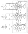
図2は、Uリンクを使用した場合の本発明による放送用送信空中線系システムの実施態様の一例を示す系統図である。これは、6波の放送波を3基の空中線で2波ずつ共用し、共同建設した場合の系統図である。この図は、正常状態におけるUリンク接続の状況を示している。図に示すように、この放送用送信空中線系システムは、系統S1〜S3を具えるものであり、各系統S1〜S3のそれぞれは、上段空中線11、下段空中線12、上段空中線11に接続する上段給電線21、下段空中線12に接続する下段給電線22を具えるものである。各系統S1〜S3の上段および下段空中線11、12の各々は、上段給電線21および下段給電線22を介して、高冗長度切替装置3内のUリンク40に接続している。Uリンク40は、分配器30に接続しており、分配器30は、さらにその他のUリンク40を介して共用装置50に接続している。そして、共用装置50は、さらに、別のUリンク40を介して各チャンネルに接続している。
【0014】
切替による経路変更によって発生する信号出力の変化を抑制するために、各Uリンクの長さを調節することが必要である。
例えば、Uリンク40の長さは、空中線S2について言えば、b2−b6=b5−b6=b4−b6=b7−b6、b3−b4=b4−b8、b1−b2=b2−b9、b3−b4=b4−b11とすることが好適であるが、各Uリンクの長さを全て同じとしても良い。空中線系S1,S3についても同様である。
空中線系S1,S2,S3を相互に接続するため、a8−b7,b8−c7,c8−a7間にUリンク座を設置し、予め相互に接続しておく。こうすることにより、後述するリンクの切替によって各空中線の機能を相互に補完することが可能となる。
【0015】
空中線系S2の上段空中線11、上段給電線21、または分配器30(即ちT分岐)が故障した場合の切替の手法を説明する。
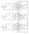
空中線、給電線、共用装置、分配器の各要素のいずれかが故障であると判断した場合、この故障した当該要素を迂回させるために、正常な状態の経路を構成するUリンク40のb1−b2、b3−b4,b5−b6を切り離し、b4−b6間をUリンクで接続することにより、共用装置50の出力を下段空中線12に給電するような経路を構成させる。この場合の経路切替後の空中線システム系統図を図3に示す。図のように、C、Dチャンネルには、下段系の経路を利用して給電可能となる。
逆に、下段系が故障した場合は、同様の手法により、b2−b6間をUリンク(図示しない)で接続し、上段空中線11に給電するような経路を構成させる。なお、切替による経路変更によって発生する信号出力の変化を抑制するために、Uリンク40のb5−b6,b2−b6,b4−b6間の長さを同一にすることが好適である。
【0016】
次に、共用装置50が故障した場合を説明する。例えば、空中線系S2の共用装置50が故障した場合には、Uリンク40のb1−b2,b9−b10,b3−b4、b11−b12を切り離し、b2−b9、b4−b11間をそれぞれUリンクで接続することにより、別の経路を構成させる。共用装置50が故障した場合の経路切替後の空中線システム系統図を図4に示す。このようにリンクを切替えることにより、Cチャンネルからは上段系に給電することができ、また、Dチャンネルからは下段系に給電することができ、従って、放送を継続することができる。
【0017】
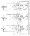
空中線系S2が外的要因などの原因で上下段ともに故障した場合には、Uリンク40のb5−b6を切り離し、b7−b6間をUリンクで接続し、空中線系S1のUリンク40のa3−a4を切り離し、a4−a8間をUリンクで接続すると共に、Uリンクa1−a2,a5−a6を切り離し、a2−a6間をUリンクで接続することにより、冗長な経路を構成させる。空中線系S2が上下段ともに故障した場合の経路切替後の空中線システム系統図を図5に示す。このようにして、AチャンネルおよびBチャンネルは空中線系S1の上段空中線11に、CチャンネルおよびDチャンネルは空中線系S1の下段空中線12に給電することができるようになる。従って、A,B,C,Dのいずれのチャンネルも実用上問題の少ない状態で放送を継続することができる。
なお、空中線系S1,S3が故障した場合にも、上述した手法を用いて、冗長な経路を構成させて実用上問題の少ない状態で放送を継続することができる。
【0018】
この実施態様では、2波を共用した3基の空中線系で構成されるシステムを例として挙げたが、これは例示にすぎないものであり、例えば、3波以上を共用する場合や、空中線の基数を増減した場合にも本発明を適用できることを理解されたい。
さらに、接続部材としてUリンクを挙げたが、これも例示にすぎないものであり、例えば、同軸切替器や無接点切替器など、切替機能を有する類似の装置で代替させることも可能であることを理解されたい。
【0019】
【発明の効果】
本発明による効果を以下にまとめる。
本発明によれば、共用装置を含む共用系の故障時に、当該チャンネルの電波確保が可能となる。
また、本発明によれば、空中線が上下段ともに故障した場合に、簡単な切替え操作で他社の空中線を利用することによって電波確保が可能となる。
さらに、従来は、空中線系が故障した場合に備えるためには、予備空中線を設置するか、他社の空中線と共用するためには、予備共用装置を用意しておく必要があったが、本発明を適用すれば、それらは不要となり経済的である。従って、本発明によれば、冗長度に優れた高信頼性を有する空中線系システムを低コストで実現することが可能となる。
【図面の簡単な説明】
【図1】 本発明による放送用送信空中線系システムを適用した基本的な空中線システム系統図である。
【図2】 Uリンクを使用した場合の本発明による放送用送信空中線系システムの実施態様の一例を示す系統図である。
【図3】 空中線系S2の上段空中線11、上段給電線21、または分配器30(即ちT分岐)が故障した場合の経路切替後の空中線システム系統図である。
【図4】 共用装置50が故障した場合の経路切替後の空中線システム系統図である。
【図5】 空中線系S2が上下段ともに故障した場合の経路切替後の空中線システム系統図である。
【符号の説明】
S1,S2,S3 空中線系
1 空中線
2 給電線
3 高冗長度切替装置
11 上段空中線
12 下段空中線
21 上段給電線
22 下段空中線
30 分配器
40 Uリンク
50 共用装置[0001]
BACKGROUND OF THE INVENTION
The present invention relates to a broadcast transmission aerial system, and in particular, when a failure occurs in an aerial line, a feeder line, a shared device, etc., a state in which there is little practical impact by quickly configuring a redundant path ( The present invention relates to a transmission antenna system for broadcasting including a path switching device capable of continuing broadcasting with an electric field drop of about 3 dB.
[0002]
[Prior art]
Conventionally, this type of switching system supplies power by dividing the aerial line and power supply line into upper and lower parts, and when a failure occurs on one side, it is switched to the normal one by means of the upper and lower power supply changeover panel, which practically affects broadcast services. Some broadcasting stations have adopted a system that can continue broadcasting.
[0003]
However, the conventional method focuses on the aerial line and the power supply line, and sufficient consideration is not given to the case where both the common device that is a common system and the upper and lower aerial lines break down.
[0004]
[Problems to be solved by the invention]
The importance of broadcast radio waves is very important not only for emergency reports during disasters, but also on a daily basis as each company broadcasts 24 hours a day. In particular, in the case of an aerial system, if a failure occurs, it will have a significant impact on the recipient. This is a special high-altitude facility, so it will take time to recover. There is also a great impact on society.
[0005]
For this reason, the aerial redundant system has been improved centering on NHK so far, and the vertical power supply system splits the aerial line together with the power supply line up and down, and if one system fails, the normal one The broadcasting service can be continued within a range where there is no practical problem even if the electric field is somewhat reduced.
[0006]
However, for shared parts such as shared devices, no remedy method has been established for failure, and if both the upper and lower systems fail due to external factors such as strong winds, the conventional technology will provide relief. There is no means.
[0007]
In the future, with the progress of digitalization of terrestrial broadcasts, the number of cases where broadcasters jointly construct a master station is increasing, and at the same time, higher reliability of the antenna system is required.
The present invention also takes into account that each company's antennas can be used with each other, and even if the antenna line, power supply line, etc. fail both vertically or when a shared part such as a shared device fails, a simple switching operation is performed. Thus, it is possible to continue broadcasting within a range where there is no practical problem.
[0008]
[Means for Solving the Problems]
The transmission antenna system for broadcasting according to the first invention of the present invention is:
In a transmission antenna system for broadcasting comprising one antenna system composed of elements of a plurality of antennas, a plurality of feeders, a shared device, and a distributor,
A switching means for automatically or manually disconnecting a link connecting to one or more failed elements and connecting a link only to normal elements of the antenna system elements;
It is characterized by comprising.
Regarding the determination of failure in this case, for example, the system operator can monitor the output signals from each element of a plurality of antennas, a plurality of feeders, a shared device, and a distributor on the display to determine the failure. Alternatively, the facility maintenance staff judges a physical failure such as cutting or breakage from the appearance of each element. As will be described later, instead, it is also possible to detect a failure of each element with a failure detection device or the like.
According to the configuration of the present invention, when an aerial line, an upper or lower stage of a power feed line, a distributor, a shared device, or the like fails, the redundant part is quickly disconnected by using a link that quickly disconnects the failed part and connects to the redundant part path. As a result, broadcasting can be continued in a state where there is little influence on practical use.
[0009]
The broadcast transmission antenna system according to the second invention of the present invention is:
A plurality of the antenna systems;
A link connecting the plurality of antenna systems to each other;
Switching means for disconnecting a link connected to a failed element in the antenna system automatically or manually, and connecting a link to an antenna element other than the failed antenna system;
It is characterized by comprising.
According to the configuration of the present invention, when both the upper and lower tiers of the aerial line or feeder line break down, a redundant system path is secured by connecting to the upper or lower tier of the other company's aerial system, and broadcasting is performed in a state where there is little practical impact. Can continue.
[0010]
Furthermore, the following structures are also considered as a modification of this invention.
A broadcast transmission antenna system according to a third invention of the present invention is:
Determine whether each element is normal based on at least the output signal from each element of the antenna, feeder, shared device, and distributor, and a predetermined threshold set for each of these elements Failure detection means for detecting a failure;
When it is determined that one or more elements are not normal in the failure detection means, a link connected to the element determined to be abnormal is disconnected automatically or manually, and the antenna system element is normal A switching means for connecting a link only to a new element,
It is characterized by comprising.
According to this configuration, it is possible to automatically detect a failed element quickly and switch to a normal element when a failure occurs. The detection of the failure can be judged only from the output signal from each element without setting a threshold value.
[0011]
A broadcast transmission antenna system according to a fourth invention of the present invention is:
Multiple antenna systems,
A link connecting the plurality of antenna systems to each other;
When it is determined by the failure detection means that one or more elements in the antenna system are not normal, a link that connects to the failed element in the antenna system that is determined to be abnormal normally or manually Switching means for disconnecting and connecting a link to an antenna element other than the antenna system determined to be abnormal is provided.
According to this configuration, it is possible to automatically detect a failed element immediately at the time of a failure and switch to a normal antenna system element.
Although the solving means has been described as an apparatus, it should be understood that the present invention includes methods corresponding to these, a program that realizes these means, a storage medium that records the program, and the like.
[0012]
DETAILED DESCRIPTION OF THE INVENTION
Hereinafter, embodiments of the present invention will be described in detail with reference to the accompanying drawings.
FIG. 1 is a basic antenna system diagram to which a broadcast antenna system for broadcasting according to the present invention is applied. This system system includes systems S1 to Sn, and each of the systems S1 to Sn includes an up-and-down-
The high
In FIG. 1, for convenience of explanation, all channels are integrated in an integrated manner. However, in reality, each broadcasting company sharing a high-redundancy antenna switching device switches switching channels for each system. And connect them together to complete the system.
[0013]
FIG. 2 is a system diagram showing an example of an embodiment of a broadcast transmission antenna system according to the present invention when a U link is used. This is a system diagram in the case where 6 broadcast waves are shared by 3 aerials and 2 waves are shared for joint construction. This figure shows the state of the U link connection in the normal state. As shown in the figure, this broadcast transmission aerial system includes systems S1 to S3, and each of the systems S1 to S3 is connected to an upper
[0014]
It is necessary to adjust the length of each U link in order to suppress a change in signal output caused by a path change due to switching.
For example, the length of the
In order to connect the antenna systems S1, S2, and S3 to each other, U link seats are installed between a8-b7, b8-c7, and c8-a7, and are connected to each other in advance. By doing so, it is possible to complement the functions of the antennas by switching the links described later.
[0015]
A switching method when the
When it is determined that any one of the elements of the antenna line, the feeder line, the shared device, and the distributor is a failure, in order to bypass the failed element, b1- of the
On the other hand, when the lower system fails, a path that feeds power to the
[0016]
Next, a case where the shared
[0017]
When both the upper and lower stages of the antenna system S2 fail due to external factors, b5-b6 of the
Even when the antenna systems S1 and S3 are out of order, the above-described method can be used to construct a redundant route and continue broadcasting in a state where there are few practical problems.
[0018]
In this embodiment, a system composed of three antenna systems sharing two waves has been described as an example, but this is merely an example. For example, when three or more waves are shared, It should be understood that the present invention can be applied even when the radix is increased or decreased.
Furthermore, although the U link has been mentioned as the connecting member, this is also merely an example, and it can be replaced with a similar device having a switching function, such as a coaxial switch or a non-contact switch, for example. I want you to understand.
[0019]
【The invention's effect】
The effects of the present invention are summarized below.
According to the present invention, radio waves can be secured on the channel when a shared system including a shared device fails.
Further, according to the present invention, when the antenna fails in both the upper and lower stages, radio waves can be secured by using the other company's antenna with a simple switching operation.
Further, conventionally, in order to prepare for a case where the antenna system breaks down, it is necessary to prepare a standby shared device in order to install a standby antenna or to share it with another company's antenna. If they are applied, they are unnecessary and economical. Therefore, according to the present invention, it is possible to realize an antenna system having high redundancy and high reliability at low cost.
[Brief description of the drawings]
FIG. 1 is a basic antenna system diagram to which a broadcast antenna system for broadcasting according to the present invention is applied.
FIG. 2 is a system diagram showing an example of an embodiment of a broadcast transmitting antenna system according to the present invention when a U link is used.
FIG. 3 is a system diagram of the antenna system after path switching when the
FIG. 4 is a system diagram of an antenna system after path switching when a shared
FIG. 5 is a system diagram of an antenna system after path switching when the antenna system S2 fails in both upper and lower stages;
[Explanation of symbols]
S1, S2,
Claims (2)
自動、或いは、手動により、故障した1つまたは複数の前記要素と接続するリンクを切り離し、前記空中線系の要素の正常な要素のみにリンクを接続する切替手段、
を具えること特徴とする放送用送信空中線系システム。In a transmission antenna system for broadcasting comprising one antenna system composed of elements of a plurality of antennas, a plurality of feeders, a shared device, and a distributor,
A switching means for automatically or manually disconnecting a link connecting to one or more failed elements and connecting a link only to normal elements of the antenna system elements;
A transmission antenna system for broadcasting characterized by comprising:
複数の前記空中線系と、
前記複数の空中線系を相互に接続するリンクと、
自動、或いは、手動により、前記空中線系における故障した要素と接続するリンクを切り離し、この故障した空中線系以外の空中線系の要素へリンクを接続する切替手段と、
を具えることを特徴とするシステム。The system of claim 1, wherein
A plurality of the antenna systems;
A link connecting the plurality of antenna systems to each other;
Switching means for disconnecting a link connected to a failed element in the antenna system automatically or manually, and connecting a link to an antenna element other than the failed antenna system;
A system characterized by comprising.
Priority Applications (1)
| Application Number | Priority Date | Filing Date | Title |
|---|---|---|---|
| JP2001136323A JP3829068B2 (en) | 2001-05-07 | 2001-05-07 | Broadcasting antenna system for broadcasting |
Applications Claiming Priority (1)
| Application Number | Priority Date | Filing Date | Title |
|---|---|---|---|
| JP2001136323A JP3829068B2 (en) | 2001-05-07 | 2001-05-07 | Broadcasting antenna system for broadcasting |
Publications (2)
| Publication Number | Publication Date |
|---|---|
| JP2002335123A JP2002335123A (en) | 2002-11-22 |
| JP3829068B2 true JP3829068B2 (en) | 2006-10-04 |
Family
ID=18983622
Family Applications (1)
| Application Number | Title | Priority Date | Filing Date |
|---|---|---|---|
| JP2001136323A Expired - Fee Related JP3829068B2 (en) | 2001-05-07 | 2001-05-07 | Broadcasting antenna system for broadcasting |
Country Status (1)
| Country | Link |
|---|---|
| JP (1) | JP3829068B2 (en) |
-
2001
- 2001-05-07 JP JP2001136323A patent/JP3829068B2/en not_active Expired - Fee Related
Also Published As
| Publication number | Publication date |
|---|---|
| JP2002335123A (en) | 2002-11-22 |
Similar Documents
| Publication | Publication Date | Title |
|---|---|---|
| US9509937B2 (en) | Aircraft in-flight entertainment system with a distributed memory and associated methods | |
| US8081933B2 (en) | Reconfigurable aircraft radio communications system | |
| US20060234700A1 (en) | Aircraft in-flight entertainment system including digital radio service and associated methods | |
| US9049037B2 (en) | Method and system for monitoring and encoding signals in a local facility and communicating the signals between a local collection facility and a remote facility using an IP network | |
| US8776146B2 (en) | Aircraft in-flight entertainment system including a distributed digital radio service and associated methods | |
| US20030185150A1 (en) | Monitoring and control system | |
| EP1199816A1 (en) | Radio base station and method of preventing failure of radio function | |
| US20230074318A1 (en) | Switching radiofrequency chains | |
| US7171173B2 (en) | Redundant GPS antenna splitter | |
| JP3829068B2 (en) | Broadcasting antenna system for broadcasting | |
| CN111934900A (en) | Emergency system and method for switching intermediate frequency through modulator | |
| US20110069608A1 (en) | System for providing backup programming at radio or television transmitter | |
| JP2551042B2 (en) | Automatic switching device for transmission trunk line in CATV system | |
| JP2854540B2 (en) | Cable television system | |
| EP1240792B1 (en) | Procedure and arrangement to make redundancy for a radio communication system | |
| JP2682514B2 (en) | Receive hot standby system | |
| CN224054317U (en) | Satellite information source networking device between wireless stations | |
| JP3831240B2 (en) | Broadcasting antenna system for broadcasting | |
| KR101015939B1 (en) | MHC optical signal switching device | |
| JP2005354465A (en) | Radio relay system for broadcasting stations | |
| JPH0884100A (en) | Satellite communication system | |
| JP3686759B2 (en) | Transmission system switching system and switching method | |
| JPH08125594A (en) | Power supply switching circuit for relay device | |
| JPH0535931B2 (en) | ||
| JP2669345B2 (en) | Satellite broadcasting system |
Legal Events
| Date | Code | Title | Description |
|---|---|---|---|
| A621 | Written request for application examination |
Free format text: JAPANESE INTERMEDIATE CODE: A621 Effective date: 20041005 |
|
| A977 | Report on retrieval |
Free format text: JAPANESE INTERMEDIATE CODE: A971007 Effective date: 20060228 |
|
| A131 | Notification of reasons for refusal |
Free format text: JAPANESE INTERMEDIATE CODE: A131 Effective date: 20060307 |
|
| TRDD | Decision of grant or rejection written | ||
| A01 | Written decision to grant a patent or to grant a registration (utility model) |
Free format text: JAPANESE INTERMEDIATE CODE: A01 Effective date: 20060613 |
|
| A61 | First payment of annual fees (during grant procedure) |
Free format text: JAPANESE INTERMEDIATE CODE: A61 Effective date: 20060710 |
|
| R150 | Certificate of patent or registration of utility model |
Free format text: JAPANESE INTERMEDIATE CODE: R150 |
|
| FPAY | Renewal fee payment (event date is renewal date of database) |
Free format text: PAYMENT UNTIL: 20100714 Year of fee payment: 4 |
|
| FPAY | Renewal fee payment (event date is renewal date of database) |
Free format text: PAYMENT UNTIL: 20100714 Year of fee payment: 4 |
|
| FPAY | Renewal fee payment (event date is renewal date of database) |
Free format text: PAYMENT UNTIL: 20110714 Year of fee payment: 5 |
|
| LAPS | Cancellation because of no payment of annual fees |