JP3832003B2 - Air preheater element changer - Google Patents
Air preheater element changer Download PDFInfo
- Publication number
- JP3832003B2 JP3832003B2 JP35058596A JP35058596A JP3832003B2 JP 3832003 B2 JP3832003 B2 JP 3832003B2 JP 35058596 A JP35058596 A JP 35058596A JP 35058596 A JP35058596 A JP 35058596A JP 3832003 B2 JP3832003 B2 JP 3832003B2
- Authority
- JP
- Japan
- Prior art keywords
- conveyor
- low temperature
- air preheater
- lifter
- tray
- Prior art date
- Legal status (The legal status is an assumption and is not a legal conclusion. Google has not performed a legal analysis and makes no representation as to the accuracy of the status listed.)
- Expired - Fee Related
Links
Images



Classifications
-
- Y—GENERAL TAGGING OF NEW TECHNOLOGICAL DEVELOPMENTS; GENERAL TAGGING OF CROSS-SECTIONAL TECHNOLOGIES SPANNING OVER SEVERAL SECTIONS OF THE IPC; TECHNICAL SUBJECTS COVERED BY FORMER USPC CROSS-REFERENCE ART COLLECTIONS [XRACs] AND DIGESTS
- Y02—TECHNOLOGIES OR APPLICATIONS FOR MITIGATION OR ADAPTATION AGAINST CLIMATE CHANGE
- Y02E—REDUCTION OF GREENHOUSE GAS [GHG] EMISSIONS, RELATED TO ENERGY GENERATION, TRANSMISSION OR DISTRIBUTION
- Y02E20/00—Combustion technologies with mitigation potential
- Y02E20/34—Indirect CO2mitigation, i.e. by acting on non CO2directly related matters of the process, e.g. pre-heating or heat recovery
Landscapes
- Air Supply (AREA)
Description
【0001】
【発明の属する技術分野】
本発明は、空気予熱器のエレメント交換装置に関するものである。
【0002】
【従来の技術】
図6は従来のツインフロー型の空気予熱器の一例を示したもので、円盤形状を有するエレメント装置1の上部に設けられた上部ケーシング2内に、上部フード3が回転可能に備えられていると共に、エレメント装置1の下部に設けられた下部ケーシング4内に、下部フード5が回転可能に備えられている。
【0003】
前記上部フード3及び下部フード5は、夫々図7に示すように平面形状が蝶形を有しており、上部フード3と下部フード5とは、中心に設けられた回転軸6により一体に回転するようになっている。図6中7は下部フード5の外周に取付けた大歯車、8は前記大歯車7に噛合するホイール9を介して前記下部フード5、回転軸6及び上部フード3を回転する駆動モータ、10は回転継手部を示す。
【0004】
更に、前記上部フード3と下部フード5は、夫々内部を半径方向に区画するようにした内側の第1フード3a,5aと外側の第2フード3b,5bとを備えている。
【0005】
ボイラ等からの排ガス11は、前記上部ケーシング2の内側に供給されて、前記蝶形の上部フード3外側の高温側ガス空間12A(図7参照)を経てエレメント装置1を加熱しながら下方に流動し、蝶形の下部フード5外側の低温側ガス空間12Bから下流に導かれるようになっている。前記低温側ガス空間12Bは、図6に示すように、ガススプリッター12aにより半径方向に区画されており、前記排ガス11はガススプリッター12aにより区画されて下流に導かれるようになっている。
【0006】
また、前記下部フード5の第1フード5a内に供給された一次空気13aは、前記排ガス11の流動によって加熱されたエレメント装置1内を上方に流動することにより加熱された後、上部フード3の第1フード3a内に導かれ、また、前記下部フード5の第2フード5b内に供給された二次空気13bは、エレメント装置1内を上方に流動して加熱された後、上部フード3の第2フード3b内に導かれるようになっている。
【0007】
前記エレメント装置1は、図6及び図7に示すように、円盤形状の内部を周方向と半径方向とに多数に区画する支持枠14を備えており、該支持枠14によって区画された空間の夫々に、エレメント15を複数段(図6では3段)に挿入して積層し、下部に備えた固定ストッパ16により支持するようにした構成を有しており、前記エレメント15は、高温の排ガス11が上方から下方に向って流動するために、上段が高温部エレメント15a、中段が中温部エレメント15b、下段が低温部エレメント15cと呼ばれている。図中17は空気予熱器である。
【0008】
微粉炭或いは重油等のように硫黄分が含有された燃料を燃焼した後のボイラ等の排ガス11を前記空気予熱器17に導いて熱交換をする場合には、500℃前後で導入されてきた排ガス11がエレメント装置1のエレメント15で冷却されて排ガス11の温度が130℃前後に低下されることによって、排ガス11中の硫黄分が排ガス11中の水分と共に亜硫酸塩を形成して特に低温部エレメント15cに結露し、このために低温部エレメント15cが著しく腐食するという問題があった。
【0009】
このように、腐食したエレメント15は交換する必要があるが、前記したように低温部エレメント15cの交換頻度は、他の高温部エレメント15a、及び中温部エレメント15bに対して非常に多くなっている。
【0010】
従来において前記腐食した低温部エレメント15cを交換する際には、図6及び図7に示すように、空気予熱器17内に備えられている図示しないスートブロワ等の交換作業の障害となるものを除去した後、高温側ガス空間12Aに位置するように、前記上部フード3に支持ビーム18を取付け、該支持ビーム18に備えたチェーンブロック19を用いて、上部の高温部エレメント15a、及び中温部エレメント15bを順次吊り上げて取除いた後、低温部エレメント15cを吊り上げ、上部ケーシング2に備えたマンホール20から空気予熱器17の外部に取出し、続いて新たな低温部エレメント15cを空気予熱器17内に搬入して、前記と同様にチェーンブロック19を用いてエレメント装置1の支持枠14内に吊り下げて挿入することにより固定ストッパ16上に固定し、その後前記中温部エレメント15b、及び高温部エレメント15aを順次吊り降ろして固定し、以後上記操作を図7に示した半径方向のエレメント15について行い、続いて上部フード3を所要角度旋回させた後、更に上記操作を繰返すことにより、順次交換を行うようにしている。
【0011】
【発明が解決しようとする課題】
しかし、上記従来のエレメント交換装置においては、低温部エレメント15cの交換に際し、高温部エレメント15a、及び中温部エレメント15bを取除いた後でなければ、低温部エレメント15cの交換を行うことができないため、エレメント15の交換作業が煩雑で、交換作業に長い時間がかかり、且つエレメント装置1に備えられるエレメント15数が非常に多いために、エレメント15の交換作業に要する工期が長期化してしまうという問題を有していた。
【0012】
また、チェーンブロック19にて吊り上げたエレメント15をマンホール20位置に移動させて、マンホール20から上部ケーシング2外部に取出す作業、及び逆にエレメント15を上部ケーシング2外部からマンホール20を経て内部に搬入してチェーンブロック19により吊り下げるという作業が非常に大変で時間が掛かり、また作業に危険を伴うという問題を有していた。
【0013】
本発明は、かかる従来の問題点を解決すべくなしたもので、他のエレメントを除去することなく低温部エレメントのみを容易且つ迅速に交換することができるようにした空気予熱器のエレメント交換装置を提供することを目的としている。
【0014】
【課題を解決するための手段】
請求項1に記載の発明は、複数段の下部が低温部エレメントになっており下側に着脱可能に取付けられた係止具により支持枠に支持されるようになっているエレメント装置の下部に、低温側ガス空間において、エレメントが通過できる間隔を有して空気予熱器の半径方向に平行に延びて下部フードに取付られたコンベヤと、
該コンベヤ上に跨がって走行が可能な支持台と、該支持台の内側にコンベヤの間隔内を昇降できるように区画して該支持台に着脱可能に取付けられ且つ内側に開口が形成されたエレメント受皿とを備えたエレメント移動台と、
前記コンベヤに走行可能に吊り下げられた走行台と、該走行台の下部に備えた油圧シリンダにより前記エレメント受皿の開口内を昇降し得る昇降台とを備えたエレメント抜差し装置と、
下部ケーシングの内周下部に内側に向って張出した作業床と、
該作業床上に周方向に設置したレールに沿って走行が可能で且つ前記コンベヤの間隔内を昇降して前記エレメント受皿を受けることができる短コンベヤを上面に備えたリフターと、
前記下部ケーシングの周方向所要位置に設けられたマンホールの内側下部に貫通配置した受渡しコンベヤと、
を備えたことを特徴とする空気予熱器のエレメント交換装置、に係るものである。
【0015】
請求項2に記載の発明は、上面に受渡し短コンベヤを昇降可能に備え、キャスターにより作業床面上を走行して、リフターと受渡しコンベヤとの間のエレメントの受渡しを行うリフトトラックを備えたことを特徴とする請求項1に記載の空気予熱器のエレメント交換装置、に係るものである。
【0016】
請求項1に記載の発明では、エレメント装置の下部に備えられていて腐食しやすい低温部エレメントを、低温側ガス空間に備えたコンベヤ、エレメント移動台、エレメント抜差し装置、リフター、及びマンホールに備えた受渡しコンベヤを介して、エレメント装置の下側から取出して空気予熱器の外部に搬出したり、また新たな低温部エレメントを前記エレメント装置に下側から取付けるようにしているので、エレメントの交換作業を能率的にしかも安全に行うことができる。
【0017】
請求項2に記載の発明では、作業床上を自由に走行して、リフターと受渡しコンベヤとの間の低温部エレメントの受渡しを行えるようにしたリフトトラックを備えているので、リフターがマンホールに設けられた受渡しコンベヤ位置まで走行して低温部エレメントを運んで行ったり、またリフターが受渡しコンベヤに低温部エレメントを受取りに行く時間が節約でき、エレメントの交換作業の能率を更に向上させることができる。
【0018】
【発明の実施の形態】
以下、本発明の実施の形態を、図示例と共に説明する。
【0019】
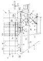
図1〜図4は、請求項1に記載の発明を実施する形態の一例を示したもので、エレメント15が3段に備えられて上段が高温部エレメント15a、中段が中温部エレメント15b、下段が低温部エレメント15cとなっているエレメント装置1の支持枠14の下側に、低温部エレメント15cを支持するようにした係止具21を着脱可能に取付ける。
【0020】
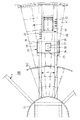
更に、前記エレメント装置1下部における低温側ガス空間12B(図6参照)に、図2に示すように、エレメント15が通過できる間隔Lを有して空気予熱器17の半径方向に平行に延びるコンベヤ22,22を設置する。該コンベヤ22,22は、低温部エレメント15cを電動にて自由に搬送できるように前記エレメント装置1の下面との間に所要の間隔を有して備えられており、内側端部が内側回転体23に取付けられ、外側端部が前記大歯車7に取付けられていて前記下部フード5と一緒に回転するようになっている。この時、低温側ガス空間12Bに設けられているガススプリッター12aが、前記コンベヤ22,22の設置の邪魔になるので、破線で示す部分12a’を仮撤去するようにしている。
【0021】
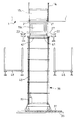
前記コンベヤ22,22上に、図3に示すように、エレメント移動台24を設ける。エレメント移動台24は、コンベヤ22,22上に跨がって走行できるようにした支持台25を備えており、該支持台25は、その内側がコンベヤ間隔L内を昇降できる大きさに区画され、且つ前記支持台25に対してピン或いはボルト等の着脱具26により着脱できるようにしたエレメント受皿27を備えている。更に、エレメント受皿27の内側には開口28(図2、図3)が形成されている。
【0022】
前記コンベヤ22,22にエレメント抜差し装置29を設ける。エレメント抜差し装置29は、図3に示すように、コンベヤ22,22の下部に吊下ローラ30を介して走行可能に吊り下げられた走行台31を備えており、該走行台31には、前記エレメント受皿27の内側に形成した開口28内を下部に備えた油圧シリンダ32により昇降できるようにした昇降台33を備えている。前記走行台31におけるコンベヤ22,22の外側位置には、支持材34を介してエレメント装置1の下面に小さい隙間で接近するようにした受け部材35が取付けられている。
【0023】
下部ケーシング4の下部内周には、内側に向って張出した作業床36を設置し、該作業床36上に、空気予熱器17の周方向にレール37を設置して、該レール37上にリフター38を走行可能に設置する。
【0024】
リフター38は、図1及び図3に示すように、油圧シリンダ39により上下に伸縮するリンク機構40の上端に、前記コンベヤ22,22の間隔L内を昇降可能にして前記エレメント受皿27を受けられるようにした電動の短コンベヤ41を備えた昇降台42を取付けている。
【0025】
更に、前記下部ケーシング4の周方向所要位置に設けられたマンホール43(例えば4箇所)の内側下部には、内側端が前記リフター38の短コンベヤ41と接近するようにした電動の受渡しコンベヤ44を貫通させて設けている。図中45は下部ケーシング4の外部における前記受渡しコンベヤ44の上側に設けたホイスト46を備えたモノレールである。また、図1、図3、図4に示すように、前記コンベヤ22,22の下部の前記受渡しコンベヤ44と同じ高さ位置には、内側端が内側回転体23に固定され、外側端が前記大歯車7に支持部材47を介して支持された作業足場48を設けている。
【0026】
以下、上記図1〜図4に示した実施の形態例の作用を説明する。
【0027】
低温部エレメント15cの交換を行う際には、図1に示すように、ガススプリッター12aの破線で示す部分12a’を仮撤去した後、コンベヤ22,22及び作業足場48をマンホール43から低温側ガス空間12Bに搬入して下部フード5に取付け、前記コンベヤ22,22上にエレメント移動台24のエレメント受皿27上に載置すると共に、エレメント抜差し装置29を設置する。更に、下部ケーシング4の下部内周に作業床36を設置して該作業床36上に周方向に延びるレール37を設け、該レール37上にリフター38を設置する。また、下部ケーシング4に備えられたマンホール43の内側下部に、該マンホール43を貫通するように受渡しコンベヤ44を配置する。
【0028】
上記した構成とした後、まず、前記エレメント移動台24とエレメント抜差し装置29を、交換する低温部エレメント15cの直下位置に移動させた後、油圧シリンダ32を伸張させることにより昇降台33をエレメント受皿27の開口28を通って上昇させて低温部エレメント15cの下側に接触させる。
【0029】
この状態で係止具21を取外すことにより低温部エレメント15cを昇降台33上に載置させる。
【0030】
この時、低温部エレメント15cは、通常、排ガス11内のダストの堆積と腐食とによって支持枠14に固着されて一体化し取出すのが困難なので、図3に示すようにボルト或いはピン等の連結具33aにより前記昇降台33と低温部エレメント15cとを連結する。
【0031】
続いて、前記油圧シリンダ32を縮小すると、低温部エレメント15cが支持枠14から引抜かれて図3に示すようにエレメント移動台24に載置される。前記低温部エレメント15cを支持枠14から引抜く時の反力は、支持材34及び受け部材35を介してエレメント装置1の下面で受けることができる。
【0032】
次に連結具33aを取外して低温部エレメント15cと昇降台33の連結を解いて昇降台33を下降させると、低温部エレメント15cが載置されたエレメント移動台24をエレメント抜差し装置29とは別個に走行できるようになるので、該エレメント移動台24を前記リフター38の直上に移動させる。
【0033】
続いて、リフター38の油圧シリンダ39を伸張することによりリンク機構40を上方に伸張させ、昇降台42の短コンベヤ41を前記エレメント移動台24の下面に接触させる。
【0034】
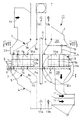
続いて、着脱具26を取外してエレメント移動台24の支持台25とエレメント受皿27との連結を解く。するとエレメント受皿27に載置された低温部エレメント15cは図4に示すようにリフター38の短コンベヤ41上に支持されるようになるので、油圧シリンダ39を縮小してリフター38の支持台25を下降させる。
【0035】
前記コンベヤ22,22の外側延長上にマンホール43が位置していないときは、前記短コンベヤ41上に支持された低温部エレメント15cを作業足場48の下側まで下降させた後、リフター38をレール37に沿ってマンホール43の位置まで走行させ、前記短コンベヤ41が図1に仮想線で示すようにマンホール43に設けた受渡しコンベヤ44と同一の高さになるようにする。
【0036】
すると、前記短コンベヤ41上の低温部エレメント15cを、受渡しコンベヤ44により下部ケーシング4の外部に移動させることができ、従って空気予熱器17の外部に設けられたモノレール45のホイスト46により吊り上げて、所要位置に搬送することができる。
【0037】
前記エレメント移動台24上に次の低温部エレメント15cを取出すには、前記した取出時に支持台25からエレメント受皿27が取外されているので、支持台25に、別のエレメント受皿27を取付けておく。
【0038】
また、新たな低温部エレメント15cをエレメント装置1に取付ける際は、前述と逆の手順によって行う。
【0039】
即ち、エレメント受皿27に載置された低温部エレメント15cを受渡しコンベヤ44から下部ケーシング4内に搬入し、続いて該低温部エレメント15cをリフター38の短コンベヤ41上に移動させる。
【0040】
次に、エレメント受皿27を有していない支持台25をリフター38の直上に移動させ、リフター38を上昇させることにより支持台25の内側に、低温部エレメント15cが載置されたエレメント受皿27を嵌合させ、支持台25とエレメント受皿27とを着脱具26により固定する。
【0041】
続いて、前記低温部エレメント15cが載置されたエレメント移動台24とエレメント抜差し装置29を、エレメント装置1の低温部エレメント15cを取付ける位置の直下に移動した後、油圧シリンダ32を伸張させて低温部エレメント15cを押上げることにより低温部エレメント15cを支持枠14内に押込み、その後挿入された低温部エレメント15cの下部に係止具21を取付ける。
【0042】
低温部エレメント15cの交換作業が終了すると、前記したように低温側ガス空間12Bに備えたコンベヤ22,22、エレメント移動台24、エレメント抜差し装置29、リフター38、作業床36、作業足場48、受渡しコンベヤ44等を撤去してマンホール43から空気予熱器17の外部に取り出した後、前記ガススプリッター12aから仮撤去した破線の部分12a’を取付けることにより、作業を終了する。
【0043】
前記した低温部エレメント15cに対して交換頻度が少ない高温部エレメント15a及び中温部エレメント15bの交換は、図6及び図7に示した従来と同様の方法によって行うことができる。
【0044】
上記したように、エレメント装置1の下部に備えられている低温部エレメント15cを、低温側ガス空間12Bに備えたコンベヤ22,22、エレメント移動台24、エレメント抜差し装置29、リフター38、及びマンホール43に備えた受渡しコンベヤ44を介して、エレメント装置1の下側から取出して空気予熱器17の外部に搬出したり、また新しい低温部エレメント15cを前記エレメント装置1に下側から取付けるようにしているので、エレメント15の交換作業を能率的にしかも安全に行うことができる。
【0045】
図5は、請求項2に記載の発明を実施する形態の一例を示したもので、基本構成は前記図1〜図4の場合と同様であるが、前記作業床36上に、リフトトラック49を備えている点のみが相違している。
【0046】
リフトトラック49は、リンク機構50により昇降する昇降台51が上端に備えられていて該昇降台51に受渡し短コンベヤ52が備えられており、更にリフトトラック49はキャスター53によって作業床36面を自由に走行して、前記リフター38と受渡しコンベヤ44との間での低温部エレメント15cの受渡しができるようになっている。
【0047】
図5に示したように、作業床36上にリフトトラック49を備えていると、低温部エレメント15cを受渡しコンベヤ44上に取出す際に、リフター38上に支持した低温部エレメント15cをリフトトラック49に受渡した後は、直ちにコンベヤ22,22上に取出された次の低温部エレメント15cを受取りに行くことができ、この間にリフトトラック49が受渡しコンベヤ44位置まで走行して、前記受け渡された低温部エレメント15cを受渡しコンベヤ44に送り出すことができ、よって、リフター38の走行時間を節約して低温部エレメント15cの取出作業を更に能率的に行うことができ、また新たな低温部エレメント15cを取付ける際にも、リフター38が受渡しコンベヤ44位置まで低温部エレメント15cを受取りに行く必要がなく、新たな低温部エレメント15cを運んできてリフター38の側部で待機しているリフトトラック49から低温部エレメント15cを受取ればよいので、低温部エレメント15cの取付作業も能率的に行うことができる。
【0048】
【発明の効果】
請求項1に記載の発明によれば、エレメント装置の下部に備えられている低温部エレメントを、低温側ガス空間に備えたコンベヤ、エレメント移動台、エレメント抜差し装置、リフター、及びマンホールに備えた受渡しコンベヤを介して、エレメント装置の下側から取出して空気予熱器の外部に搬出したり、また新たな低温部エレメントを前記エレメント装置に下側から取付けるようにしているので、エレメントの交換作業を能率的にしかも安全に行うことができるという優れた効果を奏し得る。
【0049】
請求項2に記載の発明によれば、作業床上を自由に走行して、リフターと受渡しコンベヤとの間の低温部エレメントの受渡しを行えるようにしたリフトトラックを備えているので、リフターがマンホールに設けられた受渡しコンベヤ位置まで走行して低温部エレメントを運んで行ったり、またリフターが受渡しコンベヤに低温部エレメントを受取りに行く時間が節約でき、エレメントの交換作業の能率を更に向上させることができる効果がある。
【図面の簡単な説明】
【図1】請求項1に記載の発明を実施する形態の一例を示すもので、図6のI部分の拡大側面図である。
【図2】図1のII−II方向矢視図である。
【図3】図1のIII−III方向矢視図である。
【図4】図1のIV−IV方向矢視図である。
【図5】請求項2に記載の発明を実施する形態の一例を示す図1と同様の拡大側面図である。
【図6】空気予熱器に備えられた従来装置の一例を示す切断側面図である。
【図7】図6のVII−VII方向矢視図である。
【符号の説明】
1 エレメント装置
4 下部ケーシング
5 下部フード
12B 低温側ガス空間
15 エレメント
15c 低温部エレメント
17 空気予熱器
21 係止具
22 コンベヤ
24 エレメント移動台
25 支持台
27 エレメント受皿
28 開口
29 エレメント抜差し装置
31 走行台
32 油圧シリンダ
33 昇降台
36 作業床
37 レール
38 リフター
41 短コンベヤ
43 マンホール
44 受渡しコンベヤ
49 リフトトラック
52 受渡し短コンベヤ
53 キャスター
L コンベヤ間隔[0001]
BACKGROUND OF THE INVENTION
The present invention relates to an element exchange device for an air preheater.
[0002]
[Prior art]
FIG. 6 shows an example of a conventional twin flow type air preheater, and an
[0003]
The
[0004]
Furthermore, the
[0005]
[0006]
The
[0007]
As shown in FIGS. 6 and 7, the
[0008]
When
[0009]
Thus, although the corroded
[0010]
Conventionally, when replacing the corroded
[0011]
[Problems to be solved by the invention]
However, in the above-described conventional element exchange device, when the
[0012]
The
[0013]
The present invention has been made to solve the above-mentioned conventional problems, and it is possible to easily and quickly replace only the low temperature element without removing other elements, and an element replacement device for an air preheater. The purpose is to provide.
[0014]
[Means for Solving the Problems]
According to the first aspect of the present invention, the lower part of the plurality of steps is a low-temperature part element, and the lower part of the element device is supported by the support frame by a locking tool detachably attached to the lower side. A conveyor attached to the lower hood and extending parallel to the radial direction of the air preheater with an interval through which the elements can pass in the low temperature side gas space;
A support base that can run over the conveyor, and a partition that can be moved up and down within the interval of the conveyor inside the support base, is detachably attached to the support base, and an opening is formed inside. An element moving table equipped with an element receiving tray,
An element insertion / removal device comprising a traveling platform suspended to be able to travel on the conveyor, and a lifting platform capable of moving up and down in the opening of the element tray by a hydraulic cylinder provided at a lower portion of the traveling platform;
A work floor projecting inward to the lower inner periphery of the lower casing;
A lifter provided with a short conveyor on the upper surface, which is capable of traveling along rails installed in the circumferential direction on the work floor and capable of receiving the element tray by moving up and down within the interval of the conveyor;
A delivery conveyor disposed penetrating the inner lower portion of a manhole provided at a required position in the circumferential direction of the lower casing;
It is related with the element exchange apparatus of the air preheater characterized by including.
[0015]
The invention according to
[0016]
In the first aspect of the present invention, the low temperature element, which is provided at the lower part of the element device and easily corrodes, is provided in a conveyor, an element moving table, an element inserting / removing device, a lifter, and a manhole provided in the low temperature side gas space. It is taken out from the lower side of the element device via the delivery conveyor and carried out of the air preheater, and a new low temperature element is attached to the element device from the lower side. It can be done efficiently and safely.
[0017]
In the second aspect of the invention, the lift truck is provided in the manhole because the lift truck is provided so that it can freely travel on the work floor and deliver the low temperature element between the lifter and the delivery conveyor. In addition, it is possible to save time when the low temperature element is carried by traveling to the delivery conveyor position, and when the lifter takes the low temperature element to the delivery conveyor, and the efficiency of element replacement work can be further improved.
[0018]
DETAILED DESCRIPTION OF THE INVENTION
Hereinafter, embodiments of the present invention will be described with reference to the drawings.
[0019]
1 to 4 show an example of an embodiment for carrying out the invention described in
[0020]
Furthermore, the low temperature
[0021]
As shown in FIG. 3, an element moving table 24 is provided on the
[0022]
An element insertion /
[0023]
On the lower inner periphery of the lower casing 4, a
[0024]
As shown in FIGS. 1 and 3, the
[0025]
Furthermore, an
[0026]
The operation of the embodiment shown in FIGS. 1 to 4 will be described below.
[0027]
When replacing the
[0028]
After the above-described configuration, first, the
[0029]
In this state, the low
[0030]
At this time, the low
[0031]
Subsequently, when the
[0032]
Next, when the connecting
[0033]
Subsequently, by extending the
[0034]
Subsequently, the
[0035]
When the
[0036]
Then, the low
[0037]
In order to take out the next
[0038]
Moreover, when attaching the new low
[0039]
That is, the low
[0040]
Next, the
[0041]
Subsequently, after the
[0042]
When the replacement operation of the
[0043]
The replacement of the high-
[0044]
As described above, the low
[0045]
FIG. 5 shows an example of an embodiment for carrying out the invention according to
[0046]
The
[0047]
As shown in FIG. 5, when the
[0048]
【The invention's effect】
According to the first aspect of the present invention, the low temperature element provided in the lower part of the element device is provided in the conveyor, element moving table, element inserting / removing device, lifter, and manhole provided in the low temperature side gas space. Take out from the lower side of the element device via the conveyor and take it out of the air preheater. Also, a new low temperature element is attached to the element device from the lower side. In addition, an excellent effect that it can be performed safely can be achieved.
[0049]
According to the second aspect of the present invention, since the lift truck that freely travels on the work floor and enables the delivery of the low temperature element between the lifter and the delivery conveyor is provided, the lifter is disposed in the manhole. Traveling to the position of the delivery conveyor provided to carry the low-temperature part element, and the time required for the lifter to receive the low-temperature part element to the delivery conveyor can be saved, further improving the efficiency of element replacement work. effective.
[Brief description of the drawings]
FIG. 1 is an enlarged side view of a portion I in FIG. 6, showing an example of an embodiment for carrying out the invention according to
FIG. 2 is a view taken in the direction of arrows II-II in FIG.
3 is a view taken in the direction of arrows III-III in FIG.
4 is a view taken in the direction of arrows IV-IV in FIG. 1;
5 is an enlarged side view similar to FIG. 1, showing an example of an embodiment for carrying out the invention according to
FIG. 6 is a cut-away side view showing an example of a conventional device provided in an air preheater.
7 is a VII-VII direction arrow view of FIG. 6;
[Explanation of symbols]
DESCRIPTION OF
Claims (2)
該コンベヤ上に跨がって走行が可能な支持台と、該支持台の内側にコンベヤの間隔内を昇降できるように区画して該支持台に着脱可能に取付けられ且つ内側に開口が形成されたエレメント受皿とを備えたエレメント移動台と、
前記コンベヤに走行可能に吊り下げられた走行台と、該走行台の下部に備えた油圧シリンダにより前記エレメント受皿の開口内を昇降し得る昇降台とを備えたエレメント抜差し装置と、
下部ケーシングの内周下部に内側に向って張出した作業床と、
該作業床上に周方向に設置したレールに沿って走行が可能で且つ前記コンベヤの間隔内を昇降して前記エレメント受皿を受けることができる短コンベヤを上面に備えたリフターと、
前記下部ケーシングの周方向所要位置に設けられたマンホールの内側下部に貫通配置した受渡しコンベヤと、
を備えたことを特徴とする空気予熱器のエレメント交換装置。In the low-temperature side gas space, the elements are arranged at the lower part of the element device that is supported by the support frame by a locking tool that is detachably attached to the lower side of the lower part of the plurality of stages. A conveyor attached to the lower hood and extending parallel to the radial direction of the air preheater with an interval that can pass through;
A support base that can run over the conveyor, and a partition that can be moved up and down within the interval of the conveyor inside the support base, is detachably attached to the support base, and an opening is formed inside. An element moving table equipped with an element receiving tray,
An element insertion / removal device comprising a traveling platform suspended to be able to travel on the conveyor, and a lifting platform capable of moving up and down in the opening of the element tray by a hydraulic cylinder provided at a lower portion of the traveling platform;
A work floor projecting inward to the lower inner periphery of the lower casing;
A lifter provided with a short conveyor on the upper surface, which is capable of traveling along rails installed in the circumferential direction on the work floor and capable of receiving the element tray by moving up and down within the interval of the conveyor;
A delivery conveyor disposed penetrating the inner lower portion of a manhole provided at a required position in the circumferential direction of the lower casing;
An element exchange device for an air preheater, comprising:
Priority Applications (1)
| Application Number | Priority Date | Filing Date | Title |
|---|---|---|---|
| JP35058596A JP3832003B2 (en) | 1996-12-27 | 1996-12-27 | Air preheater element changer |
Applications Claiming Priority (1)
| Application Number | Priority Date | Filing Date | Title |
|---|---|---|---|
| JP35058596A JP3832003B2 (en) | 1996-12-27 | 1996-12-27 | Air preheater element changer |
Publications (2)
| Publication Number | Publication Date |
|---|---|
| JPH10196903A JPH10196903A (en) | 1998-07-31 |
| JP3832003B2 true JP3832003B2 (en) | 2006-10-11 |
Family
ID=18411482
Family Applications (1)
| Application Number | Title | Priority Date | Filing Date |
|---|---|---|---|
| JP35058596A Expired - Fee Related JP3832003B2 (en) | 1996-12-27 | 1996-12-27 | Air preheater element changer |
Country Status (1)
| Country | Link |
|---|---|
| JP (1) | JP3832003B2 (en) |
-
1996
- 1996-12-27 JP JP35058596A patent/JP3832003B2/en not_active Expired - Fee Related
Also Published As
| Publication number | Publication date |
|---|---|
| JPH10196903A (en) | 1998-07-31 |
Similar Documents
| Publication | Publication Date | Title |
|---|---|---|
| CN104903550B (en) | Disassembly and assembly method of stator blade ring and auxiliary support device of stator blade sector using this method | |
| US20100095683A1 (en) | Gas turbine engine and system for servicing a gas turbine engine | |
| JPS6342120B2 (en) | ||
| CN105947613A (en) | Automatic turnover machine | |
| KR100285300B1 (en) | Large rotor disassembly and assembly system | |
| US6523673B1 (en) | Method and apparatus for replacing pallet cars on a traveling grate machine | |
| CN115321132A (en) | Locomotive Wheel Conveying Devices and Systems | |
| CN114809955B (en) | An automated hydraulic lifting oil pipe conveyor | |
| JPH10196903A (en) | Air preheater element exchange device | |
| CN220745186U (en) | Heavy valve dismouting transportation equipment | |
| CN105821203A (en) | Dismounting and mounting device of raking arm for molybdenum concentrate roasting multi-hearth furnace and dismounting and mounting method | |
| JP4396252B2 (en) | Dolly transfer equipment | |
| CN110240909B (en) | Coke oven door storage and repair system and operation method thereof | |
| CN118087323A (en) | Rail welding operation vehicle and operation method thereof | |
| CN120760474B (en) | A refractory material spherical top cover integral installation equipment and process | |
| CN111900847A (en) | Stator core drying equipment | |
| US4142828A (en) | Openable rotor chamber construction for a vertical blower | |
| CN113091438A (en) | Roller hearth furnace robot convenient to clean for drying | |
| CN111763797A (en) | A compact converter repairing device for narrow space | |
| JPH0361313A (en) | Repairing device for rh furnace | |
| JP7316473B1 (en) | Switchboard installation method | |
| JP4388216B2 (en) | Axis box extraction work device for railcar bogie | |
| CN222806233U (en) | Nitrogen reflow soldering furnace for SMT | |
| CN224222734U (en) | Ladle hot repair trolley | |
| JPH0518198A (en) | Segment cargo handling equipment |
Legal Events
| Date | Code | Title | Description |
|---|---|---|---|
| A977 | Report on retrieval |
Free format text: JAPANESE INTERMEDIATE CODE: A971007 Effective date: 20060622 |
|
| TRDD | Decision of grant or rejection written | ||
| A01 | Written decision to grant a patent or to grant a registration (utility model) |
Free format text: JAPANESE INTERMEDIATE CODE: A01 Effective date: 20060627 |
|
| A61 | First payment of annual fees (during grant procedure) |
Free format text: JAPANESE INTERMEDIATE CODE: A61 Effective date: 20060710 |
|
| S533 | Written request for registration of change of name |
Free format text: JAPANESE INTERMEDIATE CODE: R313533 |
|
| FPAY | Renewal fee payment (event date is renewal date of database) |
Free format text: PAYMENT UNTIL: 20090728 Year of fee payment: 3 |
|
| R350 | Written notification of registration of transfer |
Free format text: JAPANESE INTERMEDIATE CODE: R350 |
|
| FPAY | Renewal fee payment (event date is renewal date of database) |
Free format text: PAYMENT UNTIL: 20090728 Year of fee payment: 3 |
|
| FPAY | Renewal fee payment (event date is renewal date of database) |
Free format text: PAYMENT UNTIL: 20100728 Year of fee payment: 4 |
|
| FPAY | Renewal fee payment (event date is renewal date of database) |
Free format text: PAYMENT UNTIL: 20110728 Year of fee payment: 5 |
|
| FPAY | Renewal fee payment (event date is renewal date of database) |
Free format text: PAYMENT UNTIL: 20110728 Year of fee payment: 5 |
|
| FPAY | Renewal fee payment (event date is renewal date of database) |
Free format text: PAYMENT UNTIL: 20120728 Year of fee payment: 6 |
|
| FPAY | Renewal fee payment (event date is renewal date of database) |
Free format text: PAYMENT UNTIL: 20120728 Year of fee payment: 6 |
|
| FPAY | Renewal fee payment (event date is renewal date of database) |
Free format text: PAYMENT UNTIL: 20130728 Year of fee payment: 7 |
|
| LAPS | Cancellation because of no payment of annual fees |