JP3832536B2 - Method for producing silicon single crystal and pulling machine - Google Patents
Method for producing silicon single crystal and pulling machine Download PDFInfo
- Publication number
- JP3832536B2 JP3832536B2 JP33437598A JP33437598A JP3832536B2 JP 3832536 B2 JP3832536 B2 JP 3832536B2 JP 33437598 A JP33437598 A JP 33437598A JP 33437598 A JP33437598 A JP 33437598A JP 3832536 B2 JP3832536 B2 JP 3832536B2
- Authority
- JP
- Japan
- Prior art keywords
- raw material
- melting
- single crystal
- flow rate
- gas
- Prior art date
- Legal status (The legal status is an assumption and is not a legal conclusion. Google has not performed a legal analysis and makes no representation as to the accuracy of the status listed.)
- Expired - Fee Related
Links
- 239000013078 crystal Substances 0.000 title claims description 62
- XUIMIQQOPSSXEZ-UHFFFAOYSA-N Silicon Chemical compound [Si] XUIMIQQOPSSXEZ-UHFFFAOYSA-N 0.000 title claims description 48
- 229910052710 silicon Inorganic materials 0.000 title claims description 48
- 239000010703 silicon Substances 0.000 title claims description 48
- 238000004519 manufacturing process Methods 0.000 title claims description 14
- 239000002994 raw material Substances 0.000 claims description 84
- 238000002844 melting Methods 0.000 claims description 69
- 230000008018 melting Effects 0.000 claims description 69
- 238000000034 method Methods 0.000 claims description 22
- 239000007789 gas Substances 0.000 description 69
- OKTJSMMVPCPJKN-UHFFFAOYSA-N Carbon Chemical compound [C] OKTJSMMVPCPJKN-UHFFFAOYSA-N 0.000 description 21
- 229910002804 graphite Inorganic materials 0.000 description 17
- 239000010439 graphite Substances 0.000 description 17
- 238000012360 testing method Methods 0.000 description 14
- 239000000155 melt Substances 0.000 description 11
- 238000010438 heat treatment Methods 0.000 description 10
- 239000010453 quartz Substances 0.000 description 9
- VYPSYNLAJGMNEJ-UHFFFAOYSA-N silicon dioxide Inorganic materials O=[Si]=O VYPSYNLAJGMNEJ-UHFFFAOYSA-N 0.000 description 9
- 230000000694 effects Effects 0.000 description 6
- 230000002950 deficient Effects 0.000 description 5
- 239000012535 impurity Substances 0.000 description 5
- 229910052799 carbon Inorganic materials 0.000 description 4
- 229910021420 polycrystalline silicon Inorganic materials 0.000 description 4
- 238000004904 shortening Methods 0.000 description 4
- 230000002411 adverse Effects 0.000 description 3
- 238000010309 melting process Methods 0.000 description 3
- 238000001816 cooling Methods 0.000 description 2
- 230000007547 defect Effects 0.000 description 2
- 238000004090 dissolution Methods 0.000 description 2
- 238000010348 incorporation Methods 0.000 description 2
- 239000011810 insulating material Substances 0.000 description 2
- 230000005855 radiation Effects 0.000 description 2
- 230000006837 decompression Effects 0.000 description 1
- 230000003247 decreasing effect Effects 0.000 description 1
- 238000011835 investigation Methods 0.000 description 1
- 231100000989 no adverse effect Toxicity 0.000 description 1
- 238000012545 processing Methods 0.000 description 1
- 238000012546 transfer Methods 0.000 description 1
- 235000012431 wafers Nutrition 0.000 description 1
Images

Landscapes
- Crystals, And After-Treatments Of Crystals (AREA)
Description
【0001】
【発明の属する技術分野】
本発明は、チョクラルスキー法( Czochralski Method 、CZ法)によるシリコン単結晶棒を成長させるシリコン単結晶の製造方法および引上げ機に関する。
【0002】
【従来の技術】
近年、CZ法によるシリコン単結晶の製造においては、大直径化、高重量化が進んでいる。結晶の大直径化、高重量化には引上げ機の大型化、原料供給量の増大が不可欠である。その際、結晶成長に関わる各過程における処理時間が長くなる傾向があり、大直径化、高重量化に伴う生産性の向上が期待する程にはならず、コストアップの要因になっているという問題がある。
【0003】
その中でも、原料である多量のシリコン多結晶を溶融する工程では比較的多くの時間を要し、原料をルツボに供給する原料供給量に直接比例して溶融時間が長くなっている。CZ法においては、初期の原料をルツボに装填し、ルツボ周囲の黒鉛ヒータからの加熱によって原料を溶解するのが一般的であり、原料溶融時間を短縮する方法としては、補助ヒータ、レーザ等の別の加熱源を併用する方法が提案されている。
【0004】
しかしながら、これらの溶融に別の加熱源を併用する方法では、加熱装置が複雑化し、加熱エネルギーが増加し、設備費がかかるため、コストダウンを図ることにはならないという問題がある上に、結晶製造にも悪影響を及ぼす場合もある。
【0005】
【発明が解決しようとする課題】
そこで、本発明はこのような従来の問題点に鑑みてなされたもので、CZ法により、単結晶棒を成長させるシリコン単結晶の製造方法において、原料を溶融する際に、通常の引上げ機の炉内構造を維持したままで、雰囲気ガス流量を少量に抑えて系外への放熱量を抑制し、もって原料加熱に供される熱量を増やして原料溶融時間を短縮し、大直径、高重量の単結晶棒の生産性の向上とコストダウンを図ることのできるシリコン単結晶の製造方法とその引上げ機を提供することを主たる目的とする。
【0006】
【課題を解決するための手段】
上記課題を解決するため本発明は、チョクラルスキー法により、単結晶棒を成長させるシリコン単結晶の製造方法において、原料を溶融する際に、引上げ機の炉内雰囲気ガス流量を100L/min以下として溶融することを特徴とするシリコン単結晶の製造方法である。
【0007】
このように、単結晶の原料となるシリコン多結晶を溶融する際に、引上げ機の炉内雰囲気Arガス流量を100L/min以下に少なくすることによって、石英ルツボ内の溶融中の原料表面に接触し、主チャンバー下部から炉外へ排出しているArガスによって原料から直接奪われる熱量を少なくすることができる。従って黒鉛ヒータの発熱量のうち、系外への放熱量が減少し、これによりシリコン多結晶の溶融時間が短縮され、今後の単結晶棒の大直径化、高重量化にも十分適応させることが可能であり、生産性ならびにコストを著しく改善することができる。
【0008】
本発明は、チョクラルスキー法により、単結晶棒を成長させるシリコン単結晶の製造方法において、原料を溶融する際に、引上げ機の炉内雰囲気ガス流量(L/min)をルツボ口径(mm)の0.23倍以下として溶融することを特徴とするシリコン単結晶の製造方法である。
このように上記の条件で溶融を行えば、ルツボの口径、原料の量にかかわらず、溶融時間の短縮効果を奏することができる。
【0009】
そしてこの場合、前記炉内雰囲気ガス流量のうち、原料に直接接触する割合を、全流量の10〜50%として原料を溶融することができる。
【0010】
このように、炉内雰囲気Arガスの流れを少なくとも二分割し、例えば一方は従来通り溶融ルツボから引上げられる単結晶を収容するプルチャンバーの頂部より石英ルツボ内の原料に直接接触するように流し、その割合を全流量の10〜50%の量にまで減らして流すようにする。他方は、主チャンバーの頂部から導入して主チャンバー全体に行き渡るように流し、その割合を全流量の90〜50%として原料を溶融するようにする。こうすることによってガスによって原料から直接奪われる熱量を少なくすることができるので、黒鉛ヒータからの加熱熱量が効率よく原料溶融用に使用され、溶融時間の短縮を図ることができる。また、このように、プルチャンバーの頂部からのガスを全流量の10%以上50%以下と通常よりも減らしても、原料融液から発生するSiOがプルチャンバー内壁に付着することはほとんどなく、引上げ時に悪影響を与えることは殆どない。
【0011】
さらにこの場合、前記原料を溶融する際の炉内雰囲気ガスの圧力を、60hPa以下とすることが望ましい。
このように、炉内雰囲気圧を60hPa以下の減圧状態とし、強制排気すれば、例えガス流量を減少しても悪影響が生じることを回避することができる。
すなわち、原料シリコン多結晶を溶融すると、原料自体や石英ルツボ中に含まれていたガスが気泡となって融液中に溶け込んでゆく。しかし溶融中の炉内圧を60hPa以下の減圧下で溶融を行うと、融液中のガスの溶解度が減り、浮力が増すので、融液外に気泡が揮発し易くなり、気泡ばかりでなく、Na等の不純物類の揮発も促進される。従って、引上げ時に結晶内に気泡によるピンホールが発生したり、気泡や不純物類を原因とする結晶の有転位化を防ぐことができる。
【0012】
また、減圧下、多結晶ブロックが融解する過程や融液になってからの脱泡によって見かけの熱伝導率が高くなる方向に変化し、溶融速度を速くすることができる。
さらに、融液表面から発生しているSiOが、Arガスで搬送され赤熱した黒鉛ヒータと反応してCOが発生し、シリコン融液中に溶け込もうとするが、これも炉内圧が60hPa以下の減圧下で強制排気をすれば、シリコン融液中への溶け込みや結晶への取り込みが抑制され、結晶中のCO起因のカーボン濃度不良率を減少させることができる。
【0013】
次に、本発明は、チョクラルスキー法により、単結晶棒を成長させるシリコン単結晶の引上げ機において、引上げ機炉内雰囲気ガス導入口が、主チャンバーの頂部およびプルチャンバーの頂部に設置され、かつ排気口が主チャンバー下部に設けられていることを特徴とするシリコン単結晶の引上げ機である。
【0014】
このように、炉内雰囲気ガスの導入口を少なくとも二箇所に設け、ガス流量を所望の比率に分割して流すようにすると、例えば、プルチャンバーの頂部から溶融中の原料表面に直接流れるガス流量を少なくすることができるので、原料からガスによって奪われる熱量が少なくなり、黒鉛ヒータの発熱量が原料溶融用に有効に利用され、原料溶融時間を短縮することができるシリコン単結晶の引上げ機となる。
【0015】
【発明の実施の形態】
以下、本発明の実施の形態を詳細に説明するが、本発明はこれらに限定されるものではない。
前述のように、CZ法によるシリコン単結晶の成長に際し、大直径化、高重量化に伴い、原料シリコン多結晶の供給量が増大し、その溶融に長時間を要するようになり、生産性の低下とコストアップの要因となってきた。
そこで、本発明者らは、原料溶融過程における黒鉛ヒータと引上げ機炉内雰囲気ガス間あるいは原料シリコン多結晶間の熱収支を検討した結果、原料溶融時間を短縮するには雰囲気ガス流量とその流通経路が大きく影響していることを見出し、詳細に条件を詰めて本発明を完成させた。
【0016】
シリコン単結晶引上げ機炉内の原料の溶融においては、黒鉛ヒータを加熱源として原料シリコン多結晶を溶解している。黒鉛ヒータの発熱量は原料を保有する石英ルツボとそれを支持している黒鉛ルツボを通して原料に伝わる。原料に伝わった熱の大部分は原料の融解に使われるが、使われないでルツボの周囲に逃げて行く分が存在する。基本的には、輻射と熱伝導によって、炉内に逃げて行くことになるが、チャンバー壁等の強制的に冷却されている部分を除けば、ほぼ定常状態になるので、大きな熱移動はなくなると考えられる。
【0017】
しかし通常、炉内の雰囲気Arガスは、原料の溶融過程においては、プルチャンバーの頂部より導入されてプルチャンバー内を下降し、石英ルツボ内の原料表面に接触した後、主チャンバー下部から炉外へ排出されているので、原料を冷却するように作用しており、このガスによって原料から奪われる熱量が溶融時間に与える影響は比較的大きく、無視することはできない。
【0018】
そこで雰囲気Arガスの流量を変化させて、原料溶融時間に対するガス流量の影響を調査した。
(テスト1)
直径450mmの石英ルツボに多結晶シリコン60kgの原料を充填し、直径150mmのシリコン単結晶を引上げるものとして、溶融時の加熱電力を100kW、炉内圧力を50hPa、炉内雰囲気Arガス流量全量を150、120、100、80、50L/minの5水準に設定し、プルチャンバーの頂部から流して原料の溶融時間を測定した。その結果を、雰囲気Arガスの流量を100L/minとした時の溶融時間を1とした場合の比率で表わし、表1に示した。
【0019】
【表1】

表1から100L/minを越えると溶融時間が長くなることが判った。このように、雰囲気Arガス流量を減らせば、原料から直接奪われる熱量を少なくすることができ、黒鉛ヒータの発熱量を効率よく原料溶融用に回すことができるので、これにより溶融時間を短縮することができる。
【0021】
(テスト2)
次に、ガスを減量したことによる溶融時間短縮効果をさらに高める試みとして、炉内雰囲気Arガス流量を二分割することとし、従来通りのプルチャンバー頂部から原料に直接接触する流路と主チャンバー頂部からの流路を設け、分割割合を変化させて溶融時間に対する影響を調査した(図1参照)。調査条件は、ガス流量全量を100L/minとし、分割割合を変化させた以外は前記テスト1と同一条件とした。分割割合は、プルチャンバー/主チャンバー(%)=100/0、75/25、50/50、25/75の4水準とした。テストの結果を表2に示す。
【0022】
【表2】
表2から明らかなように、プルチャンバーの頂部からのArガス流量を減らす程、すなわち、主チャンバーの頂部からのArガス流量を増やす程溶融時間が短縮されているのが判る。
この結果から、原料の溶融過程において、炉内の雰囲気Arガス流量の原料に直接接触する割合を流量全体の10%以上50%以下として溶融を行うようにすれば、溶融時間は10%以上短縮できることが判った。
【0024】
通常、原料溶融中は、炉内雰囲気ガスをプルチャンバーの頂部から全量100%流して不活性雰囲気を作り、炉内圧を保ち、溶融中に原料多結晶から発生するSiO、Na等の不純物ガスを主チャンバー下部から排出している。
これに対して本発明では、原料溶融中は、原料に直接当たらないガスの流れ、すなわち主チャンバーの頂部からの流れをメインとし、全量の90〜50%の量を流すようにした。一方、原料に直接接触するガスは、全量の10〜50%とし、プルチャンバーの頂部から導入しルツボの開口部にむけて下降するようにした。こうすることによってガスによって原料から直接奪われる熱量を少なくすることができるので、原料の冷却が防止され、黒鉛ヒータの発熱量が効率よく原料の溶融に使用されるようになり、溶融時間の短縮が可能となった。また、プルチャンバーの頂部からのガス流量を、10%は確保しているので、原料から発生するSiOがプルチャンバー内壁に付着することがほとんどなく、引上げ時に悪影響を与えることはない。
【0025】
(テスト3)
さらに、炉内圧の影響を調査した。原料多結晶シリコン溶融時の炉内圧を10、50、100hPaの3水準とし、炉内雰囲気Arガス流量全量を100L/min、プルチャンバーと主チャンバーとの分割割合を50%、50%とした以外はテスト1と同一条件で溶融時間を測定した。引き続き、引上げ時の炉内圧を100hPaとして直径150mmの単結晶棒を引上げて、ピンホール発生に起因する不良ロット率、および結晶中カーボン濃度の不良率(0.2ppm以上を不良とした)を調査した(いずれも単結晶棒に対して、これから作製されたウエーハに1枚でも不良が出たら、不良としてカウントした)。テストの結果を表3に示す。
【0026】
【表3】
表3から明らかなように、溶融時間については低圧の方がやや短縮できる傾向を示した。単結晶の品質は炉内圧を60hPa以下にすれば単結晶のピンホールの発生を抑制し、カーボン濃度を低下させることができる。
【0028】
このように、原料を溶融する際に、炉内雰囲気ガスの圧力を60hPa以下として溶融するのがよいことが判った。
これは通常原料多結晶を溶融すると、原料自体や石英ルツボ中に含まれていたガスが気泡となって融液中に溶け込んでゆく。しかし溶融中の炉内圧を例えば60hPa以下の減圧下で溶融を行うと、融液中のガスの溶解度が減り、浮力が増すので、融液外に気泡が揮発し易くなり、気泡ばかりでなく、Na等の不純物類の揮発も促進される。従って、引上げ時に結晶内に気泡によるピンホールが発生したり、気泡や不純物類を原因とする結晶の有転位化を防ぐことができる。
【0029】
また、減圧下、多結晶塊が融解する過程や融液になってからの脱泡によって熱伝導率が高くなる方向に変化し、溶融速度を速くすることができる。
さらに、また融液表面から発生しているSiOが、Arガスで搬送され赤熱した黒鉛ヒータと反応してCOが発生し、シリコン融液中に溶け込もうとするが、これも炉内圧が60hPa以下の減圧として強制排気すれば、シリコン融液中への溶け込みや結晶への取り込みが抑制され、結晶中のCO起因のカーボン濃度不良率を減少させることができる。
【0030】
(テスト4)
次に、ルツボ口径を600mm(24インチ)とし、多結晶シリコン130kgの原料を充填し、直径200mmのシリコン単結晶を引上げるものとして、溶融時の加熱電力を150kWとし、炉内雰囲気Arガス流量を変えて、引上げ機を大型化した場合の影響を調査した。原料多結晶シリコン溶融時の炉内雰囲気Arガス流量全量を100、140、180L/minの3水準とし、その他はテスト1と同一条件でプルチャンバー頂部からArガスを流し溶融時間を比較した。ただし、この場合、ベースとなるルツボ口径450mmの場合と比較して、多結晶原料の量、加熱電力量が大きく相違するため、溶融時間を直接比較するのは難しいので、原料単位重量当りの溶融に要する電力量の比で比較した。テストの結果を表4に示す。
【0031】
【表4】
表4から明らかなように、原料単位重量当りの溶融に要する電力量は、テスト1cのルツボ口径450mm(18インチ)で流量全量100L/minの場合を1とした場合、ルツボ口径に比例してArガス流量全量を140L/minにしたテスト4bでは、ほぼ同じ溶融効率であった。さらに、Ar量を100L/minに減少させたテスト4aでは僅かに溶融効率が向上した。逆に180L/minに増加させたテスト4cでは、溶融効率は低下した。
ルツボ口径600mmの場合、Arガス流量をルツボ口径の0.23倍の140L/min以下であれば、ルツボ口径450mmの場合のガス流量100L/min以下と同様に、溶融を効率的に行うことができる。
このようにArガス流量をルツボ口径の0.23倍以下とすることで、ルツボの口径、原料の量に関わらず、溶融時間を短縮することができる。
【0033】
以下、本発明の方法と引上げ機について、図面を参照しながら具体的に説明する。
先ず、本発明で使用するCZ法によるシリコン単結晶引上げ機の構成例を図1により説明する。
図1に示すように、シリコン単結晶引上げ機1の主チャンバー2のほぼ中央にルツボ3を設け、ルツボ3の底部中央を回転、上下自在の支持軸4で下方より支持している。ルツボ3は、その内側の原料シリコン多結晶5およびシリコン融液8を収容する側には石英ルツボが設けられ、その外側を黒鉛ルツボで保持している。ルツボ3の中に破砕された塊状あるいはペレット状もしくは粒状の原料のシリコン多結晶5を装填し、この原料を断熱材6で囲繞された黒鉛ヒータ7により融点(約1420℃)以上に加熱し、溶融してシリコン融液8とする。
【0034】
主チャンバー2の天井中央には開口部を有し、これに接続したプルチャンバー9の中を通って先端に種結晶10を保持した回転、上下自在の種結晶保持具11およびワイヤ12を降下し、ルツボ内の融液に浸漬した後、種結晶保持具11およびルツボ3を回転しながら種結晶10を引上げると、その下に単結晶棒を成長させることができる。
【0035】
この間、ルツボ3に原料多結晶5を充填し終わった時点で、引上げ機内を真空引きし、その後プルチャンバー9の頂部のガス導入口13と主チャンバー2の頂部のガス導入口14から炉内雰囲気ArガスGを導入し、所望の炉内圧、例えば60hPa以下の炉内圧を保ちながら、主チャンバー2の下部にあるガス排出口15から排気する。そして黒鉛ヒータ7によって加熱することにより、原料シリコン多結晶5の溶融を開始する。
また、プルチャンバーのガス導入量と主チャンバーのガス導入量はそれぞれ独立して流量を制御できるようになっており、その比率を自在に調整できるようになっている。
【0036】
本発明のシリコン単結晶引上げ機と比較のために従来の引上げ機を図2に示した。
基本的な構造については本発明の引上げ機と同じであるが、炉内雰囲気ガスの導入口については、主チャンバーガス導入口は備えておらず、プルチャンバーガス導入口13を装備しているだけであるので、原料の溶融中に主チャンバーからガスを流すことはできない。
【0037】
なお、本発明は、上記実施形態に限定されるものではない。上記実施形態は、例示であり、本発明の特許請求の範囲に記載された技術的思想と実質的に同一な構成を有し、同様な作用効果を奏するものは、いかなるものであっても本発明の技術的範囲に包含される。
【0038】
例えば、本発明の実施形態では、直径150mm(6インチ)のシリコン単結晶棒を成長させるものとしているが、近年の200mm(8インチ)〜400mm(16インチ)あるいはそれ以上の大直径化にも十分対応することができる。本発明では、原則としていかなる直径、長さ、重量の単結晶棒あるいはルツボ口径、原料充填量による引上げであっても当然に適用することができる。
また、本発明は、シリコン融液に水平磁場、縦磁場、カスプ磁場等を印加するいわゆるMCZ法にも適用できることは言うまでもない。
【0039】
【発明の効果】
以上説明したように、本発明によれば、石英ルツボ内の原料シリコン多結晶の表面に直接当たる炉内雰囲気ガスの流量を低減することにより、原料多結晶から奪う熱量を少なくすることができ、黒鉛ヒータの発熱量を効率よく原料溶融用に使用できるので、効率的な溶融が可能となり、溶融時間を大幅に短縮できる。従って、今後の単結晶棒の大直径化、長尺化、高重量化にも十分適応させることが可能であり、生産性、歩留りならびにコストを著しく改善することができる。
【図面の簡単な説明】
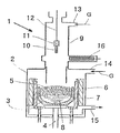
【図1】本発明の雰囲気ガス導入口を備えたシリコン単結晶引上げ機の構成例を示す概略図である。
【図2】従来の雰囲気ガス導入口を備えたシリコン単結晶引上げ機を示す概略図である。
【符号の説明】
1…シリコン単結晶引上げ機、2…主チャンバー、3…ルツボ、4…支持軸、5…原料シリコン多結晶、6…断熱材、7…黒鉛ヒータ、8…シリコン融液、
9…プルチャンバー、10…種結晶、11…種結晶保持具、12…ワイヤ、
13…プルチャンバーガス導入口、14…主チャンバーガス導入口、
15…ガス排気口、16…ゲートバルブ。
G…炉内雰囲気ガス。[0001]
BACKGROUND OF THE INVENTION
The present invention relates to a silicon single crystal manufacturing method and a pulling machine for growing a silicon single crystal rod by the Czochralski Method (CZ method).
[0002]
[Prior art]
In recent years, in the production of a silicon single crystal by the CZ method, the diameter is increased and the weight is increased. To increase the diameter and weight of crystals, it is essential to increase the size of the puller and increase the amount of raw materials supplied. At that time, the processing time in each process related to crystal growth tends to be long, and the improvement in productivity due to the increase in diameter and weight is not expected and it is a factor of cost increase. There's a problem.
[0003]
Among them, the process of melting a large amount of silicon polycrystal as a raw material requires a relatively long time, and the melting time is increased in direct proportion to the amount of raw material supplied to supply the raw material to the crucible. In the CZ method, an initial raw material is generally charged in a crucible and the raw material is melted by heating from a graphite heater around the crucible. Methods for shortening the raw material melting time include auxiliary heaters, lasers, and the like. A method of using another heat source in combination has been proposed.
[0004]
However, in the method of using another heating source in combination with these melting methods, there is a problem that the heating apparatus becomes complicated, heating energy increases, and equipment costs are increased, so that the cost cannot be reduced. It may also adversely affect manufacturing.
[0005]
[Problems to be solved by the invention]
Therefore, the present invention has been made in view of such conventional problems, and in a method for producing a silicon single crystal in which a single crystal rod is grown by the CZ method, when a raw material is melted, an ordinary puller is used. While maintaining the internal structure of the furnace, the atmospheric gas flow rate is suppressed to a small amount to suppress the heat radiation to the outside of the system, thereby increasing the amount of heat supplied to the raw material heating and shortening the raw material melting time, large diameter, high weight The main object of the present invention is to provide a silicon single crystal manufacturing method and a pulling machine that can improve the productivity and cost reduction of single crystal rods.
[0006]
[Means for Solving the Problems]
In order to solve the above-mentioned problems, the present invention provides a method for producing a silicon single crystal in which a single crystal rod is grown by the Czochralski method. When melting a raw material, a furnace atmosphere gas flow rate of a puller is 100 L / min or less. It is a manufacturing method of a silicon single crystal characterized by melting as follows.
[0007]
In this way, when melting silicon polycrystal as a raw material for a single crystal, the furnace atmosphere Ar gas flow rate of the puller is reduced to 100 L / min or less to contact the melting raw material surface in the quartz crucible. In addition, it is possible to reduce the amount of heat directly taken from the raw material by the Ar gas discharged from the lower part of the main chamber to the outside of the furnace. Therefore, out of the calorific value of the graphite heater, the amount of heat released to the outside of the system is reduced, which shortens the melting time of the silicon polycrystal, and can be adequately adapted to future increases in the diameter and weight of single crystal rods. And can significantly improve productivity and cost.
[0008]
The present invention relates to a method for producing a silicon single crystal in which a single crystal rod is grown by the Czochralski method. When melting the raw material, the furnace atmosphere gas flow rate (L / min) of the puller is set to a crucible diameter (mm). It is a method for producing a silicon single crystal characterized by melting at 0.23 times or less.
Thus, if melting is performed under the above conditions, the melting time can be shortened regardless of the diameter of the crucible and the amount of raw material.
[0009]
And in this case, among the pre-Symbol furnace atmosphere gas flow rate, the rate of direct contact with the raw material, it is possible to melt the raw material as a 10-50% of the total flow.
[0010]
In this way, the flow of the atmosphere Ar gas in the furnace is divided into at least two parts, for example, one is made to flow in direct contact with the raw material in the quartz crucible from the top of the pull chamber containing the single crystal pulled up from the melting crucible as usual, The ratio is reduced to an amount of 10 to 50% of the total flow rate. The other is introduced from the top of the main chamber and flows so as to reach the entire main chamber, and the ratio is 90 to 50% of the total flow rate to melt the raw material. By doing so, the amount of heat directly taken from the raw material by the gas can be reduced, so that the heat amount from the graphite heater can be efficiently used for melting the raw material, and the melting time can be shortened. In addition, even if the gas from the top of the pull chamber is reduced to 10% or more and 50% or less of the total flow rate than usual, SiO generated from the raw material melt hardly adheres to the inner wall of the pull chamber, There is almost no adverse effect when pulling up.
[0011]
Furthermore, in this case, the pressure of the furnace atmosphere gas at the time of melting the pre-Symbol raw material, it is preferably less than or equal to 60 hPa.
Thus, if the atmospheric pressure in the furnace is reduced to 60 hPa or less and forced exhaustion is performed, it is possible to avoid adverse effects even if the gas flow rate is reduced.
In other words, when the raw material silicon polycrystal is melted, the gas contained in the raw material itself or the quartz crucible becomes bubbles and dissolves in the melt. However, if melting is performed at a furnace pressure of 60 hPa or less during melting, the solubility of the gas in the melt is reduced and the buoyancy is increased, so that bubbles are likely to volatilize outside the melt, not only bubbles but also Na Volatilization of impurities such as these is also promoted. Accordingly, it is possible to prevent pinholes caused by bubbles in the crystal at the time of pulling, and to prevent dislocation of the crystal due to bubbles and impurities.
[0012]
Moreover, under the reduced pressure, the process of melting the polycrystalline block and the defoaming after the melt is changed to a direction in which the apparent thermal conductivity is increased, and the melting rate can be increased.
Furthermore, the SiO generated from the melt surface reacts with the graphite heater that is transported by Ar gas and glows red, and CO is generated, which tries to dissolve into the silicon melt. This also has a furnace pressure of 60 hPa or less. If forced evacuation is performed under reduced pressure, dissolution into the silicon melt and incorporation into the crystal are suppressed, and the carbon concentration defect rate due to CO in the crystal can be reduced.
[0013]
Next, in the silicon single crystal pulling machine for growing a single crystal rod by the Czochralski method, the present invention has a puller furnace atmosphere gas inlet installed at the top of the main chamber and the top of the pull chamber, In addition, the silicon single crystal pulling machine is characterized in that an exhaust port is provided in a lower portion of the main chamber.
[0014]
In this way, when the inlet of the atmospheric gas in the furnace is provided in at least two locations and the gas flow rate is divided and flowed at a desired ratio, for example, the gas flow rate that flows directly from the top of the pull chamber to the raw material surface being melted A silicon single crystal pulling machine that can reduce the amount of heat taken away from the raw material by the gas, effectively use the calorific value of the graphite heater for melting the raw material, and shorten the raw material melting time. Become.
[0015]
DETAILED DESCRIPTION OF THE INVENTION
Hereinafter, embodiments of the present invention will be described in detail, but the present invention is not limited thereto.
As described above, when the silicon single crystal is grown by the CZ method, the supply amount of the raw material silicon polycrystal increases as the diameter increases and the weight increases. It has become a factor of decrease and cost increase.
Therefore, as a result of studying the heat balance between the graphite heater and the atmosphere gas in the puller furnace or between the raw material silicon polycrystals in the raw material melting process, the present inventors have determined that the atmospheric gas flow rate and the flow thereof can be reduced. The present invention has been completed by finding out that the route has a great influence and filling in the conditions in detail.
[0016]
In melting the raw material in the silicon single crystal puller furnace, the raw material silicon polycrystal is melted using a graphite heater as a heating source. The calorific value of the graphite heater is transmitted to the raw material through the quartz crucible holding the raw material and the graphite crucible supporting it. Most of the heat transferred to the raw material is used to melt the raw material, but there is a part that escapes around the crucible without being used. Basically, it escapes into the furnace by radiation and heat conduction, but it becomes almost steady state except for forced cooling parts such as chamber walls, so there is no large heat transfer. it is conceivable that.
[0017]
Usually, however, the Ar gas in the furnace is introduced from the top of the pull chamber in the melting process of the raw material, descends in the pull chamber, contacts the raw material surface in the quartz crucible, and then enters the outside of the furnace from the lower part of the main chamber. Therefore, the amount of heat taken away from the raw material by this gas has a relatively large influence on the melting time and cannot be ignored.
[0018]
Therefore, the influence of the gas flow rate on the raw material melting time was investigated by changing the flow rate of the atmospheric Ar gas.
(Test 1)
A quartz crucible with a diameter of 450 mm is filled with a raw material of 60 kg of polycrystalline silicon, and a silicon single crystal with a diameter of 150 mm is pulled up. The heating power at the time of melting is 100 kW, the pressure in the furnace is 50 hPa, the total amount of Ar gas flow in the furnace It was set to 5 levels of 150, 120, 100, 80, and 50 L / min, and the melting time of the raw material was measured by flowing from the top of the pull chamber. The results are shown in Table 1 in terms of ratios when the melting time is 1 when the flow rate of the atmospheric Ar gas is 100 L / min.
[0019]
[Table 1]
From Table 1, it was found that the melting time becomes longer when it exceeds 100 L / min. Thus, if the atmosphere Ar gas flow rate is reduced, the amount of heat directly taken from the raw material can be reduced, and the calorific value of the graphite heater can be efficiently used for melting the raw material, thereby shortening the melting time. be able to.
[0021]
(Test 2)
Next, as an attempt to further increase the melting time shortening effect by reducing the amount of gas, the furnace atmosphere Ar gas flow rate was divided into two, and the conventional flow channel directly contacting the raw material from the top of the pull chamber and the top of the main chamber The flow path from was provided, and the influence on the melting time was investigated by changing the division ratio (see FIG. 1). The investigation conditions were the same as those in
[0022]
[Table 2]
As can be seen from Table 2, the melting time is shortened as the Ar gas flow rate from the top of the pull chamber is reduced, that is, as the Ar gas flow rate from the top of the main chamber is increased.
From this result, in the melting process of the raw material, if the ratio of direct contact with the raw material of the atmosphere Ar gas flow rate in the furnace is 10% to 50% of the entire flow rate, the melting time is shortened by 10% or more. I found that I can do it.
[0024]
Usually, during melting of the raw material, 100% of the atmosphere gas in the furnace flows from the top of the pull chamber to create an inert atmosphere, maintaining the pressure in the furnace, and impurity gases such as SiO and Na generated from the raw material polycrystal during melting. Draining from the bottom of the main chamber.
On the other hand, in the present invention, during the raw material melting, the flow of gas that does not directly hit the raw material, that is, the flow from the top of the main chamber is the main, and the amount of 90 to 50% of the total amount flows. On the other hand, the gas in direct contact with the raw material was 10 to 50% of the total amount, introduced from the top of the pull chamber, and lowered toward the opening of the crucible. In this way, the amount of heat directly taken from the raw material by the gas can be reduced, so that the cooling of the raw material is prevented, the calorific value of the graphite heater is used efficiently for melting the raw material, and the melting time is shortened. Became possible. Further, since 10% of the gas flow rate from the top of the pull chamber is secured, SiO generated from the raw material hardly adheres to the inner wall of the pull chamber and does not adversely affect the pulling.
[0025]
(Test 3)
Furthermore, the effect of furnace pressure was investigated. The furnace pressure when melting the raw material polycrystalline silicon is set at three levels of 10 , 50, and 100 hPa, the furnace atmosphere Ar gas flow rate is 100 L / min, and the split ratio between the pull chamber and the main chamber is 50% and 50%. Measured the melting time under the same conditions as in
[0026]
[Table 3]
As is clear from Table 3, the melting time tended to be somewhat shorter at low pressure. As for the quality of the single crystal, if the furnace pressure is 60 hPa or less, the generation of pinholes in the single crystal can be suppressed and the carbon concentration can be lowered.
[0028]
Thus, it has been found that when the raw material is melted, it is preferable that the pressure in the furnace atmosphere gas be 60 hPa or less.
In general, when the raw material polycrystal is melted, the gas contained in the raw material itself or the quartz crucible becomes bubbles and dissolves in the melt. However, if melting is performed under a reduced pressure of, for example, 60 hPa or less during melting, the solubility of the gas in the melt is reduced and the buoyancy is increased, so that bubbles easily volatilize outside the melt, not only bubbles, Volatilization of impurities such as Na is also promoted. Accordingly, it is possible to prevent pinholes caused by bubbles in the crystal at the time of pulling, and to prevent dislocation of the crystal due to bubbles and impurities.
[0029]
Moreover, under the reduced pressure, the process of melting the polycrystal lump or defoaming after becoming a melt changes in the direction of increasing the thermal conductivity, and the melting rate can be increased.
Furthermore, SiO generated from the melt surface reacts with a graphite heater which is transported by Ar gas and glows red, and CO is generated to try to dissolve into the silicon melt, which also has a furnace pressure of 60 hPa. If forced evacuation is performed as the following decompression, the dissolution into the silicon melt and the incorporation into the crystal are suppressed, and the carbon concentration defect rate due to CO in the crystal can be reduced.
[0030]
(Test 4)
Next, the crucible diameter is set to 600 mm (24 inches), the raw material is filled with 130 kg of polycrystalline silicon, the silicon single crystal having a diameter of 200 mm is pulled up, the heating power at the time of melting is 150 kW, and the furnace atmosphere Ar gas flow rate The effect of increasing the size of the puller was investigated. The total amount of Ar gas flow in the furnace at the time of melting the raw material polycrystalline silicon was set at three levels of 100, 140, and 180 L / min, and the melting time was compared by flowing Ar gas from the top of the pull chamber under the same conditions as in
[0031]
[Table 4]
As is apparent from Table 4, the amount of power required for melting per unit weight of the raw material is proportional to the crucible diameter when the crucible diameter of test 1c is 450 mm (18 inches) and the total flow rate is 100 L / min. In Test 4b in which the total amount of Ar gas flow was 140 L / min, the melting efficiency was almost the same. Furthermore, in the test 4a in which the amount of Ar was reduced to 100 L / min, the melting efficiency was slightly improved. On the other hand, in the test 4c increased to 180 L / min, the melting efficiency decreased.
When the crucible diameter is 600 mm, if the Ar gas flow rate is 140 L / min or less, which is 0.23 times the crucible diameter, the melting can be efficiently performed in the same manner as the gas flow rate of 100 L / min or less when the crucible diameter is 450 mm. it can.
Thus, by setting the Ar gas flow rate to 0.23 times or less of the crucible diameter, the melting time can be shortened regardless of the diameter of the crucible and the amount of raw material.
[0033]
Hereinafter, the method and the puller of the present invention will be specifically described with reference to the drawings.
First, an example of the configuration of a silicon single crystal puller using the CZ method used in the present invention will be described with reference to FIG.
As shown in FIG. 1, a
[0034]
There is an opening in the center of the ceiling of the
[0035]
During this time, when the
Further, the gas introduction amount of the pull chamber and the gas introduction amount of the main chamber can be independently controlled, and the ratio can be freely adjusted.
[0036]
For comparison with the silicon single crystal puller of the present invention, a conventional puller is shown in FIG.
The basic structure is the same as that of the pulling machine of the present invention, but the furnace atmosphere gas inlet is not equipped with the main chamber gas inlet, but only with the pull
[0037]
In addition, this invention is not limited to the said embodiment. The above-described embodiment is an exemplification, and the present invention has substantially the same configuration as the technical idea described in the claims of the present invention, and any device that exhibits the same function and effect is the present invention. It is included in the technical scope of the invention.
[0038]
For example, in the embodiment of the present invention, a silicon single crystal rod having a diameter of 150 mm (6 inches) is grown. However, in the recent increase in diameter of 200 mm (8 inches) to 400 mm (16 inches) or more. It can respond enough. In the present invention, in principle, any diameter, length, and weight of a single crystal rod or crucible diameter, and pulling with a raw material filling amount can naturally be applied.
Needless to say, the present invention can also be applied to a so-called MCZ method in which a horizontal magnetic field, a vertical magnetic field, a cusp magnetic field, or the like is applied to a silicon melt.
[0039]
【The invention's effect】
As described above, according to the present invention, the amount of heat taken from the source polycrystal can be reduced by reducing the flow rate of the atmospheric gas in the furnace that directly hits the surface of the source silicon polycrystal in the quartz crucible, Since the calorific value of the graphite heater can be efficiently used for melting the raw material, efficient melting is possible and the melting time can be greatly shortened. Accordingly, it is possible to sufficiently adapt to future increases in the diameter, length, and weight of single crystal rods, and productivity, yield, and cost can be significantly improved.
[Brief description of the drawings]
FIG. 1 is a schematic view showing a configuration example of a silicon single crystal puller equipped with an atmospheric gas inlet of the present invention.
FIG. 2 is a schematic view showing a silicon single crystal pulling machine equipped with a conventional atmosphere gas inlet.
[Explanation of symbols]
DESCRIPTION OF
9 ... Pull chamber, 10 ... Seed crystal, 11 ... Seed crystal holder, 12 ... Wire,
13 ... Pull chamber gas inlet, 14 ... Main chamber gas inlet,
15 ... gas exhaust port, 16 ... gate valve.
G: Furnace atmosphere gas.
Claims (3)
Priority Applications (1)
| Application Number | Priority Date | Filing Date | Title |
|---|---|---|---|
| JP33437598A JP3832536B2 (en) | 1998-11-25 | 1998-11-25 | Method for producing silicon single crystal and pulling machine |
Applications Claiming Priority (1)
| Application Number | Priority Date | Filing Date | Title |
|---|---|---|---|
| JP33437598A JP3832536B2 (en) | 1998-11-25 | 1998-11-25 | Method for producing silicon single crystal and pulling machine |
Publications (2)
| Publication Number | Publication Date |
|---|---|
| JP2000159596A JP2000159596A (en) | 2000-06-13 |
| JP3832536B2 true JP3832536B2 (en) | 2006-10-11 |
Family
ID=18276675
Family Applications (1)
| Application Number | Title | Priority Date | Filing Date |
|---|---|---|---|
| JP33437598A Expired - Fee Related JP3832536B2 (en) | 1998-11-25 | 1998-11-25 | Method for producing silicon single crystal and pulling machine |
Country Status (1)
| Country | Link |
|---|---|
| JP (1) | JP3832536B2 (en) |
Families Citing this family (10)
| Publication number | Priority date | Publication date | Assignee | Title |
|---|---|---|---|---|
| JP3360626B2 (en) | 1998-12-01 | 2002-12-24 | 三菱住友シリコン株式会社 | Method for producing silicon single crystal |
| JP5266616B2 (en) * | 2006-02-07 | 2013-08-21 | 信越半導体株式会社 | Method for producing silicon single crystal ingot |
| JP4716331B2 (en) * | 2006-09-29 | 2011-07-06 | コバレントマテリアル株式会社 | Single crystal manufacturing method |
| JP4862836B2 (en) * | 2008-02-05 | 2012-01-25 | 信越半導体株式会社 | Single crystal manufacturing apparatus and single crystal manufacturing method |
| JP6413970B2 (en) * | 2015-07-29 | 2018-10-31 | 信越半導体株式会社 | Method for growing silicon single crystal |
| JP6090391B2 (en) | 2015-08-21 | 2017-03-08 | 株式会社Sumco | Method for producing silicon single crystal |
| WO2017069112A1 (en) * | 2015-10-23 | 2017-04-27 | 株式会社トクヤマ | Silicon single crystal ingot pull-up device and silicon single crystal ingot production method |
| DE102019208670A1 (en) * | 2019-06-14 | 2020-12-17 | Siltronic Ag | Process for the production of semiconductor wafers from silicon |
| KR102601625B1 (en) * | 2019-07-05 | 2023-11-10 | 주식회사 엘지화학 | Manufacturing methode for siliconcarbide single crystal |
| KR102492237B1 (en) * | 2020-11-25 | 2023-01-26 | 에스케이실트론 주식회사 | Method and apparatus for growing silicon single crystal ingot |
-
1998
- 1998-11-25 JP JP33437598A patent/JP3832536B2/en not_active Expired - Fee Related
Also Published As
| Publication number | Publication date |
|---|---|
| JP2000159596A (en) | 2000-06-13 |
Similar Documents
| Publication | Publication Date | Title |
|---|---|---|
| US20190136407A1 (en) | Single crystal ingots with reduced dislocation defects and methods for producing such ingots | |
| US10544517B2 (en) | Growth of a uniformly doped silicon ingot by doping only the initial charge | |
| US6553787B1 (en) | Method for manufacturing quartz glass crucible | |
| JP3832536B2 (en) | Method for producing silicon single crystal and pulling machine | |
| JPH059097A (en) | Method for pulling up silicon single crystal | |
| JP2005336020A (en) | Silicon single crystal puller and method of manufacturing silicon single crystal | |
| CN114959880B (en) | A quartz crucible, crucible assembly and crystal pulling furnace for producing single crystal silicon rods | |
| JP4810346B2 (en) | Method for producing sapphire single crystal | |
| US20060191468A1 (en) | Process for producing single crystal | |
| CN213652724U (en) | Thermal field structure of continuous crystal pulling single crystal furnace | |
| EP0675214A1 (en) | Method of growing crystals | |
| CN101175872B (en) | Growth method of silicon single crystal | |
| CN114855263A (en) | A kind of crystal growth method and growth device | |
| US5840120A (en) | Apparatus for controlling nucleation of oxygen precipitates in silicon crystals | |
| US7628854B2 (en) | Process for producing silicon single crystal | |
| JPH07118089A (en) | Recharging device and recharging method for polycrystal | |
| JP2710433B2 (en) | Single crystal pulling device | |
| KR100835293B1 (en) | Method of manufacturing silicon single crystal ingot | |
| JP3900816B2 (en) | Silicon wafer manufacturing method | |
| US7442251B2 (en) | Method for producing silicon single crystals and silicon single crystal produced thereby | |
| JPH05238874A (en) | Production apparatus for silicon single crystal | |
| JP2020045258A (en) | Method for producing silicon single crystal | |
| JP2747626B2 (en) | Single crystal manufacturing equipment | |
| JPH06340493A (en) | Apparatus for growing single crystal and growing method | |
| JP2005200279A (en) | Method for manufacturing silicon ingot, solar cell |
Legal Events
| Date | Code | Title | Description |
|---|---|---|---|
| A977 | Report on retrieval |
Free format text: JAPANESE INTERMEDIATE CODE: A971007 Effective date: 20060216 |
|
| A131 | Notification of reasons for refusal |
Free format text: JAPANESE INTERMEDIATE CODE: A131 Effective date: 20060307 |
|
| A521 | Written amendment |
Free format text: JAPANESE INTERMEDIATE CODE: A523 Effective date: 20060426 |
|
| TRDD | Decision of grant or rejection written | ||
| A01 | Written decision to grant a patent or to grant a registration (utility model) |
Free format text: JAPANESE INTERMEDIATE CODE: A01 Effective date: 20060628 |
|
| A61 | First payment of annual fees (during grant procedure) |
Free format text: JAPANESE INTERMEDIATE CODE: A61 Effective date: 20060711 |
|
| R150 | Certificate of patent or registration of utility model |
Free format text: JAPANESE INTERMEDIATE CODE: R150 |
|
| FPAY | Renewal fee payment (event date is renewal date of database) |
Free format text: PAYMENT UNTIL: 20090728 Year of fee payment: 3 |
|
| S531 | Written request for registration of change of domicile |
Free format text: JAPANESE INTERMEDIATE CODE: R313531 |
|
| FPAY | Renewal fee payment (event date is renewal date of database) |
Free format text: PAYMENT UNTIL: 20090728 Year of fee payment: 3 |
|
| R350 | Written notification of registration of transfer |
Free format text: JAPANESE INTERMEDIATE CODE: R350 |
|
| FPAY | Renewal fee payment (event date is renewal date of database) |
Free format text: PAYMENT UNTIL: 20090728 Year of fee payment: 3 |
|
| FPAY | Renewal fee payment (event date is renewal date of database) |
Free format text: PAYMENT UNTIL: 20100728 Year of fee payment: 4 |
|
| FPAY | Renewal fee payment (event date is renewal date of database) |
Free format text: PAYMENT UNTIL: 20110728 Year of fee payment: 5 |
|
| FPAY | Renewal fee payment (event date is renewal date of database) |
Free format text: PAYMENT UNTIL: 20110728 Year of fee payment: 5 |
|
| FPAY | Renewal fee payment (event date is renewal date of database) |
Free format text: PAYMENT UNTIL: 20120728 Year of fee payment: 6 |
|
| FPAY | Renewal fee payment (event date is renewal date of database) |
Free format text: PAYMENT UNTIL: 20120728 Year of fee payment: 6 |
|
| FPAY | Renewal fee payment (event date is renewal date of database) |
Free format text: PAYMENT UNTIL: 20130728 Year of fee payment: 7 |
|
| R250 | Receipt of annual fees |
Free format text: JAPANESE INTERMEDIATE CODE: R250 |
|
| R250 | Receipt of annual fees |
Free format text: JAPANESE INTERMEDIATE CODE: R250 |
|
| R250 | Receipt of annual fees |
Free format text: JAPANESE INTERMEDIATE CODE: R250 |
|
| S531 | Written request for registration of change of domicile |
Free format text: JAPANESE INTERMEDIATE CODE: R313531 |
|
| R350 | Written notification of registration of transfer |
Free format text: JAPANESE INTERMEDIATE CODE: R350 |
|
| R250 | Receipt of annual fees |
Free format text: JAPANESE INTERMEDIATE CODE: R250 |
|
| R250 | Receipt of annual fees |
Free format text: JAPANESE INTERMEDIATE CODE: R250 |
|
| LAPS | Cancellation because of no payment of annual fees |