JP3832571B2 - Roll baler - Google Patents
Roll baler Download PDFInfo
- Publication number
- JP3832571B2 JP3832571B2 JP2001307662A JP2001307662A JP3832571B2 JP 3832571 B2 JP3832571 B2 JP 3832571B2 JP 2001307662 A JP2001307662 A JP 2001307662A JP 2001307662 A JP2001307662 A JP 2001307662A JP 3832571 B2 JP3832571 B2 JP 3832571B2
- Authority
- JP
- Japan
- Prior art keywords
- conveyor
- bale
- collected material
- collected
- string case
- Prior art date
- Legal status (The legal status is an assumption and is not a legal conclusion. Google has not performed a legal analysis and makes no representation as to the accuracy of the status listed.)
- Expired - Fee Related
Links
- 239000000463 material Substances 0.000 claims description 31
- 238000000465 moulding Methods 0.000 claims description 13
- 238000000748 compression moulding Methods 0.000 claims 1
- 229920000136 polysorbate Polymers 0.000 description 6
- 244000025254 Cannabis sativa Species 0.000 description 2
- 238000002360 preparation method Methods 0.000 description 2
- 238000009412 basement excavation Methods 0.000 description 1
- 238000004140 cleaning Methods 0.000 description 1
- 238000012856 packing Methods 0.000 description 1
- 238000005096 rolling process Methods 0.000 description 1
- 239000004071 soot Substances 0.000 description 1
- 239000010902 straw Substances 0.000 description 1
- 230000037303 wrinkles Effects 0.000 description 1
Images


Landscapes
- Basic Packing Technique (AREA)
Description
【0001】
【発明の属する技術分野】
本発明は、刈り取られて放置される牧草、排藁等の収集物を収集して、ロール状のベールに梱包するロールベーラに関するものである。
【0002】
【従来の技術】
このようなロールベーラは、実開平2−70640号公報に記載されているように、ピックアップ装置から搬送コンベアを介して、ベール成形室に地上散在物を取り込んで、束ねコンベアでロール状のベールを成形するようにしている。
【0003】
【発明が解決しようとする課題】
このようなロールベーラでは、収集物を多量に取り込む場合に備えて、収集物取入口をある程度広げる必要があり、切藁のような短く分離しやすい収集物の場合は、搬送コンベアで搬送されてベール室内に取り込まれても、束ねコンベアで回転させられているうちに収集物取込口からわき出して、この収集物取込口の前方に多く停滞し、結束時に収集物取込口からベール成形室内へトワインを供給する際、停滞した収集物が障害となってベール成形室内部へ入り込むのを妨げられることがあった。
また、長藁を取り込む場合にも、束ねコンベアの前端折り返し部に引かれて、ベール室からの藁のつれ出しが発生し、束ねコンベア上部へ藁が詰まってしまい、この詰まった藁を取り除くのに時間がかかってしまうという問題があった。
本発明は、収集物が収集物取込口の前方および上方に多く停滞したことを作業者に早く知らせると共に、詰まった藁を容易に取り除くことのできるロールベーラを提供することを課題とする。
【0004】
【課題を解決するための手段】
機体前下方に設けたピックアップ装置5と、収集物をベールに圧縮成形する束ねコンベア4を備えるベール成形室6との間に搬送コンベア7を設け、該搬送コンベア7と束ねコンベア4の前端の折返部との間に形成する収集物取込口9の上方より結束用トワイン19をベール成形室6内へ供給して結束するロールベーラにおいて、束ねコンベア4前端の折返部2の上方空間部Aに機体上面3に取着されるひもケース1を収納すると共に、その取付部前端または後端を支点に他端を上方へ回動可能に構成し、前記折返部2付近の上方空間部Aにおける収集物の停滞時、その押圧力でひもケース1を上方へ退避回動可能に構成する。
【0005】
【発明の作用及び効果】
ピックアップ装置5で地上から拾い上げられた収集物は、搬送コンベア7上に載せて搬送物押圧部材8で押さえられながらベール成形室6内へ送り込まれ、束ねコンベア4で回転させられながら、ベールに圧縮成形されるのであるが、束ねコンベア4の前端には、折り返し部2があるため、収集物が上方空間部Aに巻き上げられて停滞する場合がある。少量停滞することは、トワインの供給に対しての影響は少ないが、多量に停滞する場合には、早目に詰まりを取り除くことが必要となる。本発明では、空間部Aに停滞した収集物が、その押圧力でひもケース1を押し上げて、収集物が停滞していることを作業者へ早く知らせることが可能である。
また、収集物が停滞している場所にあるひもケース1が、上方へ開放されるので、その部分の掃除を簡単に行うことができる。トワインの供給に支障になるような多量の収集物が停滞した時には、ひもケース1が開放されて、掃除時期の基準にもなる。
【0006】
【発明の実施の形態】
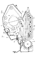
本発明の実施例を図面に基づいて説明する。図1に示すようにクローラ11からなる走行装置12を装備した走行機台13の前下方に設けたピックアップ装置6に続けて、搬送コンベア7を設ける。走行機台13上に搭載した固定機枠14と可動機枠14aの内部に、搬送コンベア7の後方部分と束ねコンベア4からなる円筒状のベール成形室6を設ける。
搬送コンベア7の上方には、固定機枠14の左右に横架した支軸15に、搬送コンベア7の前部から収集物取込口9に至る搬送物押圧部材8を設けて、収集物を搬送コンベア7に向けて押圧作用させるよう構成している。
固定機枠14の前部で搬送コンベア7の上方にはトワイン供給装置16を設け、ベール成形室6内でロール状のベールが圧縮成形されると、トワイン19を収集物取込口9から内部へ供給して、ベール成形室6でロール状に圧縮されたベールにトワイン19を左右全幅にわたって巻き付け梱包するようにしている。
固定機枠14の後下部には、ベール成形室6から転がり出るベールを、走行装置12の後部へ案内する案内板17を設けている。走行機台13上には、固定機枠14と可動機枠14aとの側部に原動機を搭載した原動機枠(図示省略)を設けている。
【0007】
次に上述のように構成されたロールベーラの作業態様について説明する。原動機によって走行装置12、搬送コンベア7、束ねコンベア4及びピックアップ装置5を駆動させると、ピックアップ装置5がワラ草や牧草などの収集物を拾い上げ、搬送コンベア7に移載する。搬送コンベア7に移載された収集物は、搬送物押圧部材8によって押圧されながら収集物取込口9からベール成形室6内に供給される。ベール成形室6に供給された収集物は、搬送コンベア4の後方部分及び束ねコンベア4によってロール状態に束ねられた後、トワイン供給装置16から引き出されたトワイン19が収集物取込口9からベール成形室6内へ供給され、ベール外周に巻きつけられて結束される。結束が終了すれば、可動機枠14aを上方へ回動してベール成形室6を開放し、ベールを機外へ転がり出させる。
【0008】
このようなロールベーラでは、収集物を多量に取り込む場合に備えて、ベール成形室6の入口である収集物取込口9を、ある程度広げておく必要があるが、ベール成形室6を形成して、収集物を回転させながらロール状のベールを成形する束ねコンベア4の両端には、コンベアの折り返し部分があり、特に、収集物取込口9の上方に位置する束ねコンベア4前端折り返し部2においては、収集物取込口9からわき出した収集物が該折り返し部2で巻き上げられて、上方空間部Aに停滞してしまうことがある。この部分の収集物停滞は、ベールを成形することに対しての影響は少ないが、トワイン19供給時には支障となる。
【0009】
束ねコンベア4前端の折返部2の上方空間部Aには、ひもケース1を備え、図2に示すようにひもケース1は、機体上面3から大部分を内方へ収納した形状で左右方向に横架させて設け、ひもケース1内にはベールを梱包するためのトワイン19が納められている。ひもケース1の上側には、機体上面3に蝶板21で回動自在に取付けられた蓋20を設ける。
ひもケース1の前側の機体上面3付近には、支点軸18を設け、ひもケース1は、支点軸18を支点として上方へ回動し、ひもケース1の後端が蓋20を持ち上げるよう構成されている。蓋20は、トワイン19の補充や交換時に開放可能とし、ひもケース1の下側へ収集物が停滞した時、その押圧力でひもケース1が上方へ蓋20と共に開放して、収集物の停滞を早目に作業者へ知らせることができる。なお、前記蓋20は、ひもケース1へ回動自在に設けても良く、また、機体上面3に固定し、機体上面3自体が一体的に回動するよう構成しても良い。すなわち、ひもケース1が停滞した収集物の押圧力で上方へ回動すると共に、持ち上げられて移動するカバーであれば良い。
図3は、ひもケース1の取外しについて記載したもので、支点軸18は、ひもケース1のコの字形状をした回動部材22に嵌め込まれており蓋20を開放させた後、ひもケース1を支点軸18を支点に矢印B方向へ回動させると、ひもケース1全体が取外し可能になる構成である。
【0010】
以上の構成により束ねコンベア4の前端折返部2の上方空間部Aへ収集物が停滞した時、その押圧力でひもケース1が押し上げられて、収集物の停滞を作業者へ知らせることができると共に、停滞場所が開放されるため、収集物を取除くことが簡単に行える。なお、ひもケース1の回動の支点軸18については、前記ひもケース1の前端ではなく後端でも同様の効果がある。
【図面の簡単な説明】
【図1】本発明実施例の全体側断面図。
【図2】本発明の実施例を示す部分拡大側断面図。
【図3】本発明の実施例を示す部分拡大側断面図。
【符号の説明】
1 ひもケース
2 折り返し部
3 機体上面
4 束ねコンベア
5 ピックアップ装置
6 ベール成形室
7 搬送コンベア
8 搬送物押圧部材
9 収集物取込口
19 トワイン[0001]
BACKGROUND OF THE INVENTION
The present invention relates to a roll baler which collects collected materials such as grass and excavation which are cut and left and packed in a roll-shaped bale.
[0002]
[Prior art]
As described in Japanese Utility Model Laid-Open No. 2-70640, such a roll baler takes in the ground scattered material from the pick-up device via the conveyor and forms the bale in a bundling conveyor. Like to do.
[0003]
[Problems to be solved by the invention]
In such a roll baler, it is necessary to widen the intake of collected material to some extent in preparation for collecting a large amount of collected material. Even if it is taken into the room, it is pulled out from the collection inlet while being rotated by the bundling conveyor, and it stays a lot in front of this collection inlet and bales from the collection inlet at the time of binding. When the twain is supplied into the room, the stagnation of the collected material may become an obstacle and prevent entry into the bale molding room.
In addition, even when taking a long sheet, it will be pulled to the folding end of the front end of the bundling conveyor, causing the hail to come out of the bale chamber, clogging the upper part of the bundling conveyor, and removing this clogged wrinkle. There was a problem that it took time.
An object of the present invention is to provide a roll baler that can quickly notify the operator that a large amount of collected material has stagnated in front and above the collected material intake and can easily remove clogged soot.
[0004]
[Means for Solving the Problems]
A conveying conveyor 7 is provided between the pickup device 5 provided in the lower front of the machine body and a
[0005]
[Action and effect of the invention]
The collected material picked up from the ground by the pick-up device 5 is placed on the transport conveyor 7 and sent to the
Moreover, since the string case 1 in the place where the collection is stagnant is opened upward, the portion can be easily cleaned. When a large amount of collected material that hinders the supply of Twain is stagnant, the string case 1 is opened, which also serves as a reference for cleaning time.
[0006]
DETAILED DESCRIPTION OF THE INVENTION
Embodiments of the present invention will be described with reference to the drawings. As shown in FIG. 1, a conveyor 7 is provided following the
Above the transport conveyor 7, a transport material pressing member 8 extending from the front portion of the transport conveyor 7 to the collected
A
A
[0007]
Next, the working mode of the roll baler configured as described above will be described. When the
[0008]
In such a roll baler, it is necessary to widen the
[0009]
The upper space A of the folded portion 2 at the front end of the bundling conveyor 4 is provided with a string case 1, and the string case 1 has a shape in which most of the string case 1 is stored inward from the
A
FIG. 3 shows the removal of the string case 1, and the
[0010]
With the above configuration, when the collected material stagnates in the upper space A of the front end folding portion 2 of the bundle conveyor 4, the string case 1 is pushed up by the pressing force, and the operator can be notified of the stagnation of the collected material. Because the stagnation area is opened, it is easy to remove the collected material. Note that the
[Brief description of the drawings]
FIG. 1 is an overall side sectional view of an embodiment of the present invention.
FIG. 2 is a partially enlarged side sectional view showing an embodiment of the present invention.
FIG. 3 is a partially enlarged side sectional view showing an embodiment of the present invention.
[Explanation of symbols]
DESCRIPTION OF SYMBOLS 1 String case 2
Claims (1)
Priority Applications (1)
| Application Number | Priority Date | Filing Date | Title |
|---|---|---|---|
| JP2001307662A JP3832571B2 (en) | 2001-10-03 | 2001-10-03 | Roll baler |
Applications Claiming Priority (1)
| Application Number | Priority Date | Filing Date | Title |
|---|---|---|---|
| JP2001307662A JP3832571B2 (en) | 2001-10-03 | 2001-10-03 | Roll baler |
Publications (2)
| Publication Number | Publication Date |
|---|---|
| JP2003111514A JP2003111514A (en) | 2003-04-15 |
| JP3832571B2 true JP3832571B2 (en) | 2006-10-11 |
Family
ID=19127093
Family Applications (1)
| Application Number | Title | Priority Date | Filing Date |
|---|---|---|---|
| JP2001307662A Expired - Fee Related JP3832571B2 (en) | 2001-10-03 | 2001-10-03 | Roll baler |
Country Status (1)
| Country | Link |
|---|---|
| JP (1) | JP3832571B2 (en) |
Families Citing this family (1)
| Publication number | Priority date | Publication date | Assignee | Title |
|---|---|---|---|---|
| BE1018763A3 (en) * | 2009-05-27 | 2011-08-02 | Cnh Belgium Nv | A METHOD FOR CONTROLLING A WIRE BRAKE DEVICE OF A RECTANGULAR BALL PRESS. |
-
2001
- 2001-10-03 JP JP2001307662A patent/JP3832571B2/en not_active Expired - Fee Related
Also Published As
| Publication number | Publication date |
|---|---|
| JP2003111514A (en) | 2003-04-15 |
Similar Documents
| Publication | Publication Date | Title |
|---|---|---|
| JPH01132314A (en) | Method for cylindrically bundling harvested crop | |
| CA2989758A1 (en) | Agricultural baler with feeder duct wall attached to conveying channel wall | |
| TR201816317T4 (en) | Winding system and method for large cotton or biomass bales. | |
| KR101019749B1 (en) | Bale packing machine | |
| CN113728815A (en) | Traction storage type round bundle bundling machine and bundling method thereof | |
| CN109964563A (en) | Used plastic collection baling press | |
| US11363759B2 (en) | Guide means, baler and method | |
| US10888048B2 (en) | Material wrap system with self cleaning feature | |
| JP4001193B2 (en) | Roll baler | |
| JP2003111514A (en) | Roll baler | |
| JPH026753Y2 (en) | ||
| CN103843529A (en) | Integrated automatic-stripping cotton harvester used for harvesting, cleaning and adjusting cotton | |
| EP3289855B1 (en) | Spread roll cap system | |
| US20160000011A1 (en) | Plunger slot cover assembly for an agricultural baler | |
| JP4263041B2 (en) | Roll baler | |
| JPH06933Y2 (en) | Roll baler twain supply device | |
| JP2530185Y2 (en) | Roll baler | |
| JP2001309723A (en) | Roll baler | |
| JPS6112205Y2 (en) | ||
| JPH0333237Y2 (en) | ||
| JP4116460B2 (en) | Roll baler stalk recovery equipment | |
| JPS58149613A (en) | String applying apparatus of roll baler | |
| JPH0445486Y2 (en) | ||
| US2731783A (en) | hauswirth | |
| CN216650569U (en) | Bundling device for biomass straw collection |
Legal Events
| Date | Code | Title | Description |
|---|---|---|---|
| A621 | Written request for application examination |
Free format text: JAPANESE INTERMEDIATE CODE: A621 Effective date: 20040825 |
|
| A977 | Report on retrieval |
Free format text: JAPANESE INTERMEDIATE CODE: A971007 Effective date: 20060622 |
|
| TRDD | Decision of grant or rejection written | ||
| A01 | Written decision to grant a patent or to grant a registration (utility model) |
Free format text: JAPANESE INTERMEDIATE CODE: A01 Effective date: 20060628 |
|
| A61 | First payment of annual fees (during grant procedure) |
Free format text: JAPANESE INTERMEDIATE CODE: A61 Effective date: 20060711 |
|
| R150 | Certificate of patent or registration of utility model |
Free format text: JAPANESE INTERMEDIATE CODE: R150 |
|
| LAPS | Cancellation because of no payment of annual fees |