JP3836725B2 - Construction machine management system and construction machine - Google Patents
Construction machine management system and construction machine Download PDFInfo
- Publication number
- JP3836725B2 JP3836725B2 JP2001570922A JP2001570922A JP3836725B2 JP 3836725 B2 JP3836725 B2 JP 3836725B2 JP 2001570922 A JP2001570922 A JP 2001570922A JP 2001570922 A JP2001570922 A JP 2001570922A JP 3836725 B2 JP3836725 B2 JP 3836725B2
- Authority
- JP
- Japan
- Prior art keywords
- construction machine
- information
- position information
- failure
- base station
- Prior art date
- Legal status (The legal status is an assumption and is not a legal conclusion. Google has not performed a legal analysis and makes no representation as to the accuracy of the status listed.)
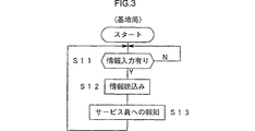
- Expired - Lifetime
Links
- 238000010276 construction Methods 0.000 title claims description 50
- 230000005540 biological transmission Effects 0.000 claims description 30
- 238000001514 detection method Methods 0.000 claims description 13
- 230000004044 response Effects 0.000 claims description 6
- 230000008520 organization Effects 0.000 claims 1
- 238000000034 method Methods 0.000 description 20
- 230000005856 abnormality Effects 0.000 description 16
- 238000004891 communication Methods 0.000 description 8
- 230000002159 abnormal effect Effects 0.000 description 4
- 238000010586 diagram Methods 0.000 description 4
- 239000000446 fuel Substances 0.000 description 3
- 230000003111 delayed effect Effects 0.000 description 2
- 238000012790 confirmation Methods 0.000 description 1
- 239000000498 cooling water Substances 0.000 description 1
- 230000001934 delay Effects 0.000 description 1
- 230000000694 effects Effects 0.000 description 1
- 230000003340 mental effect Effects 0.000 description 1
- 239000010705 motor oil Substances 0.000 description 1
Images








Classifications
-
- E—FIXED CONSTRUCTIONS
- E02—HYDRAULIC ENGINEERING; FOUNDATIONS; SOIL SHIFTING
- E02F—DREDGING; SOIL-SHIFTING
- E02F9/00—Component parts of dredgers or soil-shifting machines, not restricted to one of the kinds covered by groups E02F3/00 - E02F7/00
- E02F9/20—Drives; Control devices
-
- G—PHYSICS
- G08—SIGNALLING
- G08G—TRAFFIC CONTROL SYSTEMS
- G08G1/00—Traffic control systems for road vehicles
- G08G1/20—Monitoring the location of vehicles belonging to a group, e.g. fleet of vehicles, countable or determined number of vehicles
-
- E—FIXED CONSTRUCTIONS
- E02—HYDRAULIC ENGINEERING; FOUNDATIONS; SOIL SHIFTING
- E02F—DREDGING; SOIL-SHIFTING
- E02F9/00—Component parts of dredgers or soil-shifting machines, not restricted to one of the kinds covered by groups E02F3/00 - E02F7/00
- E02F9/20—Drives; Control devices
- E02F9/2025—Particular purposes of control systems not otherwise provided for
- E02F9/2045—Guiding machines along a predetermined path
-
- E—FIXED CONSTRUCTIONS
- E02—HYDRAULIC ENGINEERING; FOUNDATIONS; SOIL SHIFTING
- E02F—DREDGING; SOIL-SHIFTING
- E02F9/00—Component parts of dredgers or soil-shifting machines, not restricted to one of the kinds covered by groups E02F3/00 - E02F7/00
- E02F9/26—Indicating devices
-
- E—FIXED CONSTRUCTIONS
- E02—HYDRAULIC ENGINEERING; FOUNDATIONS; SOIL SHIFTING
- E02F—DREDGING; SOIL-SHIFTING
- E02F9/00—Component parts of dredgers or soil-shifting machines, not restricted to one of the kinds covered by groups E02F3/00 - E02F7/00
- E02F9/26—Indicating devices
- E02F9/267—Diagnosing or detecting failure of vehicles
Landscapes
- Engineering & Computer Science (AREA)
- Mining & Mineral Resources (AREA)
- Civil Engineering (AREA)
- General Engineering & Computer Science (AREA)
- Structural Engineering (AREA)
- Physics & Mathematics (AREA)
- General Physics & Mathematics (AREA)
- Operation Control Of Excavators (AREA)
- Component Parts Of Construction Machinery (AREA)
- Alarm Systems (AREA)
- Position Fixing By Use Of Radio Waves (AREA)
Description
【0001】
技術分野
本発明は、基地局に位置情報を送信することが可能な建設機械およびその建設機械を用いた管理システムに関する。
【0002】
背景技術
自動車,ダンプ車等の車両の運行状況を管理するシステムとして、例えば、特開平4−174387号公報,特開平4−174388号公報に記載されたものがある。これらの公報に開示されたシステムでは、個々の車両の位置情報がGPS衛星を用いて検知され、その位置情報が随時基地局に送信される。しかし、位置情報の使用目的によっては基地局においてその位置情報を常時認識する必要はなく、上述のように随時送信する方式では送信コストがいたずらに嵩み、経済的でない。
【0003】
また上記公報に記載されたものは、自動車やダンプ車等の車両の運行距離からその運行稼働時間を管理しようとするものであるが、例えば油圧ショベル等の建設機械は、その管理部署から離れた遠隔地に運搬され、その遠隔地において使用されるのが一般的である。そして作業終了後は、運搬車両による回収作業が面倒であるため、その遠隔地に建設機械を放置しておく場合が多い。このような状況下においては、管理者による建設機械の管理が無防備になり、管理者としては精神的な負担を強いられることになる。
【0004】
さらに、建設機械の管理部署、つまり建設機械のメーカーやレンタル会社においては、供給または提供した建設機械の稼働状況を把握し、被供給者または被提供者に不便を感じさせないようにする管理する必要がある。例えば、建設機械に故障が生じた場合、被供給者または被提供者から故障の連絡を受けてからでは故障した建設機械の位置確認、確認後のサービス員の手配等に時間がかかり、作業復帰が遅れる。
【0005】
発明の開示
本発明は、建設機械の位置情報を必要に応じて送信することで送信費の節約を図るとともに、建設機械の被供給者または被提供者にできるだけ不便を感じさせないようにした建設機械および建設機械の管理システムを提供する。
【0006】
請求項1の発明は、建設機械から送信される情報を基地局に設けられた受信装置で受信する管理システムに適用され、建設機械は、当該建設機械の位置情報を検知する位置検知装置と、位置情報を送信すべきか否かを判定し、送信すべきと判断したときに送信信号を出力する判定装置と、建設機械の故障の有無を検出する故障検出装置と、送信信号に応答して、そのとき検知された位置情報を基地局に報知すべく送信するとともに、送信信号の出力時に故障が検出されている場合には、位置情報に加えて故障情報をも送信する送信装置とを有することを特徴とするものである。
請求項2の発明は、請求項1に記載の建設機械の管理システムにおいて、建設機械は、オペレータが操作可能な操作スイッチをさらに有し、判定装置は、操作スイッチの操作の有無を判定し、操作スイッチの操作があったと判定すると操作信号を出力することを特徴とするものである。
請求項3の発明は、建設機械から送信される情報を基地局に設けられた受信装置で受信する管理システムに適用され、建設機械は、当該建設機械の位置情報を検知する位置検知装置と、建設機械の故障の有無を検出する故障検出装置と、故障検出装置によって故障が検出されたか否かを判定し、故障が検出されたときに送信信号を出力する判定装置と、送信信号に応答して、そのとき検知された位置情報および検出された故障に関する故障情報を送信する送信装置とを有することを特徴とするものである。
請求項4の発明は、請求項1から3のいずれかに記載の建設機械の管理システムにおいて、基地局に設けられ、受信装置が受信した位置情報を他の機関へ送信する基地局側送信装置を更に備えることを特徴とするものである。
本発明によれば、位置情報を送信すべきか否かを判断する判定装置を設け、送信すべきと判断したときにのみ建設機械からその位置情報が送信されるよう構成したので、位置情報を随時送信する場合と比べて送信コストを低減できる。
【0007】
発明を実施するための最良の形態
−第1実施形態−
図1〜図3により本発明を油圧ショベルの管理システムに適用した場合の一実施形態を説明する。
【0008】
図1は本発明に係るシステムの概略構成図である。個々の油圧ショベル10に搭載されたGPSコントロールユニット11は、複数のGPS衛星21からの電波を受信して各油圧ショベル10(自車両)の位置情報を演算する。演算された位置情報はメインコントロールユニット12に入力される。ここでの位置情報は例えば経緯度情報である。またメインコントロールユニット12には、運転室に設けられた送信操作スイッチSW1と、油圧ショベル10の故障を検出する故障検出装置13とが接続されている。送信操作スイッチSW1は、オペレータが位置情報等を送信したいときに操作するスイッチである。故障検出装置13は、油圧ショベル10の各種異常をその種類ごとに検出し、その検出結果をメインコントロールユニット12に入力する。故障の内容としては、例えば各センサの電圧の異常、エンジン回転数異常、エンジン油圧異常、バッテリチャージ異常、冷却水温異常、ブーム上げ操作量異常、走行操作量異常など種々のものがある。
【0009】
メインコントロールユニット12は、入力された位置情報や故障情報を送信する送信部12Aおよび位置情報を記憶するメモリ12Bを有する。送信部12Aから送信された情報は、通信衛星22を介して地上側の管理サーバに送られる。本実施形態では、この管理サーバとして例えばメールサーバ30を用いている。なお送信情報は、上述した位置情報や故障情報の他に油圧ショベル10の稼働状況を示す情報など種々の情報がある。
【0010】
油圧ショベル10に対して遠隔地に位置する基地局(例えば建設機械会社の本社あるいは支社)40には、センタサーバ41が設置される。センターサーバ41は、上記メールサーバ30から転送された情報を取り込んだり、これらの情報を処理したり、必要に応じてユーザ50やサービス部門60の各端末機51,61に通信回線、例えば電話回線を介してメール等で情報を送信することが可能である。
【0011】
次に、図2および図3のフローチャートを参照して情報送受信処理の具体例を説明する。
【0012】
図2は油圧ショベル10のメインコントロールユニット12による処理を示すフローチャートである。
【0013】
ステップS1で送信操作スイッチSW1が操作されたか否かが判定される。操作されたと判断されると、GPSコントロールユニット11から油圧ショベル10の位置情報が読み込まれる(ステップS2)とともに、故障検出装置13から故障の有無が入力される(ステップS3)。読み込まれる位置情報は、操作スイッチSW1がオンされた時点の位置情報である。
【0014】
ステップS4では、故障検出装置13からの入力情報に基づいて故障の有無が判定される。故障有りと判定された場合には、送信部12Aから上記位置情報および故障情報が送信され(ステップS5)、故障なしと判定した場合には位置情報のみが送信される(ステップS6)。故障情報は異常が発生している個所を示すもので、これは、例えばセンサ異常であれば「01」、エンジン回転数異常であれば「02」のように予め設定したコード番号で送信される。
【0015】
送信された情報は、上述したように通信衛星22を介してメールサーバ30に送られ、メールサーバ30から基地局40に情報が転送されてくる。図3は基地局40のセンタサーバ41における処理を示している。ステップS11でメールサーバ30から情報が送られてきたか否かが判定され、情報が送られてきたと判定された場合には、その情報が読み込まれる(ステップS12)。この読み込まれた位置情報および故障情報がサービス部門60の端末機61に送信される。
【0016】
サービス部門60は、端末機61が受信した位置情報に基づいて油圧ショベル10の位置を把握し、サービス員をその油圧ショベル10のある現場に派遣する。故障情報も併せて受信している場合には、その故障情報に基づいて故障内容が把握できるので、サービス員はその故障を修理するための設備を携えて現場に向かう。これによれば、故障発生から短時間で修理が行え、作業の遅滞を最小限に抑制できる。
【0017】
故障情報は必ずしも必要ではない。例えば油圧ショベル10が転倒したときなどにオペレータが送信操作スイッチSW1を操作すると、送信された位置情報が基地局40を介してサービス部門60に伝達される。この情報伝達によりサービス員を短時間のうちに現場に到着させることができ、速やかに復帰の措置をとることができる。
【0018】
あるいは、燃料残量が少なくなったときに送信操作スイッチSW1を操作することで、燃料補給を速やかに行うことができる。例えば、送信操作スイッチSW1を操作したときに油圧ショベル10側で燃料残量を確認し、少ないときにはその旨の情報を位置情報とともに送信すれば、より迅速な対応が可能となる。
【0019】
このように本実施形態では、オペレータのスイッチ操作に伴って位置情報を送信するようにしたので、位置情報を随時送信する場合と比べて通信コストが節約できる。
【0020】
なお、本実施形態ではスイッチSW1の操作により情報を送信するようにしたが、故障の発生を検出したときにその故障情報と位置情報とを送信するようにしてもよい。これにより故障発生とほぼ同時にその情報が基地局40およびサービス部門60へ送られ、故障に対する迅速な対応が可能となる。したがって、故障による作業の停滞を最小限の時間に抑えることができる。
【0021】
−第2実施形態−
図4〜図7により本発明の第2の実施形態を説明する。
本実施形態では、油圧ショベル10のエンジン停止時と始動時とで油圧ショベル10の位置が異なる場合に油圧ショベル10が盗難されたおそれがあると判断され、エンジン始動時の位置情報が送信される。システム構成は図1と同様とする。
【0022】
図4は油圧ショベル10のメインコントロールユニット12におけるエンジン停止時の処理を示す。ステップS31において、例えばエンジンキーのオフ信号等によりエンジン停止と判断すると、GPSコントロールユニット11からその時点の位置情報が読み込まれる(ステップS32)、読み込まれた情報は位置情報P1としてメモリ12Bに記憶される(ステップS33)。これによれば、エンジン始動時には必ず前回エンジンを停止したときの位置情報がメモリ12Bに記憶されていることになる。
【0023】
図5はメインコントロールユニット12におけるエンジン始動時の処理を示す。まずGPSコントロールユニット11からその時点の位置情報が読み込まれ、この情報が位置情報P2とされる(ステップS41)。メモリ12Bに記憶されている情報、すなわち前回エンジン停止時の位置情報P1が読み出され(ステップS42)、P1,P2間の距離が予め設定された所定距離ΔLと比較される(ステップS43)。P1,P2間の距離が所定距離ΔL以上の場合、すなわちエンジン停止時と始動時とで油圧ショベル10の位置が所定距離以上離れている場合には、油圧ショベル10の位置が異常である(盗難のおそれがある)と判断され、現在の位置情報P2が送信される(ステップS44)。その際、盗難のおそれがある旨の情報を併せて送信するようにしてもよい。
【0024】
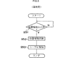
図6は基地局40のセンタサーバ41における処理を示している。ステップS51で位置情報の有無が判定され、位置情報がある場合にはその位置情報が送られてきたか否かが判定され、送られてきた場合にはその位置情報が読み込まれる(ステップS52)。読み込まれた情報はユーザ50側にメール等で報知される(ステップS53)。
【0025】
図7はユーザ50側の端末機51における処理の一例を示している。ステップS61でメール着信と判断されると、そのメールを読み込むことで油圧ショベル10の位置情報が把握される(ステップS62)。予めユーザ側で作成されている工程管理データが読み込まれ(ステップS63)、異常の有無が判断される(ステップS64)。例えば、送信されてきた位置情報が工程管理データにおける位置と大きく異なる場合には異常と判断され、その旨の情報が端末機61の画面上に表示される(ステップS65)。この異常情報が表示された場合には、担当者は関係者に連絡をとったり、場合によっては警察等に通報する。これによれば、油圧ショベル10の盗難があった場合でも速やかに回収することができる。またこのようなシステムを広めることで盗難そのものを激減できる。さらに盗難のおそれがあるときにのみ位置情報が送信されるので、送信コストの節減が図れる。
【0026】
以上では、エンジン停止時および始動時の位置情報をショベル側で比較するようにしたが、その比較は基地局側で行ってもよい。すなわち、ショベル側は単にエンジン停止時の位置情報P1とエンジン始動時の位置情報P2とをその都度送信するようにし、それらの情報を基地局側で比較して盗難のおそれがあるか否かを判断するようにしてもよい。
【0027】
また他の実施形態として、例えば基地局40側から油圧ショベル10に情報を送信可能に構成し、基地局40からの送信指示を油圧ショベル10のメインコントロールユニット12が受信すると、そのときの位置情報が送信されるようにしてもよい。これは、例えば基地局40あるいはユーザ側で特定の油圧ショベルの位置を知る必要が生じた場合に便利である。
【0028】
−第3の実施形態−
図8〜図11により本発明の第3の実施形態を説明する。本実施形態も第2の実施形態と同様に油圧ショベル10の盗難防止を図るものである。
【0029】
図8は本実施形態における構成図であり、図1と同様の構成要素には同一の符号を付す。基地局40のセンターサーバ41は、必要に応じて建設機械のレンタル会社70の端末機71に通信回線、例えば電話回線を介して電子メール等で情報を送信することが可能である。また、レンタル会社70の端末71と、そのレンタル会社70の建設機械を使用しているユーザー50の端末51との情報通信も可能とされる。その他の構成は図1と同様である。
【0030】
建設機械の管理部署の1つである基地局40は、ユーザー50が油圧ショベル10等の建設機械の作業現場を登録するサービスをそのWebサイト上で行う。例えば、ユーザー50が端末機51を用いて基地局40の所定のWebサイトにアクセスすると、全国を複数のエリアに分割したマップが画面上に表示される。ユーザー50が自社で使用している建設機械の作業現場を含むエリアをクリックすると、そのエリアが作業エリア情報として基地局40に送信される。
【0031】
なお、マップを用いずに、ユーザー50が州名や地域名を入力あるいは複数候補の中から選択して作業エリアを指定する方法でも良い。
【0032】
基地局40のセンタサーバ41は、図9に示すように、ユーザー50から作業エリア情報が送信されたことを確認すると(ステップS101)、その作業エリア情報をそのユーザー50に対応付けてデータベースに登録する(ステップS102)。
【0033】
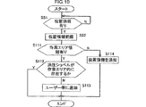
図10は基地局40のセンタサーバ41による他の処理を示している。図6で説明したと同様に、ステップS51で油圧ショベル10から位置情報が送られてきたか否かが判定され、送られてきた場合にはその位置情報が読み込まれる(ステップS52)。次に、当該油圧ショベル10を使用しているユーザー50に対応する作業エリア情報がデータベースに格納されているか否かが判定される(ステップS111)。作業エリア情報が格納されている場合には、その作業エリア情報と上記位置情報とに基づいて、当該油圧ショベル10が当該作業エリア内に存在するか否かが判定される(ステップS112)。作業エリア内に存在しない場合には、油圧ショベル10の位置が異常である(盗難されたおそれがある)と判断され、その旨がユーザー50または建設機械の他の管理部署であるレンタル会社70、あるいは双方に電子メール等で通知される(ステップS113)。またこのとき、油圧ショベルの位置情報も同時に通知される。レンタル会社70のみに通知された場合には、レンタル会社70からユーザー50に通知するようにすればよい。
【0034】
上記ステップS113での通知に同期して、油圧ショベル10のエンジンを停止する旨の信号を、メールサーバ30および通信衛星22を介して油圧ショベル10に送信するようにしてもよい。この場合、油圧ショベル10のメインコントロールユニット12は、例えば図11のような処理を行う。図11において、エンジン停止の旨の信号を受信したか否かを判定し(ステップS121)、受信した場合には強制的にエンジンを停止させる(ステップS122)。
【0035】
一方、図10のステップS111において、作業エリア情報が格納されていないと判断された場合には、油圧ショベル10の位置情報がユーザー50あるいはレンタル会社70に通知される(ステップS114)。この場合は盗難の有無をユーザー50あるいはレンタル会社側で判断することになる。
【0036】
なお、上記図11と同等の処理をレンタル会社70にて行うようにしてもよい。この場合には、基地局40から上記作業エリア情報がレンタル会社70に伝達されるようにしてもよいし、あるいはレンタル会社が作業エリア情報の登録サービスを行ってもよい。
【0037】
本実施形態では、ユーザー50に対応する作業エリア情報と位置情報の比較および異常判定をセンタサーバ41で行う構成としたが、予め作業エリア情報を油圧ショベル10に搭載したコントロールユニット12に送信し、この作業エリア情報をコントロールユニット12のメモリ部に記憶させ、上記作業エリア情報と位置情報の比較および異常判定をコントロールユニット12で行うようにしてもよい。その場合、異常と判定したときに、異常であることを位置情報とともにセンタサーバ41に送信する。このような構成を採用することにより、油圧ショベル10を停止させるか否かの判定をコントロールユニット12内で行うことができ、例えば通信状態が悪く位置情報を遅れない場合であっても油圧ショベル10の盗難を防止することができる。
【0038】
−第4の実施形態−
図8,図12,図13により本発明の第4の実施形態を説明する。
本実施形態は、盗難のおそれがあるか否かを油圧ショベル側で判断するようにしたものである。図8において、油圧ショベル10に設けられたスイッチSW2は、現在の油圧ショベル10の位置を記憶するために操作される操作スイッチである。
【0039】
図12に示すように、油圧ショベル10のメインコントロールユニット12は、スイッチSW2のオン(ステップS201)に伴って油圧ショベル10の現在の位置情報Pmをメモリ12Bに格納する(ステップS202)。オペレータは、例えば作業開始時あるいは終了時にこのスイッチSW2を操作して位置情報Pmを記憶させる。
【0040】
図13はメインコントロールユニット12による他の処理を示す。この処理は所定時間周期で繰り返し実行されるものである。
【0041】
GPSコントロールユニット11から油圧ショベル10の現在の位置情報Pcが読み込まれる(ステップS211)とともに、メモリ12Bに格納された位置情報Pmが読み出される(ステップS212)。Pc,Pm間の距離が求められ(ステップS213)、この距離が所定距離以上か否かが判断される(ステップS214)。所定距離以上の場合には盗難のおそれありと判断され、送信部12Aを介して位置情報Pcおよび盗難のおそれがある旨の情報が送信される(ステップS215)。基地局40は、これらの情報を受信すると、上述と同様にユーザー50あるいはレンタル会社70に電子メールで通報する。
【0042】
ここで、油圧ショベル10が盗難にあった場合に、盗難者がスイッチSW2を操作すると盗難の有無が正確に判定できなくなるので、スイッチSW2は目立たない箇所に設置するのが望ましい。
【0043】
本実施形態においても盗難のおそれの有無を基地局40あるいはレンタル会社70で判断するようにしてもよい。この場合には、上記スイッチSW2が操作されたときにそのときの位置情報が送信されるようし、これを基地局40あるいはレンタル会社70の記憶装置に位置情報Pmとして記憶させておく。そして、定期的に油圧ショベル10から送られてくる位置情報Pcと位置情報Pmとを比較し、上述と同様の盗難の有無を判定する。
【0044】
以上の実施形態では、GPS衛星を用いて油圧ショベルの位置を検知するようにしたが、これに代えて例えばPHSの位置情報提供サービス等を利用してもよい。
【0045】
産業上の利用可能性
以上では、油圧ショベルの管理システムについて説明したが、油圧ショベル以外の建設機械(例えば、クレーン等)の管理システムにも本発明を適用できる。
【図面の簡単な説明】
【図1】本発明の実施の形態における管理システムの概略構成図。
【図2】第1の実施形態における油圧ショベルの処理手順を示すフローチャート。
【図3】第1の実施形態における基地局の処理手順を示すフローチャート。
【図4】第2の実施形態における油圧ショベルの処理手順を示すフローチャート。
【図5】第2の実施形態における油圧ショベルの処理手順を示すフローチャート。
【図6】第2の実施形態における基地局の処理手順を示すフローチャート。
【図7】第2の実施形態におけるユーザ側の処理手順を示すフローチャート。
【図8】第3の実施形態における管理システムの概略構成図。
【図9】第3の実施形態における基地局側の処理手順を示すフローチャート。
【図10】第3の実施形態における基地局側の他の処理手順を示すフローチャート。
【図11】第3の実施形態における油圧ショベルの処理手順を示すフローチャート。
【図12】第4の実施形態における油圧ショベルの処理手順を示すフローチャート。
【図13】第4の実施形態における基地局側の処理手順を示すフローチャート。[0001]
TECHNICAL FIELD The present invention relates to a construction machine capable of transmitting position information to a base station and a management system using the construction machine.
[0002]
BACKGROUND ART Examples of systems for managing the operation status of vehicles such as automobiles and dump trucks include those described in JP-A-4-174387 and JP-A-4-174388. In the systems disclosed in these publications, position information of individual vehicles is detected using GPS satellites, and the position information is transmitted to the base station as needed. However, depending on the purpose of use of location information, it is not necessary for the base station to constantly recognize the location information. As described above, the method of transmitting as needed increases the transmission cost and is not economical.
[0003]
Moreover, what is described in the above publication is intended to manage the operation operating time from the operation distance of a vehicle such as an automobile or a dump truck. For example, construction machines such as a hydraulic excavator are away from the management department. It is common to be transported to a remote location and used in that remote location. And after the work is completed, since the collection work by the transport vehicle is troublesome, the construction machine is often left in the remote place. Under such circumstances, management of the construction machine by the manager is unprotected, and the manager is forced to bear a mental burden.
[0004]
In addition, the construction machine management department, that is, the manufacturer or rental company of the construction machine, needs to grasp the operating status of the construction machine supplied or provided and manage it so that the supplier or the recipient does not feel inconvenience. There is. For example, when a failure occurs in a construction machine, it takes time to confirm the location of the failed construction machine and arrange service personnel after confirmation after receiving notification of the failure from the supplier or the recipient. Is delayed.
[0005]
DISCLOSURE OF THE INVENTION The present invention aims to save the transmission cost by transmitting the position information of the construction machine as necessary, and to make the construction machine supplier or the recipient not feel as inconvenient as possible. And provide a construction machine management system.
[0006]
The invention of
The invention of
The invention of
According to a fourth aspect of the present invention, in the construction machine management system according to any one of the first to third aspects, the base station-side transmitting device is provided in the base station and transmits the positional information received by the receiving device to another engine. Is further provided.
According to the present invention, the determination device for determining whether or not the position information should be transmitted is provided, and the position information is transmitted from the construction machine only when it is determined that the position information should be transmitted. The transmission cost can be reduced compared to the case of transmission.
[0007]
BEST MODE FOR CARRYING OUT THE INVENTION First Embodiment
An embodiment in which the present invention is applied to a hydraulic excavator management system will be described with reference to FIGS.
[0008]
FIG. 1 is a schematic configuration diagram of a system according to the present invention. A
[0009]
The
[0010]
A
[0011]
Next, a specific example of the information transmission / reception process will be described with reference to the flowcharts of FIGS.
[0012]
FIG. 2 is a flowchart showing processing by the
[0013]
In step S1, it is determined whether or not the transmission operation switch SW1 has been operated. If it is determined that it has been operated, the position information of the
[0014]
In step S4, the presence / absence of a failure is determined based on the input information from the
[0015]
The transmitted information is sent to the
[0016]
The
[0017]
Failure information is not always necessary. For example, when the operator operates the transmission operation switch SW1 when the
[0018]
Alternatively, fuel can be replenished quickly by operating the transmission operation switch SW1 when the fuel remaining amount is low. For example, if the remaining amount of fuel is confirmed on the
[0019]
As described above, in this embodiment, since the position information is transmitted in accordance with the switch operation of the operator, the communication cost can be saved as compared with the case where the position information is transmitted as needed.
[0020]
In the present embodiment, the information is transmitted by operating the switch SW1, but the failure information and the position information may be transmitted when the occurrence of the failure is detected. As a result, the information is sent to the
[0021]
-Second Embodiment-
A second embodiment of the present invention will be described with reference to FIGS.
In the present embodiment, it is determined that the
[0022]
FIG. 4 shows processing when the engine is stopped in the
[0023]
FIG. 5 shows processing at the time of engine start in the
[0024]
FIG. 6 shows processing in the
[0025]
FIG. 7 shows an example of processing in the terminal 51 on the
[0026]
In the above, the position information when the engine is stopped and when the engine is started is compared on the shovel side, but the comparison may be performed on the base station side. That is, the shovel side simply transmits the position information P1 when the engine is stopped and the position information P2 when the engine is started, and compares the information on the base station side to determine whether or not there is a possibility of theft. You may make it judge.
[0027]
In another embodiment, for example, information can be transmitted from the
[0028]
-Third embodiment-
A third embodiment of the present invention will be described with reference to FIGS. This embodiment is also intended to prevent the
[0029]
FIG. 8 is a configuration diagram in the present embodiment, and the same components as those in FIG. 1 are denoted by the same reference numerals. The
[0030]
The
[0031]
Instead of using a map, the
[0032]
As shown in FIG. 9, when the
[0033]
FIG. 10 shows another process performed by the
[0034]
A signal to stop the engine of the
[0035]
On the other hand, if it is determined in step S111 in FIG. 10 that the work area information is not stored, the position information of the
[0036]
Note that the
[0037]
In the present embodiment, the
[0038]
-Fourth Embodiment-
A fourth embodiment of the present invention will be described with reference to FIGS.
In the present embodiment, the hydraulic excavator side determines whether or not there is a possibility of theft. In FIG. 8, a switch SW <b> 2 provided in the
[0039]
As shown in FIG. 12, the
[0040]
FIG. 13 shows another process by the
[0041]
The current position information Pc of the
[0042]
Here, when the
[0043]
Also in this embodiment, the
[0044]
In the above embodiment, the position of the excavator is detected using a GPS satellite, but instead of this, for example, a PHS position information providing service or the like may be used.
[0045]
INDUSTRIAL APPLICABILITY The hydraulic excavator management system has been described above. However, the present invention can also be applied to a management system for construction machines other than the hydraulic excavator (for example, a crane).
[Brief description of the drawings]
FIG. 1 is a schematic configuration diagram of a management system according to an embodiment of the present invention.
FIG. 2 is a flowchart showing a processing procedure of the hydraulic excavator in the first embodiment.
FIG. 3 is a flowchart showing a processing procedure of the base station in the first embodiment.
FIG. 4 is a flowchart illustrating a processing procedure of a hydraulic excavator according to a second embodiment.
FIG. 5 is a flowchart illustrating a processing procedure of a hydraulic excavator according to a second embodiment.
FIG. 6 is a flowchart showing a processing procedure of a base station in the second embodiment.
FIG. 7 is a flowchart showing a processing procedure on the user side in the second embodiment.
FIG. 8 is a schematic configuration diagram of a management system according to a third embodiment.
FIG. 9 is a flowchart showing a processing procedure on the base station side in the third embodiment.
FIG. 10 is a flowchart showing another processing procedure on the base station side in the third embodiment.
FIG. 11 is a flowchart illustrating a processing procedure of a hydraulic excavator according to a third embodiment.
FIG. 12 is a flowchart showing a processing procedure of the hydraulic excavator in the fourth embodiment.
FIG. 13 is a flowchart showing a processing procedure on the base station side in the fourth embodiment.
Claims (4)
前記建設機械は、
当該建設機械の位置情報を検知する位置検知装置と、
前記位置情報を送信すべきか否かを判定し、送信すべきと判断したときに送信信号を出力する判定装置と、
建設機械の故障の有無を検出する故障検出装置と、
前記送信信号に応答して、そのとき検知された前記位置情報を基地局に報知すべく送信するとともに、前記送信信号の出力時に故障が検出されている場合には、前記位置情報に加えて故障情報をも送信する送信装置と
を有することを特徴とする建設機械の管理システム。A management system for receiving information transmitted from a construction machine by a receiving device provided in a base station,
The construction machine is
A position detection device for detecting position information of the construction machine;
A determination device that determines whether or not to transmit the position information and outputs a transmission signal when it is determined that the position information should be transmitted;
A failure detection device for detecting whether there is a failure in the construction machine;
In response to the transmission signal, the location information detected at that time is transmitted to be notified to the base station. A construction machine management system comprising: a transmission device that also transmits information.
前記建設機械は、オペレータが操作可能な操作スイッチをさらに有し、 The construction machine further includes an operation switch operable by an operator,
前記判定装置は、前記操作スイッチの操作の有無を判定し、前記操作スイッチの操作があったと判定すると前記操作信号を出力することを特徴とする建設機械の管理システム。 A construction machine management system, wherein the determination device determines whether or not the operation switch is operated, and outputs the operation signal when determining that the operation switch is operated.
前記建設機械は、
当該建設機械の位置情報を検知する位置検知装置と、
建設機械の故障の有無を検出する故障検出装置と、
前記故障検出装置によって故障が検出されたか否かを判定し、故障が検出されたときに送信信号を出力する判定装置と、
前記送信信号に応答して、そのとき検知された前記位置情報および前記検出された故障に関する故障情報を送信する送信装置と
を有することを特徴とする建設機械の管理システム。A management system for receiving information transmitted from a construction machine by a receiving device provided in a base station,
The construction machine is
A position detection device for detecting position information of the construction machine;
A failure detection device for detecting whether there is a failure in the construction machine;
It is determined whether or not a failure is detected by the failure detection device, and a determination device that outputs a transmission signal when a failure is detected;
A construction machine management system comprising: a transmission device that transmits the position information detected at that time and the failure information relating to the detected failure in response to the transmission signal.
前記基地局に設けられ、前記受信装置が受信した位置情報を他の機関へ送信する基地局側送信装置を更に備えることを特徴とする建設機械の管理システム。In the management system of the construction machine in any one of Claim 1 to 3 ,
A construction machine management system, further comprising: a base station-side transmitting device that is provided in the base station and transmits position information received by the receiving device to another organization.
Applications Claiming Priority (3)
| Application Number | Priority Date | Filing Date | Title |
|---|---|---|---|
| JP2000099086 | 2000-03-31 | ||
| JP2000099086 | 2000-03-31 | ||
| PCT/JP2001/002809 WO2001073220A1 (en) | 2000-03-31 | 2001-03-30 | Construction machine management system and construction machine |
Related Child Applications (1)
| Application Number | Title | Priority Date | Filing Date |
|---|---|---|---|
| JP2005334178A Division JP4176762B2 (en) | 2000-03-31 | 2005-11-18 | Construction machine management system |
Publications (2)
| Publication Number | Publication Date |
|---|---|
| JPWO2001073220A1 JPWO2001073220A1 (en) | 2004-01-08 |
| JP3836725B2 true JP3836725B2 (en) | 2006-10-25 |
Family
ID=18613483
Family Applications (1)
| Application Number | Title | Priority Date | Filing Date |
|---|---|---|---|
| JP2001570922A Expired - Lifetime JP3836725B2 (en) | 2000-03-31 | 2001-03-30 | Construction machine management system and construction machine |
Country Status (6)
| Country | Link |
|---|---|
| US (1) | US7010403B2 (en) |
| EP (2) | EP1273721B1 (en) |
| JP (1) | JP3836725B2 (en) |
| KR (2) | KR100639812B1 (en) |
| CN (1) | CN1227420C (en) |
| WO (1) | WO2001073220A1 (en) |
Families Citing this family (46)
| Publication number | Priority date | Publication date | Assignee | Title |
|---|---|---|---|---|
| ATE447752T1 (en) * | 1999-03-17 | 2009-11-15 | Komatsu Mfg Co Ltd | COMMUNICATION ARRANGEMENT OF A MOBILE UNIT |
| JP2004301606A (en) * | 2003-03-31 | 2004-10-28 | Denso Corp | Obstacle information providing system for vehicles |
| US7532640B2 (en) | 2003-07-02 | 2009-05-12 | Caterpillar Inc. | Systems and methods for performing protocol conversions in a machine |
| US7983820B2 (en) | 2003-07-02 | 2011-07-19 | Caterpillar Inc. | Systems and methods for providing proxy control functions in a work machine |
| US7516244B2 (en) | 2003-07-02 | 2009-04-07 | Caterpillar Inc. | Systems and methods for providing server operations in a work machine |
| US20050234788A1 (en) * | 2004-04-19 | 2005-10-20 | Hudson John G | Method and system for billing for internet services for ad-hoc network nodes |
| US8023936B2 (en) * | 2004-04-19 | 2011-09-20 | The Boeing Company | Method and system for monitoring ad-hoc network nodes |
| DE102004061781B4 (en) * | 2004-05-04 | 2017-11-23 | Volkswagen Ag | Key for a motor vehicle |
| US7245258B2 (en) | 2004-06-25 | 2007-07-17 | Intel Corporation | Location processing apparatus, systems, and methods |
| JP2006038581A (en) * | 2004-07-26 | 2006-02-09 | Topcon Corp | Surveying instrument management system |
| US7352283B2 (en) | 2004-12-08 | 2008-04-01 | Intel Corporation | Computing platform security apparatus, systems, and methods |
| US7681192B2 (en) * | 2005-01-31 | 2010-03-16 | Caterpillar Trimble Control Technologies Llc | Location-centric project data delivery system for construction |
| US7245999B2 (en) | 2005-01-31 | 2007-07-17 | Trimble Navigation Limited | Construction machine having location based auto-start |
| KR100631070B1 (en) * | 2005-02-23 | 2006-10-02 | 볼보 컨스트럭션 이키프먼트 홀딩 스웨덴 에이비 | Maintenance system using construction machine start key for data storage and construction machine start key for data storage |
| US8965841B2 (en) | 2006-10-05 | 2015-02-24 | Trimble Navigation Limited | Method for automatic asset classification |
| US9773222B2 (en) | 2006-10-05 | 2017-09-26 | Trimble Inc. | Externally augmented asset management |
| US9111234B2 (en) | 2006-10-05 | 2015-08-18 | Trimble Navigation Limited | Enabling notifications pertaining to an asset |
| US9747329B2 (en) | 2006-10-05 | 2017-08-29 | Trimble Inc. | Limiting access to asset management information |
| US9519876B2 (en) | 2006-10-05 | 2016-12-13 | Trimble Navigation Limited | Method for providing maintenance to an asset |
| US8645176B2 (en) | 2006-10-05 | 2014-02-04 | Trimble Navigation Limited | Utilizing historical data in an asset management environment |
| US9747571B2 (en) | 2006-10-05 | 2017-08-29 | Trimble Inc. | Integrated asset management |
| US8004397B2 (en) | 2006-10-05 | 2011-08-23 | Trimble Navigation Limited | Receiving information pertaining to a construction project |
| US9811949B2 (en) | 2006-10-05 | 2017-11-07 | Trimble Inc. | Method for providing status information pertaining to an asset |
| US8255358B2 (en) | 2006-10-05 | 2012-08-28 | Trimble Navigation Limited | System and method for providing asset management information to a customer |
| US9536405B2 (en) | 2006-10-05 | 2017-01-03 | Trimble Inc. | Unreported event status change determination and alerting |
| US8666936B2 (en) | 2006-10-05 | 2014-03-04 | Trimble Navigation Limited | System and method for asset management |
| US7898403B2 (en) | 2006-10-05 | 2011-03-01 | Trimble Navigation Limited | Detecting construction equipment process failure |
| US9041561B2 (en) | 2006-10-05 | 2015-05-26 | Trimble Navigation Limited | Method for controlling power usage of a reporting device |
| US8600932B2 (en) | 2007-05-07 | 2013-12-03 | Trimble Navigation Limited | Telematic asset microfluidic analysis |
| JP2009151377A (en) * | 2007-12-18 | 2009-07-09 | Fanuc Ltd | Numerical control device with transfer preventing function and transfer prevention system |
| KR101663314B1 (en) * | 2009-10-14 | 2016-10-06 | 두산인프라코어 주식회사 | System and method for tracking of construction machinery |
| CN102592437A (en) * | 2011-01-17 | 2012-07-18 | 新光国际航太科技股份有限公司 | Vehicle dispatching system and dispatching method |
| JP5687130B2 (en) * | 2011-05-10 | 2015-03-18 | 株式会社小松製作所 | Automatic supply system for consumables |
| US9739763B2 (en) | 2011-05-16 | 2017-08-22 | Trimble Inc. | Telematic locomotive microfluidic analysis |
| US9760685B2 (en) | 2011-05-16 | 2017-09-12 | Trimble Inc. | Telematic microfluidic analysis using handheld device |
| JP2013037619A (en) * | 2011-08-10 | 2013-02-21 | Sumitomo (Shi) Construction Machinery Co Ltd | Information management system, control device, portable terminal and display control method in construction machine |
| JP2013186740A (en) * | 2012-03-08 | 2013-09-19 | Fanuc Ltd | Management system for machine |
| JP5873388B2 (en) | 2012-05-10 | 2016-03-01 | 日立建機株式会社 | Industrial vehicle management system |
| JP6236432B2 (en) | 2013-03-08 | 2017-11-22 | 日立建機株式会社 | Work machine management server and work machine management method |
| US9959738B2 (en) * | 2013-04-08 | 2018-05-01 | Centega Services, Llc | Reciprocating machinery monitoring system and method |
| WO2015084089A1 (en) * | 2013-12-05 | 2015-06-11 | 두산인프라코어 주식회사 | Fault diagnostic system for work system of construction equipment and fault diagnostic method using same |
| CN104787007A (en) * | 2015-03-20 | 2015-07-22 | 句容五星机械制造有限公司 | Fault detection method for phenomenon that self-lifting position of tilting cart carriage cannot be laid down |
| CN109583801B (en) * | 2017-09-29 | 2022-04-05 | 上海鸿研物流技术有限公司 | Monitoring method and system for shared recyclable logistics appliances |
| US12112581B2 (en) * | 2018-08-14 | 2024-10-08 | Daniel Gaudreault | System and method for remote diagnostics and monitoring of heavy equipment |
| KR102868911B1 (en) * | 2020-07-17 | 2025-10-02 | 에이치디현대인프라코어 주식회사 | Emergency device for construction machine and method for controlling the emergency device for construction machine thereof |
| WO2024224780A1 (en) * | 2023-04-26 | 2024-10-31 | 株式会社デンソー | Monitoring device for vehicle and monitoring method for vehicle |
Family Cites Families (21)
| Publication number | Priority date | Publication date | Assignee | Title |
|---|---|---|---|---|
| US4119943A (en) * | 1977-01-14 | 1978-10-10 | Kabushiki Kaisha Komatsu Seisakusho | Monitor system for construction vehicles |
| JPS5854137A (en) * | 1981-09-25 | 1983-03-31 | Komatsu Ltd | Monitoring device for construction machinery |
| JPH0774295B2 (en) * | 1987-12-22 | 1995-08-09 | 三井東圧化学株式会社 | Method for producing polypropylene resin composition |
| JPH04174387A (en) | 1990-11-06 | 1992-06-22 | Komatsu Ltd | Mobile monitoring device |
| JPH04174388A (en) | 1990-11-06 | 1992-06-22 | Komatsu Ltd | Construction machinery monitoring device |
| JP3306214B2 (en) * | 1994-04-04 | 2002-07-24 | 日立建機株式会社 | Mobile work machine management system and mobile work machine |
| JPH08136639A (en) | 1994-11-08 | 1996-05-31 | Japan Radio Co Ltd | How to track a stolen vehicle |
| JPH08144904A (en) * | 1994-11-16 | 1996-06-04 | Komatsu Ltd | Remote start / stop device for construction machine engine |
| JPH08144312A (en) | 1994-11-22 | 1996-06-04 | Hitachi Constr Mach Co Ltd | Mobile work machine management system |
| JPH09188224A (en) * | 1996-01-11 | 1997-07-22 | Tokai Rika Co Ltd | Communication system for vehicle |
| JP3550916B2 (en) | 1996-11-12 | 2004-08-04 | トヨタ自動車株式会社 | Vehicle theft detection device |
| JP3745484B2 (en) * | 1997-02-12 | 2006-02-15 | 株式会社小松製作所 | Vehicle monitoring device |
| JPH10308983A (en) * | 1997-05-02 | 1998-11-17 | Nippon Joho Tsushin Consulting Kk | Remote control method and method |
| JP3366837B2 (en) * | 1997-08-15 | 2003-01-14 | 株式会社小松製作所 | Machine abnormality monitoring device and method |
| JP4023643B2 (en) * | 1998-06-02 | 2007-12-19 | 株式会社小松製作所 | Apparatus performance data measuring method and apparatus for construction machinery |
| JP2000027236A (en) | 1998-07-07 | 2000-01-25 | Komatsu Ltd | Data storage device and data processing device for construction machinery |
| EP0989525A3 (en) | 1998-08-31 | 2001-09-19 | Kabushiki Kaisha Kobe Seiko Sho | Management system for construction machines |
| JP3834511B2 (en) * | 2000-03-23 | 2006-10-18 | 日立建機株式会社 | Work machine operating data transmission method and apparatus |
| US20020107624A1 (en) * | 2001-02-07 | 2002-08-08 | Deere & Company, A Delaware Corporation | Monitoring equipment for an agricultural machine |
| US20020116107A1 (en) * | 2001-02-07 | 2002-08-22 | Deere & Company | Method of monitoring equipment of an agricultural machine |
| KR100523228B1 (en) * | 2001-05-08 | 2005-10-20 | 히다치 겡키 가부시키 가이샤 | Working machine, trouble diagnosis system of working machine, and maintenance system of working machine |
-
2001
- 2001-03-30 WO PCT/JP2001/002809 patent/WO2001073220A1/en not_active Ceased
- 2001-03-30 EP EP01917741.9A patent/EP1273721B1/en not_active Expired - Lifetime
- 2001-03-30 KR KR1020067002905A patent/KR100639812B1/en not_active Expired - Lifetime
- 2001-03-30 JP JP2001570922A patent/JP3836725B2/en not_active Expired - Lifetime
- 2001-03-30 EP EP10180864A patent/EP2261426B1/en not_active Expired - Lifetime
- 2001-03-30 KR KR1020027012819A patent/KR100572252B1/en not_active Expired - Lifetime
- 2001-03-30 US US10/240,009 patent/US7010403B2/en not_active Expired - Lifetime
- 2001-03-30 CN CNB018075665A patent/CN1227420C/en not_active Expired - Lifetime
Also Published As
| Publication number | Publication date |
|---|---|
| US7010403B2 (en) | 2006-03-07 |
| EP2261426B1 (en) | 2012-09-26 |
| US20030093203A1 (en) | 2003-05-15 |
| KR100639812B1 (en) | 2006-10-30 |
| CN1227420C (en) | 2005-11-16 |
| JPWO2001073220A1 (en) | 2004-01-08 |
| KR100572252B1 (en) | 2006-04-19 |
| KR20060018929A (en) | 2006-03-02 |
| EP1273721A4 (en) | 2009-07-29 |
| EP2261426A1 (en) | 2010-12-15 |
| CN1422353A (en) | 2003-06-04 |
| WO2001073220A1 (en) | 2001-10-04 |
| EP1273721B1 (en) | 2013-05-22 |
| EP1273721A1 (en) | 2003-01-08 |
| KR20020091160A (en) | 2002-12-05 |
Similar Documents
| Publication | Publication Date | Title |
|---|---|---|
| JP3836725B2 (en) | Construction machine management system and construction machine | |
| US6549833B2 (en) | Repair and maintenance support system and a car corresponding to the system | |
| US7002465B2 (en) | Security system of construction machine | |
| CN101132187A (en) | Method and system for reporting machine status | |
| EP2226778A1 (en) | A saving power system and method for managing communication of a moving object | |
| WO2009074066A1 (en) | A system and method for locating and monitoring machine and a device for realizing communication | |
| JP4656772B2 (en) | Mobile communication device | |
| EP1191156B1 (en) | System for supplying fuel to construction machine | |
| JP2002091547A (en) | Work machine management system | |
| JPWO2001073221A1 (en) | FUEL REFILLING SYSTEM FOR CONSTRUCTION MACHINE AND CONSTRUCTION MACHINE | |
| JP3981840B2 (en) | Operation status notification system | |
| JP4176762B2 (en) | Construction machine management system | |
| JP4593029B2 (en) | Mobile communication device | |
| JP5274070B2 (en) | Work machine position management system and work area data update method | |
| JP3720719B2 (en) | Vehicle theft alarm system and vehicle theft alarm method | |
| JP4574905B2 (en) | Mobile communication device | |
| JP2003099894A (en) | Moving body information managing device | |
| JP2002331914A (en) | Vehicle position detecting system | |
| CN100573610C (en) | vehicle anti-theft monitoring system | |
| JP2003141685A (en) | Controller for operation of moving body | |
| JP2008240462A (en) | Operator management system | |
| JP3959218B2 (en) | Transport vehicle work / operation management system | |
| JP2026050207A (en) | Management system for industrial machinery | |
| JP2002042282A (en) | Theft preventing system for vehicle |
Legal Events
| Date | Code | Title | Description |
|---|---|---|---|
| A131 | Notification of reasons for refusal |
Free format text: JAPANESE INTERMEDIATE CODE: A131 Effective date: 20050920 |
|
| A521 | Request for written amendment filed |
Free format text: JAPANESE INTERMEDIATE CODE: A523 Effective date: 20051118 |
|
| TRDD | Decision of grant or rejection written | ||
| A01 | Written decision to grant a patent or to grant a registration (utility model) |
Free format text: JAPANESE INTERMEDIATE CODE: A01 Effective date: 20060711 |
|
| A61 | First payment of annual fees (during grant procedure) |
Free format text: JAPANESE INTERMEDIATE CODE: A61 Effective date: 20060727 |
|
| R150 | Certificate of patent or registration of utility model |
Ref document number: 3836725 Country of ref document: JP Free format text: JAPANESE INTERMEDIATE CODE: R150 Free format text: JAPANESE INTERMEDIATE CODE: R150 |
|
| FPAY | Renewal fee payment (event date is renewal date of database) |
Free format text: PAYMENT UNTIL: 20090804 Year of fee payment: 3 |
|
| FPAY | Renewal fee payment (event date is renewal date of database) |
Free format text: PAYMENT UNTIL: 20100804 Year of fee payment: 4 |
|
| FPAY | Renewal fee payment (event date is renewal date of database) |
Free format text: PAYMENT UNTIL: 20110804 Year of fee payment: 5 |
|
| FPAY | Renewal fee payment (event date is renewal date of database) |
Free format text: PAYMENT UNTIL: 20110804 Year of fee payment: 5 |
|
| FPAY | Renewal fee payment (event date is renewal date of database) |
Free format text: PAYMENT UNTIL: 20120804 Year of fee payment: 6 |
|
| FPAY | Renewal fee payment (event date is renewal date of database) |
Free format text: PAYMENT UNTIL: 20130804 Year of fee payment: 7 |
|
| EXPY | Cancellation because of completion of term |