JP3838112B2 - Water purification cartridge - Google Patents

Water purification cartridge Download PDF

Info

Publication number
JP3838112B2
JP3838112B2 JP2002024625A JP2002024625A JP3838112B2 JP 3838112 B2 JP3838112 B2 JP 3838112B2 JP 2002024625 A JP2002024625 A JP 2002024625A JP 2002024625 A JP2002024625 A JP 2002024625A JP 3838112 B2 JP3838112 B2 JP 3838112B2
Authority
JP
Japan
Prior art keywords
water
inner casing
purification material
adsorption
pressing member
Prior art date
Legal status (The legal status is an assumption and is not a legal conclusion. Google has not performed a legal analysis and makes no representation as to the accuracy of the status listed.)
Expired - Fee Related
Application number
JP2002024625A
Other languages
Japanese (ja)
Other versions
JP2002301471A (en
Inventor
弘之 高野
Current Assignee (The listed assignees may be inaccurate. Google has not performed a legal analysis and makes no representation or warranty as to the accuracy of the list.)
Panasonic Electric Works Co Ltd
Original Assignee
Matsushita Electric Works Ltd
Priority date (The priority date is an assumption and is not a legal conclusion. Google has not performed a legal analysis and makes no representation as to the accuracy of the date listed.)
Filing date
Publication date
Application filed by Matsushita Electric Works Ltd filed Critical Matsushita Electric Works Ltd
Priority to JP2002024625A priority Critical patent/JP3838112B2/en
Publication of JP2002301471A publication Critical patent/JP2002301471A/en
Application granted granted Critical
Publication of JP3838112B2 publication Critical patent/JP3838112B2/en
Anticipated expiration legal-status Critical
Expired - Fee Related legal-status Critical Current

Links

Images

Landscapes

  • Water Treatment By Sorption (AREA)

Description

【0001】
【発明の属する技術分野】
本発明は、水道水などに含まれる残留塩素やトリハロメタン等を除去・浄化したり、さらには水中のミネラル等の金属成分を調整する浄水カートリッジに関するものである。
【0002】
【従来の技術】
水道水には、塩素消毒による残留塩素いわゆるカルキや、トリハロメタン等の様々な成分が含まれる。生活者が水道水を利用、特に飲用に使用する際には、前記成分やその他の成分について味覚や健康の点で不満または不安を持っている。そこで、一般的には活性炭等からなる吸着浄化材と中空糸膜フィルター等からなる濾過材とを備えた浄水カートリッジを装備したアルカリイオン水生成器等の浄水器を使用し、この浄水カートリッジにより浄化した浄水を飲用等に利用している。
【0003】
この浄水カートリッジでは、そのろ過あるいは浄化能力はろ材(吸着浄化材及び濾過材)の大きさや量によりその優劣が決まってくるものである。例えば水道水中からトリハロメタン等を除去するためには、活性炭に代表される上記吸着浄化材を内包する浄水カートリッジを利用するが、その除去能力は浄水カートリッジの吸着浄化材の内容量により決まるものである。
【0004】
また、長期に亘りアルカリイオン水生成器等の浄水器の除去能力を維持するためには、一般的に浄水カートリッジを交換する、大量の吸着浄化材を備えた大型の浄水カートリッジを利用する、あるいは吸着浄化材を再生させることが考えられてきた。吸着浄化材を再生させることは水蒸気や熱水の利用が必要になることからエネルギの消費が増長されるものであって非効率であり、また、大量の吸着浄化材を内装した大型の浄水カートリッジを利用することは浄水カートリッジのろ過部分における摩擦損失により浄水カートリッジに流れる流量を少なくさせてしまって非効率であり、また、浄水カートリッジを頻繁に交換することは吸着浄化材の浪費と浄水器の利用者の経済的な負担を増長させるものであることから、適度の量の吸着浄化材を備えると共に交換し得る浄水カートリッジを浄水器に備えたものが実用化されている。
【0005】
このアルカリイオン水生成器等の浄水器に内装される浄水カートリッジには、例えば、図6及び図7に示すようなものがある。この浄水カートリッジは、有底筒状の外部ケーシング本体11と上記外部ケーシング本体11の開口を閉塞する外部ケーシング蓋体12とで外部ケーシングを構成し、吸着浄化材3を収納した内部ケーシングを上記外部ケーシングの内部に配置して構成されたものである。外部ケーシング本体11の底面には水を外部ケーシングの内部に流入させる流入口1が設けられており、また、外部ケーシング蓋体12の中央部には浄水を吐出させる流出口2が設けられている。内部ケーシングも外部ケーシング同様に有底筒状の内部ケーシング本体4と上記内部ケーシング本体4の開口を閉塞する内部ケーシング蓋体5とで構成されており、内部ケーシング本体4の筒側面に亘って外部ケーシングの流入口1から流入した水を内部ケーシング内部に導入し得る透水性壁面部6を形成させ、また、内部ケーシング本体4の内部には上記透水性壁面部6に沿って筒状の吸着浄化材3を配置させている。この吸着浄化材3の筒内部には内部ケーシング蓋体5の中央を貫通して終端を外部ケーシングの流出口2に位置させた連通管7が設けられている。なお、この連通管7はその終端部分で内部ケーシング蓋体5及び外部ケーシング蓋体12にパッキン25を介した水密保持構造で連結されている。つまり、この連通管7は吸着浄化材3を通過した浄水を外部ケーシングの流出口2に至らしめる機能を有している。また、内部ケーシング本体4の開口を閉塞した内部ケーシング蓋体5と吸着浄化材3の間には弾性板20及び押さえ板21を介在させてある。上記弾性板20及び押さえ板21は内部ケーシング蓋体5によって吸着浄化材3を内部ケーシング本体4の底面に押し付けて固定させているものである。また、内部ケーシング本体4と内部ケーシング蓋体5との間にはOリング19を介在させている。このOリング19は内部ケーシング本体4と内部ケーシング蓋体5との間に水密保持構造を形成させるものであって、この水密保持構造により、内部ケーシング内の吸着浄化材3を通過しないで連通管7を経て流出口2に至り、浄水カートリッジに流入させた水が浄水されないで吐出されてしまう(ショートパスまたはチャンネリングと言う)ことを避けることに成功しているものである。つまりは、流入口1から外部ケーシング内部に流入した全ての水は、透水性壁面部6を通って内部ケーシング内に導入されると共に吸着浄化材3を通過して浄水され、連通管7を通って流出口2から外部ケーシングの外に吐出されるものである。
【0006】
なお、図8に示すように、上述した活性炭等からなる吸着浄化材3を収納した浄水カートリッジ(以下、第1浄水カートリッジ)に中空糸膜フィルター等からなる濾過材24を収納した第2浄水カートリッジを連設させ、上記第1浄水カートリッジの吸着浄化材3を通った水が第2浄水カートリッジの濾過材24を通って更に程度の高い浄水を提供できるようにした浄水カートリッジもある。
【0007】
【発明が解決しようとする課題】
ところで、上記浄水カートリッジにおいて、内部ケーシング蓋体5と内部ケーシング本体4との間のOリング19で形成した水密保持構造がなかった場合には、外部ケーシングの流入口1から外部ケーシング内部に流入した水の一部は、内部ケーシング蓋体5と内部ケーシング本体4との間から内部ケーシング内に流入すると共に吸着浄化材3を通過しないで連通管7に至り、外部ケーシングの流出口2から吐出されてしまうものであり、つまり、ショートパスまたはチャネリングが生じてしまい、浄水カートリッジが生成する浄水の質を下げてしまうものである。
【0008】
しかして、上記内部ケーシング蓋体5と内部ケーシング本体4との間の水密保持構造は上記構造の浄水カートリッジにおいては必要な構造であるが、上記内部ケーシング蓋体5と内部ケーシング本体4との間の水密保持構造は浄水カートリッジの容積に対してやや大きな割合を占めてしまうものであり、その分、浄水カートリッジの容積に占める吸着浄化材3の割合を下げてしまい、浄水カートリッジのろ過能力(吸着浄化能力)を低下させてしまうものであった。
【0009】
本発明は上記事由に鑑みてなされたものであり、従来と同じ大きさの浄水カートリッジであっても、比較して浄水カートリッジの容積に占める吸着浄化材の割合を上げ、そのろ過能力(吸着浄化能力)が高くできる浄水カートリッジを提供することを課題とする。
【0010】
【課題を解決するための手段】
上記課題を解決するために本発明の請求項1に係る浄水カートリッジにあっては、流入口1と流出口2を設けた外部ケーシングの内部に内部ケーシングを配設し、上記内部ケーシングが吸着浄化材3を内部に収納した有底筒状の内部ケーシング本体4と上記内部ケーシング本体4の開口を閉塞する内部ケーシング蓋体5とを有し、上記外部ケーシングの流入口1から外部ケーシング内に流入した水を内部ケーシング本体4の内部に導入する透水性壁面部6を上記内部ケーシング本体5の少なくとも筒側面部分に設け、内部ケーシング本体4内部の吸着浄化材3を通って浄化した浄水を外部ケーシングの流出口2に至らしめる連通管7を上記内部ケーシング蓋体5を貫通して設け、上記内部ケーシング本体4の開口を閉塞した内部ケーシング蓋体5と吸着浄化材3との間に上記吸着浄化材3を固定する押さえ部材8を介在させると共に、上記押さえ部材8が吸着浄化材3を含有してシート状に形成されたことを特徴とする。これにより、内部ケーシング本体4と内部ケーシング蓋体5との間から内部ケーシング内に流入した水も、上記吸着浄化材3を含有してシート状に形成した押さえ部材8を介して浄水となって連通管7に至るものであって、つまり、浄水カートリッジに流入させた水の全てが浄水されて流出口2から吐出されるといった浄水カートリッジの本来の機能を確保できるものであり、また、これによって本発明の浄水カートリッジは従来の浄水カートリッジの内部ケーシング本体4と内部ケーシング蓋体5との間にあった水密保持構造を備えなくて済むものであり、上記水密保持構造を備えないことで、浄水カートリッジの構造を簡易化することができると共に、浄水カートリッジの容積のうち上記水密保持構造が占めていた容積分余計に吸着浄化材3を内部ケーシング本体4内に詰めることができて浄水カートリッジの容積に占める吸着浄化材3の割合を上げることができ、つまり、従来と比較して浄水カートリッジの大きさはそのままに浄水カートリッジの吸着浄化能力を向上させることができるものである。更に言うと、押さえ部材8にも吸着浄化材3を含有させていることは、浄水カートリッジ内の吸着浄化材3の占める割合の向上に資するものであって吸着浄化能力の向上が図られているのである。
【0011】
また、本発明の請求項2に係る浄水カートリッジにあっては、請求項1において、上記押さえ部材8が、少なくとも内部ケーシング蓋体5と吸着浄化材3との対向方向に弾性を有してなることを特徴とする。これにより、内部ケーシング蓋体5が内部ケーシング本体4の開口を閉塞した際に、内部ケーシング本体4に配置した吸着浄化材3と内部ケーシング蓋体5との間で上記押さえ部材8が圧縮されて弾性変形をし、上記弾性変形をして吸着浄化材3に略隙間無く当接した押さえ部材8が内部ケーシング蓋体5から受ける内部ケーシング本体4の底面方向の荷重を吸着浄化材3に略一様に作用させるものであって、つまり、吸着浄化材3を漏れなく確実に内部ケーシング本体4の底面方向に押し付けることができるものである。
【0012】
また、本発明の請求項3に係る浄水カートリッジにあっては、請求項2において、上記押さえ部材8を不織布9に吸着浄化材3を混入させて形成したことを特徴とする。これにより、上記不織布9によって押さえ部材8には弾性及び透水性が備えられると共に、上記不織布9に吸着浄化材3を混入したことでより多くの吸着浄化材3を押さえ部材8に含有することができ、ひいては、浄水カートリッジの容積のうち吸着浄化材3の占める割合を向上させることができる。
【0013】
また、本発明の請求項4に係る浄水カートリッジにあっては、請求項2において、押さえ部材8を活性炭素繊維で形成した不織布9で構成したことを特徴とする。これにより、不織布9によって押さえ部材8には弾性及び透水性が備えられると共に、活性炭素繊維で不織布9を形成させたことでより多くの活性炭(吸着浄化材3)を押さえ部材8に含有することができ、ひいては、浄水カートリッジの容積のうち吸着浄化材3の占める割合を向上させることができる。
【0014】
また、本発明の請求項5に係る浄水カートリッジにあっては、請求項2において、押さえ部材8を弾性多孔体10と吸着浄化材3とで形成したことを特徴とする。これにより、弾性多孔体10によって押さえ部材8には透水性及び弾性が備えられるものであり、上記押さえ部材8を吸着浄化材3で構成したことで押さえ部材8に吸着浄化材3を含有することができ、ひいては、浄水カートリッジの容積のうち吸着浄化材3の占める割合を向上させることができる。
【0015】
また、本発明の請求項6に係る浄水カートリッジにあっては、請求項2において、押さえ部材8を弾性多孔体10で形成し、上記弾性多孔体10の内部に吸着浄化材3を添着したことを特徴とする。これにより、弾性多孔体10によって押さえ部材8には透水性及び弾性が備えられるものであり、更に上記弾性多孔体10の内部に吸着浄化材3を添着したことで押さえ部材8に吸着浄化材3を含有することができ、ひいては、浄水カートリッジの容積のうち吸着浄化材3の占める割合を向上させることができる。
【0016】
【発明の実施の形態】
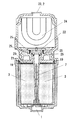
以下、本発明を添付図面に示す実施形態に基づいて説明する。図1には浄水カートリッジを模式的に表した側面断面図、図2には押さえ部材の斜視図、及びその部分拡大図、図3には浄水カートリッジの側面断面図を示すものである。
【0017】
浄水カートリッジは、外部ケーシングの内部に内部ケーシングを配設した構成を有するものである。外部ケーシングは有底筒状の外部ケーシング本体11と上記外部ケーシング本体11の開口を閉塞する外部ケーシング蓋体12とから構成されるものである。この外部ケーシング本体11と外部ケーシング蓋体12とは水密的に固定されている。外部ケーシング本体11の底部にはその中央部に外部ケーシング本体11を貫通して形成した流入口1を設けている。また、外部ケーシング蓋体12にはその中央部に外部ケーシング蓋体12を貫通して形成した流出口2を設けている。なお、上記流入口1及び流出口2とも外部ケーシングの外部方向に管状の立上り形状を有している。上記流入口1の位置する外部ケーシング本体11の底面の内面部分には外部ケーシング蓋体12方向に立上った水拡散部13が設けられている。この水拡散部13は、流入口1から外部ケーシング内に流入した水を上記水拡散部13に衝突させて外部ケーシング本体11の底面に沿わせて放射状に流すものである。
【0018】
上記外部ケーシング内に配置される内部ケーシングも、上記外部ケーシング同様に、有底筒状の内部ケーシング本体4と上記内部ケーシング本体4の開口を閉塞する内部ケーシング蓋体5とで構成されている。内部ケーシング本体4はその内部に微細粒子状の活性炭等で構成される吸着浄化材3を収納配置させるものであり、その筒側面に亘って透水性壁面部6を形成している。この透水性壁面部6は、流入口1から外部ケーシング内に流入した水を浄水カートリッジ内に導入させるものであると共に内部ケーシング本体4内に配置される吸着浄化材3の外方への漏れを防ぐものであり、不織布や網状のものや焼結体などから形成されている。具体的に、本例の内部ケーシング本体4は、筒側面に亘って網状壁を備えた筒状のかごで構成されている。つまり、透水性壁面部6は網状壁で構成されている。(図3)
上記内部ケーシング本体4の中央部には連通管7が設けられている。この連通管7は、始端を内部ケーシング本体4の底面部分に設けると共に終端を外部ケーシングの流出口2に位置させた直管状の管体であって、吸着浄化材3を通過した浄水を外部ケーシングの流出口2から吐出させるものである。また、この連通管7は、内部ケーシング内に位置する管側面のうち吸着浄化材3に隣接する位置に透水性壁面部6'を形成しているものである。この透水性壁面部6'は吸着浄化材3を通った浄水を連通管7内部に導入する部分である。具体的に本例では、連通管7は、内部ケーシング本体4の筒側面から内部ケーシング内部に導入された水をスムーズに連通管7に移動させることを図って、始端部分に行くにつれてその径が細くなるような形状に形成されており、また、この上記連通管7の始端部分は、内部ケーシング本体4の底面の中央部に設けた連通管嵌合凹所17に嵌合されている。(図3)
上記連通管7の透水性壁面部6'は内部ケーシング本体4の内部に位置すると共に、内部ケーシング本体4の透水性壁面部6と全面に亘って対向しているものであるが、この透水性壁面部6、6'の間の筒状空間に吸着浄化材3が収納される。ここで、吸着浄化材3は微粒子状の活性炭に限定されるものではなく、イオン交換樹脂やモルキュラーシーブやセラミックス、ミネラル鉱石などや二酸化チタン等の触媒などのいずれかまたは少なくとも2種類以上を混合したものを利用してもよいものである。
【0019】
上記内部ケーシング本体4の開口を閉塞するような内部ケーシング蓋体5とはかしめ等の加工作業で一体化されるものであるが、このとき、内部ケーシング蓋体5の中央部には連通管7が挿通され、また、上記内部ケーシング本体4の開口を閉塞した内部ケーシング蓋体5と吸着浄化材3との間には押さえ部材8が介在される。この押さえ部材8は、吸着浄化材3を含有してシート状に形成されたものである。具体的に、本例の押さえ部材8は、図2に示すように、粉末状活性炭からなる吸着浄化材3が添着されると共に弾性を有した織布14で中心に中空部8aを有した円盤シート状に形成されたものである。詳述すると、上記押さえ部材8は、通常の状態(内部ケーシング本体4に圧入されていない状態)では、その外径は内部ケーシング本体4の開口よりも大きい径を有すると共に、その厚みは約3mm程の厚みを有して形成されている。内部ケーシング本体4の開口を内部ケーシング蓋体5により閉塞させた際に、この押さえ部材8をその中空部8aに連通管7を挿通させて内部ケーシング蓋体5と吸着浄化材3との間に介在させると、内部ケーシング蓋体5により、上記押さえ部材8は内部ケーシング本体4の開口内に圧入挿入され、内部ケーシング蓋体5と吸着浄化材3との間で弾性変形をし(押さえ部材8の厚みは通常の状態の半分の厚みになる程に圧縮される)、吸着浄化材3を内部ケーシング本体4の底面に一様に押し付けて固定させることができるものである。後述するが、この押さえ部材8は、上述した吸着浄化材3を押さえつける目的の他に、浄水カートリッジ内部で吸着浄化材3を通過しないような水も浄化させる目的があり、適度な透水性と吸着浄化材3の含有を必要とする。しかして、押さえ部材8は適度な弾性と透水性及び吸着浄化材3の含有を備えていればいいものである。
【0020】
上述した内部ケーシングは外部ケーシングの内部に配置されるものであるが、このときには、内部ケーシング本体4の底面外面は外部ケーシング本体11の水拡散部13に当接され、対向する内部ケーシング本体4の底面外面と外部ケーシング本体11の底面内面、また、内部ケーシング本体4の筒側面外面と外部ケーシング本体11の筒側面内面、との間には隙間16が形成される。なお、内部ケーシング蓋体5から突出した連通管7の先端は外部ケーシングの流出口2に臨むものである。更に言うと、模式図である図1には表われていないが、内部ケーシング蓋体5は外部ケーシング蓋体12及び連通管7とパッキン25を介した水密保持構造を有している。(図3)
以下、上記浄水カートリッジにおける水の流れを示す。外部ケーシングの流入口1より外部ケーシング内に導入された水は、水拡散部13により外部ケーシング本体11の底面に沿って放射線状に拡散されると共に上記隙間16に流れるものであり、上記隙間16に流れる水のうちその大部分は、透水性壁面部6を通過して内部ケーシング内部に導入され、透水性壁面部6から吸着浄化材3を通過して浄水されるものである。そして上記浄水は透水性壁面部6'から連通管7に導入され、連通管7を通過して連通管7の出口、すなわち外部ケーシングの流出口2から吐出されるものである。ここで、上記隙間16に流れる水のうちその一部は、内部ケーシング本体4と内部ケーシング蓋体5との間から内部ケーシング内部に導入されるものであるが、この水も吸着浄化材3または押さえ部材8を通過して浄水されるものである。そして、上記浄水も透水性壁面部6'から連通管7に導入され、外部ケーシングの流出口2から吐出されるものである。すなわち、外部ケーシングの流入口1より外部ケーシング内に流入した水は、吸着浄化材3または吸着浄化材3が含有された押さえ部材8を通って全ての水が浄水になるものであって、外部ケーシングの流出口2から全て浄水として吐出されるものである。つまり、この浄水カートリッジでは、内部ケーシング蓋体5に沿わせて配置した押さえ部材8に吸着浄化材3を含有させていることから、いわゆるショートパスあるいはチャンネリングと呼ばれる現象は生じないものである。
【0021】
上述したように本例の浄水カートリッジでは、内部ケーシング本体4と内部ケーシング蓋体5との間から内部ケーシング本体4内部に流入する水も浄化できるものなので、ショートパスあるいはチャンネリングを防止する意味で従来の浄水カートリッジに設けられていた内部ケーシング本体4と内部ケーシング蓋体5との水密保持構造なるものは本例の浄水カートリッジには備えなくて済むものである。上記水密保持構造を備えないことで本例の浄水カートリッジは、従来の浄水カートリッジに比べて、浄水カートリッジの構造を簡易化することができるものであり、また、浄水カートリッジの容積のうち上記水密保持構造が占めていた容積分余計に吸着浄化材3を内部ケーシング本体4内に詰めることができるものである。更に、内部ケーシング本体4内に詰めた吸着浄化材3を押さえる押さえ部材8においても上記吸着浄化材3を含有させて形成したことから、従来の浄水カートリッジに比べて、浄水カートリッジの容積に占める吸着浄化材3の割合を上げることができ、つまり、従来と比較して浄水カートリッジの大きさはそのままに浄水カートリッジの吸着浄化能力を向上させているものである。
【0022】
なお、連通管7の透水性壁面部6'は吸着浄化材3に隣接する位置、つまり、少なくとも内部ケーシング蓋体5や押さえ部材8よりも内部ケーシング本体4の底面方向に近い位置において形成されていることから、上記内部ケーシング蓋体5を内部ケーシング本体4と同様に網状壁で形成させてもよく、つまり、内部ケーシング蓋体5に透水性壁面部6を設けてもよいものである。これによると内部ケーシング蓋体5部分からも内部ケーシング本体4内に水が導入されるようになるが、上記水は押さえ部材8を通過して連通管7の透水壁面部6'に至ることから、浄水カートリッジに流入した水は全て浄水にされて流出口2から吐出され、浄水カートリッジの本来的な浄水機能は確保されるのである。
【0023】
また、先の実施の形態の例の項で先述したように、押さえ部材8は適度な透水性を有すると共に、少なくとも内部ケーシング蓋体5と吸着浄化材3との対向方向、つまり、シート状に形成した押さえ部材8の厚さ方向に適度な弾性を有し、また、吸着浄化材3を含有したものであればよいものであり、押さえ部材8により多くの吸着浄化材3を含有させて浄水カートリッジの吸着浄化能力を向上させることを期して、以下の本発明の実施の形態の他例に列挙する押さえ部材8を先の実施の形態の例における押さえ部材8の代わりに用いてもよいものである。
【0024】
図4には、ポリウレタンなどの樹脂で連続気泡を有したスポンジ状の弾性多孔体10の内部に吸着浄化材3を添着させて形成した押さえ部材8を示す。これは、弾性多孔体10によって押さえ部材8には透水性及び弾性が備えらえ、更に上記弾性多孔体10の内部に吸着浄化材3を添着したことで弾性多孔体10に吸着浄化材3を含有させるものであり、弾性多孔体10、つまり押さえ部材8の内部を通過する水を浄化させるようにしたものである。ここで、弾性多孔体10としては樹脂製スポンジでなくても金属や繊維を綿状に形成したものでも好ましい。
【0025】
また、上記弾性多孔体10に替えて弾性を有した不織布9を用い、上記不織布9に吸着浄化材3を混入させて押さえ部材8を形成したものも好ましい。これも、弾性多孔体10同様に不織布9によって押さえ部材8には弾性及び透水性が備えられ、上記不織布9に吸着浄化材3を混入させて吸着浄化材3を含有するものであり、不織布9、つまり押さえ部材8の内部を通過する水を浄化させるようにしたものである。なお、弾性を有すると共に吸着浄化材3を混入させた不織布9として、活性炭素繊維で形成した不織布9を用いることも好ましい。これによると活性炭素繊維で不織布9を形成したことでより多くの活性炭(吸着浄化材3)を押さえ部材8に含有させることができるのである。
【0026】
図5には、弾性多孔体10の層と吸着浄化材3の層とを積層配置して形成した押さえ部材8を示す。ここで、吸着浄化材3の層は粒状、粉状または繊維状の活性炭で形成したものである。これも、上記弾性多孔体10によって押さえ部材8には透水性及び弾性が備えられるものであり、吸着浄化材3の層により押さえ部材8の内部を通過する水を浄化させるようにしたものであって、更に言うと、弾性多孔体10の層と吸着浄化材3の層とを積層配置したことはあらかじめ弾性多孔体10と吸着浄化材3を密着させて形成することになり、また、上記押さえ部材8の吸着浄化材3は内部ケーシング本体4に配置した吸着浄化材3となじみ易いものであることから、押さえ部材8と吸着浄化材3との間のわずかな隙間におけるろ過効率が悪い部分が生じるのを防ぐものであり、浄水カートリッジの吸着浄化能力の向上が実現可能となるものである。
【0027】
【発明の効果】
上記のように本発明の請求項1記載の浄水カートリッジにあっては、叙述したように、内部ケーシング本体の開口を閉塞した内部ケーシング蓋体と吸着浄化材との間に上記吸着浄化材を固定する押さえ部材を介在させると共に、上記押さえ部材が吸着浄化材を含有してシート状に形成されたので、内部ケーシング本体と内部ケーシング蓋体との間から内部ケーシング内に流入した水も、上記押さえ部材を介して浄水となって連通管に至るものであって、つまり、浄水カートリッジに流入させた水の全てが浄水されて流出口から吐出されるといった浄水カートリッジの本来の機能も確保できるものであり、また、これによって本願の浄水カートリッジは従来の浄水カートリッジにおける内部ケーシング本体と内部ケーシング蓋体との間にあった水密保持構造を備えなくて済むものであり、上記水密保持構造を備えないことで、浄水カートリッジの構造を簡易化することができると共に浄水カートリッジの容積のうち上記水密保持構造が占めていた容積分余計に吸着浄化材を内部ケーシング本体内に詰めることができて浄水カートリッジの容積に占める吸着浄化材の割合を上げることができ、つまり、従来と比較して浄水カートリッジの大きさはそのままに浄水カートリッジの吸着浄化能力を向上させることができるものである。更に言うと、押さえ部材にも吸着浄化材を含有させていることは、浄水カートリッジ内の吸着浄化材の占める割合の向上に資するものであって、浄水カートリッジの吸着浄化能力の向上が図られているものである。
【0028】
また、本発明の請求項2記載の浄水カートリッジにあっては、請求項1の効果に加えて、上記押さえ部材が、少なくとも内部ケーシング蓋体と吸着浄化材との対向方向に弾性を有してなるので、内部ケーシング蓋体が内部ケーシング本体の開口を閉塞した際に、内部ケーシング本体に配置した吸着浄化材と内部ケーシング蓋体との間で上記押さえ部材が圧縮されて弾性変形をし、上記弾性変形をして吸着浄化材に略隙間無く当接した押さえ部材が内部ケーシング蓋体から受ける内部ケーシング本体の底面方向の荷重を吸着浄化材に略一様に作用させるものであって、つまり、吸着浄化材を漏れなく確実に内部ケーシング本体の底面方向に押し付けることができるものである。
【0029】
また、本発明の請求項3記載の浄水カートリッジにあっては、請求項2の効果に加えて、上記押さえ部材を不織布に吸着浄化材を混入させて形成したので、上記不織布によって押さえ部材には弾性及び透水性が備えられると共に、上記不織布に吸着浄化材を混入させたことでより多くの吸着浄化材を押さえ部材に含有することができ、ひいては、浄水カートリッジの容積のうち吸着浄化材の占める割合を向上させて浄水カートリッジの吸着浄化能力の向上を図ることができる。
【0030】
また、本発明の請求項4記載の浄水カートリッジにあっては、請求項2の効果に加えて、押さえ部材を活性炭素繊維で形成した不織布で構成したので、上記不織布によって押さえ部材には弾性及び透水性が備えられると共に、活性炭素繊維で不織布を形成させたことでより多くの活性炭(吸着浄化材)を押さえ部材に含有することができる。更に言うと、弾性体として活性炭そのものを使用することとなり、請求項3よりも大きく浄水カートリッジの吸着浄化能力の向上を図ることができる。
【0031】
また、本発明の請求項5記載の浄水カートリッジにあっては、請求項2の効果に加えて、押さえ部材を弾性多孔体と吸着浄化材とで形成したので、弾性多孔体によって押さえ部材には透水性及び弾性が備えられるものであり、上記押さえ部材を吸着浄化材で構成させたことで押さえ部材に吸着浄化材を含有することができ、ひいては、浄水カートリッジの容積のうち吸着浄化材の占める割合を向上させることができる。更に言うと、弾性体として弾性多孔体を用いたことで押さえ部材には大きな弾性が備えられるものであり、これによって内部ケーシング本体に配置した吸着浄化材をより強く圧縮することができ、上記吸着浄化材を密に充填させることで浄水カートリッジの吸着浄化能力の向上を図ることができる。
【0032】
また、本発明の請求項6記載の浄水カートリッジにあっては、請求項2の効果に加えて、押さえ部材を弾性多孔体で形成し、上記弾性多孔体の内部に吸着浄化材を添着したので、弾性多孔体によって押さえ部材には透水性及び弾性が備えられるものであり、更に上記弾性多孔体の内部に吸着浄化材を添着したことで弾性多孔体に吸着浄化材を含有することができ、ひいては、浄水カートリッジの容積のうち吸着浄化材の占める割合を向上させて浄水カートリッジの吸着浄化能力の向上を図ることができる。
【図面の簡単な説明】
【図1】本発明の実施の形態の例の浄水カートリッジを模式的に示す側面断面図である。
【図2】(a)は押さえ部材の斜視図であり、(b)は(a)のA部の部分拡大図である。
【図3】同上の浄水カートリッジの側面断面図である。
【図4】本発明の実施の形態の他例を示すもので、弾性多孔体(不織布)の内部に吸着浄化材を含有させてなる押さえ部材の斜視図である。
【図5】本発明の実施の形態の更に他例を示すもので、弾性多孔体と吸着浄化材とを積層配置してなる押さえ部材の斜視図である。
【図6】従来技術の浄水カートリッジを模式的に示す側面断面図である。
【図7】同上の浄水カートリッジの側面断面図である。
【図8】従来技術の他例の浄水カートリッジを示す側面断面図である。
【符号の説明】
1 流入口
2 流出口
3 吸着浄化材
4 内部ケーシング本体
5 内部ケーシング蓋体
6 透水性壁面部
7 連通管
8 押さえ部材
[0001]
BACKGROUND OF THE INVENTION
The present invention relates to a water purification cartridge that removes and purifies residual chlorine, trihalomethane, and the like contained in tap water, and further adjusts metal components such as minerals in water.
[0002]
[Prior art]
The tap water contains various components such as residual chlorine, that is, chlorinated by chlorine disinfection, and trihalomethane. When consumers use tap water, especially for drinking, they are dissatisfied or anxious about the above ingredients and other ingredients in terms of taste and health. Therefore, in general, a water purifier such as an alkaline ionized water generator equipped with a water purification cartridge equipped with an adsorption purification material made of activated carbon or the like and a filter material made of a hollow fiber membrane filter or the like is used, and purification is performed by the water purification cartridge. We use clean water for drinking.
[0003]
In this water purification cartridge, the superiority or inferiority of the filtration or purification ability is determined by the size and amount of the filter medium (adsorption purification material and filter material). For example, in order to remove trihalomethane and the like from tap water, a water purification cartridge containing the above-described adsorption purification material represented by activated carbon is used, but its removal capability is determined by the content of the adsorption purification material of the water purification cartridge. .
[0004]
In order to maintain the removal capacity of a water purifier such as an alkaline ionized water generator over a long period of time, generally, the water purification cartridge is replaced, a large water purification cartridge equipped with a large amount of adsorption purification material is used, or It has been considered to regenerate the adsorption purification material. Regenerating the adsorbent purification material is inefficient because it requires the use of water vapor and hot water, is inefficient, and is a large water purification cartridge with a large amount of adsorbent purification material inside. Is inefficient because it reduces the flow rate that flows through the water purification cartridge due to friction loss in the filtration part of the water purification cartridge, and frequent replacement of the water purification cartridge wastes the adsorbent purification material and the water purifier. In order to increase the economic burden on the user, a water purifier equipped with an appropriate amount of adsorbent purification material and a replaceable water purification cartridge has been put into practical use.
[0005]
Examples of the water purification cartridge installed in the water purifier such as the alkaline ionized water generator include those shown in FIGS. 6 and 7. In this water purification cartridge, a bottomed cylindrical outer casing body 11 and an outer casing lid body 12 that closes an opening of the outer casing body 11 constitute an outer casing, and the inner casing that houses the adsorption purification material 3 is used as the outer casing. It is arranged inside the casing. An inflow port 1 for allowing water to flow into the outer casing is provided on the bottom surface of the outer casing body 11, and an outflow port 2 for discharging purified water is provided at the center of the outer casing lid 12. . Similarly to the outer casing, the inner casing is composed of a bottomed cylindrical inner casing body 4 and an inner casing lid 5 that closes the opening of the inner casing body 4. A water permeable wall portion 6 through which water flowing in from the inlet 1 of the casing can be introduced into the inner casing is formed, and a cylindrical adsorption purification is performed inside the inner casing body 4 along the water permeable wall portion 6. The material 3 is arranged. A communication pipe 7 is provided inside the cylinder of the adsorbing purification material 3 so as to penetrate the center of the inner casing lid 5 and have a terminal end positioned at the outlet 2 of the outer casing. The communication pipe 7 is connected to the inner casing lid 5 and the outer casing lid 12 with a watertight holding structure via a packing 25 at the end portion. That is, the communication pipe 7 has a function of bringing the purified water that has passed through the adsorption purification material 3 to the outlet 2 of the outer casing. In addition, an elastic plate 20 and a pressing plate 21 are interposed between the inner casing lid 5 and the adsorption purification material 3 that close the opening of the inner casing body 4. The elastic plate 20 and the pressing plate 21 are fixed by pressing the adsorption purification material 3 against the bottom surface of the inner casing body 4 by the inner casing lid 5. An O-ring 19 is interposed between the inner casing body 4 and the inner casing lid 5. The O-ring 19 forms a watertight holding structure between the inner casing body 4 and the inner casing lid 5, and the watertight holding structure allows the communication pipe to pass through the adsorption purification material 3 in the inner casing. 7, the outlet 2 is reached, and the water flowing into the water purification cartridge is discharged without being purified (referred to as short pass or channeling). In other words, all the water that has flowed into the outer casing from the inlet 1 is introduced into the inner casing through the water permeable wall portion 6, and is purified through the adsorption purification material 3 and passes through the communication pipe 7. The outlet 2 is discharged out of the outer casing.
[0006]
In addition, as shown in FIG. 8, the 2nd water purification cartridge which accommodated the filtering material 24 which consists of a hollow fiber membrane filter etc. in the water purification cartridge (henceforth 1st water purification cartridge) which accommodated the adsorption purification material 3 which consists of activated carbon etc. mentioned above. There is also a water purification cartridge in which the water that has passed through the adsorption purification material 3 of the first water purification cartridge can be supplied with a higher degree of water through the filter medium 24 of the second water purification cartridge.
[0007]
[Problems to be solved by the invention]
By the way, in the said water purification cartridge, when there was no watertight holding structure formed by the O-ring 19 between the inner casing lid 5 and the inner casing body 4, it flowed into the outer casing from the inlet 1 of the outer casing. Part of the water flows into the inner casing from between the inner casing lid 5 and the inner casing body 4 and reaches the communication pipe 7 without passing through the adsorption purification material 3 and is discharged from the outlet 2 of the outer casing. That is, a short pass or channeling occurs, and the quality of the purified water produced by the purified water cartridge is lowered.
[0008]
Thus, the watertight holding structure between the inner casing lid 5 and the inner casing body 4 is a necessary structure in the water purification cartridge having the above structure, but between the inner casing lid 5 and the inner casing body 4. The watertight holding structure of the water occupies a relatively large proportion of the volume of the water purification cartridge, and accordingly, the proportion of the adsorption purification material 3 occupying the volume of the water purification cartridge is reduced, and the filtration capacity of the water purification cartridge (adsorption) Purification ability).
[0009]
The present invention has been made in view of the above-mentioned reasons. Even in the case of a water purification cartridge having the same size as the conventional one, the ratio of the adsorption purification material to the volume of the water purification cartridge is increased and the filtration capacity (adsorption purification) is increased. It is an object of the present invention to provide a water purification cartridge capable of increasing the capability).
[0010]
[Means for Solving the Problems]
In order to solve the above problems, in the water purification cartridge according to claim 1 of the present invention, an inner casing is disposed inside an outer casing provided with an inlet 1 and an outlet 2, and the inner casing is adsorbed and purified. A bottomed cylindrical inner casing body 4 containing the material 3 therein and an inner casing lid body 5 for closing the opening of the inner casing body 4 and flowing into the outer casing from the inlet 1 of the outer casing A water-permeable wall portion 6 for introducing the water into the inner casing body 4 is provided at least on the cylindrical side surface portion of the inner casing body 5, and the purified water purified through the adsorption purification material 3 inside the inner casing body 4 is removed from the outer casing. An internal casing lid provided with a communication pipe 7 extending through the inner casing lid 5 to close the opening of the inner casing body 4. A pressing member 8 for fixing the adsorption purification material 3 is interposed between the adsorption purification material 3 and the adsorption purification material 3, and the pressing member 8 is formed in a sheet shape containing the adsorption purification material 3. . Thereby, the water that has flowed into the inner casing from between the inner casing body 4 and the inner casing lid 5 also becomes purified water through the pressing member 8 that contains the adsorption purification material 3 and is formed into a sheet shape. It leads to the communication pipe 7, that is, it can secure the original function of the water purification cartridge such that all of the water that has flowed into the water purification cartridge is purified and discharged from the outlet 2. The water purification cartridge of the present invention is not required to have the watertight holding structure between the inner casing body 4 and the inner casing lid 5 of the conventional water purification cartridge, and by not having the watertight holding structure, In addition to simplifying the structure, adsorption and purification is performed on the extra volume occupied by the watertight holding structure in the volume of the water purification cartridge. 3 can be packed in the inner casing body 4 to increase the ratio of the adsorption purification material 3 to the volume of the water purification cartridge, that is, the adsorption of the water purification cartridge as it is compared with the conventional size. The purification ability can be improved. Furthermore, the fact that the adsorbing / purifying material 3 is also contained in the pressing member 8 contributes to an improvement in the proportion of the adsorbing / purifying material 3 in the water purification cartridge, and the adsorbing / purifying capacity is improved. It is.
[0011]
Moreover, in the water purification cartridge which concerns on Claim 2 of this invention, the said pressing member 8 has elasticity in the opposing direction of the internal casing cover body 5 and the adsorption | suction purification material 3 in Claim 1. It is characterized by that. Thereby, when the inner casing lid 5 closes the opening of the inner casing main body 4, the pressing member 8 is compressed between the adsorption purification material 3 disposed on the inner casing main body 4 and the inner casing lid 5. The load in the bottom direction of the inner casing main body 4 received from the inner casing lid 5 by the pressing member 8 that has elastically deformed and is in contact with the adsorbing purification material 3 with substantially no gap is substantially equal to the adsorption purification material 3. That is, the adsorption purification material 3 can be reliably pressed toward the bottom surface of the inner casing body 4 without leakage.
[0012]
Moreover, in the water purification cartridge which concerns on Claim 3 of this invention, in Claim 2, the said pressing member 8 was formed by mixing the adsorption purification material 3 in the nonwoven fabric 9, It is characterized by the above-mentioned. Accordingly, the pressing member 8 is provided with elasticity and water permeability by the nonwoven fabric 9, and more adsorbing purification material 3 can be contained in the pressing member 8 by mixing the adsorption purification material 3 into the nonwoven fabric 9. As a result, the proportion of the adsorbing purification material 3 in the volume of the water purification cartridge can be improved.
[0013]
The water purification cartridge according to claim 4 of the present invention is characterized in that, in claim 2, the pressing member 8 is composed of a nonwoven fabric 9 formed of activated carbon fibers. Accordingly, the pressing member 8 is provided with elasticity and water permeability by the non-woven fabric 9, and contains more activated carbon (adsorption purification material 3) in the pressing member 8 by forming the non-woven fabric 9 with activated carbon fibers. As a result, the proportion of the adsorbing purification material 3 in the volume of the water purification cartridge can be improved.
[0014]
The water purification cartridge according to claim 5 of the present invention is characterized in that, in claim 2, the pressing member 8 is formed of the elastic porous body 10 and the adsorption purification material 3. Thereby, the holding member 8 is provided with water permeability and elasticity by the elastic porous body 10, and the holding member 8 contains the adsorption purification material 3 by configuring the holding member 8 with the adsorption purification material 3. As a result, the proportion of the adsorbing purification material 3 in the volume of the water purification cartridge can be improved.
[0015]
Further, in the water purification cartridge according to claim 6 of the present invention, in claim 2, the pressing member 8 is formed of the elastic porous body 10, and the adsorption purification material 3 is attached to the inside of the elastic porous body 10. It is characterized by. Thereby, the holding member 8 is provided with water permeability and elasticity by the elastic porous body 10, and the adsorbing purification material 3 is further attached to the inside of the elastic porous body 10, so that the adsorbing purification material 3 is attached to the holding member 8. As a result, the proportion of the adsorbing purification material 3 in the volume of the water purification cartridge can be improved.
[0016]
DETAILED DESCRIPTION OF THE INVENTION
Hereinafter, the present invention will be described based on embodiments shown in the accompanying drawings. FIG. 1 is a side sectional view schematically showing a water purification cartridge, FIG. 2 is a perspective view of a pressing member, and a partially enlarged view thereof, and FIG. 3 is a side sectional view of the water purification cartridge.
[0017]
The water purification cartridge has a configuration in which an inner casing is disposed inside an outer casing. The outer casing includes a bottomed cylindrical outer casing body 11 and an outer casing lid body 12 that closes the opening of the outer casing body 11. The outer casing body 11 and the outer casing lid 12 are fixed in a watertight manner. An inflow port 1 formed through the outer casing main body 11 is provided at the center of the bottom of the outer casing main body 11. Further, the outer casing lid 12 is provided with an outlet 2 formed through the outer casing lid 12 at the center thereof. Note that both the inlet 1 and the outlet 2 have a tubular rising shape toward the outside of the outer casing. A water diffusion portion 13 rising in the direction of the outer casing lid 12 is provided on the inner surface portion of the bottom surface of the outer casing body 11 where the inlet 1 is located. The water diffusion portion 13 causes water that has flowed into the outer casing from the inlet 1 to collide with the water diffusion portion 13 and flow radially along the bottom surface of the outer casing body 11.
[0018]
The inner casing disposed in the outer casing is also composed of a bottomed cylindrical inner casing body 4 and an inner casing lid 5 that closes the opening of the inner casing body 4 in the same manner as the outer casing. The inner casing body 4 accommodates and disposes the adsorption purification material 3 composed of fine particulate activated carbon or the like, and forms a water permeable wall portion 6 over the cylinder side surface. The water permeable wall portion 6 introduces water that has flowed into the outer casing from the inlet 1 into the water purification cartridge and prevents leakage of the adsorbent purification material 3 disposed in the inner casing body 4 to the outside. It is for preventing, and is formed from a nonwoven fabric, a net-like thing, a sintered compact, etc. Specifically, the inner casing body 4 of the present example is formed of a cylindrical car provided with a mesh wall over the cylinder side surface. That is, the water permeable wall surface part 6 is comprised by the net-like wall. (Figure 3)
A communication pipe 7 is provided at the center of the inner casing body 4. The communication pipe 7 is a straight tubular body having a start end provided on the bottom surface portion of the inner casing body 4 and a terminal end positioned at the outlet 2 of the outer casing, and the purified water that has passed through the adsorption purification material 3 is supplied to the outer casing. It discharges from the outflow port 2. In addition, the communication pipe 7 is formed with a water permeable wall portion 6 ′ at a position adjacent to the adsorption purification material 3 on the side surface of the pipe located in the inner casing. This water-permeable wall surface portion 6 ′ is a portion that introduces purified water that has passed through the adsorption purification material 3 into the communication pipe 7. Specifically, in this example, the communication pipe 7 is designed to smoothly move water introduced into the inner casing from the cylindrical side surface of the inner casing body 4 to the communication pipe 7, and the diameter of the communication pipe 7 increases toward the start end portion. It is formed in a shape that becomes thinner, and the starting end portion of the communication pipe 7 is fitted in a communication pipe fitting recess 17 provided at the center of the bottom surface of the inner casing body 4. (Figure 3)
The water permeable wall portion 6 ′ of the communication pipe 7 is located inside the inner casing body 4 and faces the water permeable wall portion 6 of the inner casing body 4 over the entire surface. The adsorption purification material 3 is accommodated in the cylindrical space between the wall surface parts 6 and 6 '. Here, the adsorption purification material 3 is not limited to particulate activated carbon, and any one or at least two kinds of catalysts such as ion exchange resins, molecular sieves, ceramics, mineral ores, and titanium dioxide are mixed. You may use what you did.
[0019]
The inner casing lid body 5 that closes the opening of the inner casing body 4 is integrated by processing such as caulking. At this time, the communication pipe 7 is connected to the central portion of the inner casing lid body 5. Further, a pressing member 8 is interposed between the inner casing lid 5 and the adsorption purification material 3 that close the opening of the inner casing body 4. The pressing member 8 includes the adsorption purification material 3 and is formed in a sheet shape. Specifically, as shown in FIG. 2, the pressing member 8 of the present example is a disk having a hollow portion 8a in the center with a woven cloth 14 having an adsorbing purification material 3 made of powdered activated carbon attached thereto and having elasticity. It is formed in a sheet shape. More specifically, the pressing member 8 has an outer diameter larger than that of the opening of the inner casing body 4 and a thickness of about 3 mm in a normal state (a state where the pressing member 8 is not press-fitted into the inner casing body 4). It is formed with a thickness of about. When the opening of the inner casing body 4 is closed by the inner casing lid body 5, the holding member 8 is inserted into the hollow portion 8 a of the communication pipe 7 so that the inner casing lid body 5 and the adsorption purification material 3 are interposed between them. When interposed, the pressing member 8 is press-fitted into the opening of the inner casing body 4 by the inner casing lid 5 and elastically deformed between the inner casing lid 5 and the adsorption purification material 3 (the pressing member 8). The adsorption purification material 3 can be uniformly pressed against the bottom surface of the inner casing body 4 and fixed. As will be described later, the pressing member 8 has the purpose of purifying water that does not pass through the adsorption purification material 3 inside the water purification cartridge in addition to the purpose of pressing the adsorption purification material 3 described above. The inclusion of the purification material 3 is required. Therefore, the pressing member 8 only needs to have appropriate elasticity, water permeability, and adsorption purification material 3.
[0020]
The inner casing described above is disposed inside the outer casing. At this time, the outer surface of the bottom surface of the inner casing body 4 is brought into contact with the water diffusion portion 13 of the outer casing body 11 and A gap 16 is formed between the outer surface of the bottom surface and the inner surface of the bottom surface of the outer casing body 11, and the outer surface of the cylinder side surface of the inner casing body 4 and the inner surface of the cylinder side surface of the outer casing body 11. The tip of the communication pipe 7 protruding from the inner casing lid 5 faces the outlet 2 of the outer casing. Furthermore, although not shown in FIG. 1, which is a schematic diagram, the inner casing lid 5 has a watertight holding structure through the outer casing lid 12, the communication pipe 7 and the packing 25. (Figure 3)
Hereinafter, the flow of water in the water purification cartridge will be described. The water introduced into the outer casing from the inlet 1 of the outer casing is diffused radially along the bottom surface of the outer casing body 11 by the water diffusion portion 13 and flows into the gap 16. Most of the water flowing in the water passes through the water permeable wall surface portion 6 and is introduced into the inner casing, and passes through the adsorption purification material 3 from the water permeable wall surface portion 6 to be purified. And the said purified water is introduce | transduced into the communicating pipe 7 from the water-permeable wall part 6 ', passes through the communicating pipe 7, and is discharged from the exit of the communicating pipe 7, ie, the outflow port 2 of an external casing. Here, a part of the water flowing in the gap 16 is introduced into the inner casing from between the inner casing body 4 and the inner casing lid body 5. The water passes through the pressing member 8 and is purified. And the said purified water is also introduce | transduced into the communicating pipe 7 from the water-permeable wall part 6 ', and is discharged from the outflow port 2 of an outer casing. That is, the water that has flowed into the outer casing from the inlet 1 of the outer casing passes through the adsorption purification material 3 or the pressing member 8 containing the adsorption purification material 3, and all the water becomes purified water. All are discharged as purified water from the outlet 2 of the casing. That is, in this water purification cartridge, since the adsorbing purification material 3 is contained in the pressing member 8 disposed along the inner casing lid body 5, a phenomenon called so-called short path or channeling does not occur.
[0021]
As described above, in the water purification cartridge of this example, water flowing into the inner casing body 4 from between the inner casing body 4 and the inner casing lid body 5 can be purified, and therefore, in the sense of preventing short paths or channeling. The water-tight holding structure of the inner casing main body 4 and the inner casing lid 5 provided in the conventional water purification cartridge need not be provided in the water purification cartridge of this example. By not having the watertight holding structure, the water purification cartridge of this example can simplify the structure of the water purification cartridge as compared with the conventional water purification cartridge, and the watertight holding of the volume of the water purification cartridge is as follows. The adsorption purification material 3 can be packed into the inner casing body 4 in the extra volume occupied by the structure. Further, the holding member 8 for holding the adsorbing purification material 3 packed in the inner casing body 4 is also formed by containing the adsorbing purification material 3, so that the adsorption occupying the volume of the water purification cartridge as compared with the conventional water purification cartridge. The ratio of the purification material 3 can be increased, that is, the adsorption purification capacity of the water purification cartridge is improved while maintaining the size of the water purification cartridge as compared with the conventional case.
[0022]
The water-permeable wall surface portion 6 ′ of the communication pipe 7 is formed at a position adjacent to the adsorption purification material 3, that is, at a position closer to the bottom surface direction of the inner casing body 4 than at least the inner casing lid body 5 and the pressing member 8. Therefore, the inner casing lid 5 may be formed of a mesh wall in the same manner as the inner casing main body 4, that is, the inner casing lid 5 may be provided with the water permeable wall portion 6. According to this, water is introduced into the inner casing body 4 also from the inner casing lid 5 portion, but the water passes through the pressing member 8 and reaches the water permeable wall surface portion 6 ′ of the communication pipe 7. All of the water that has flowed into the water purification cartridge is purified and discharged from the outlet 2 to ensure the original water purification function of the water purification cartridge.
[0023]
Further, as described above in the section of the example of the previous embodiment, the pressing member 8 has appropriate water permeability and at least the facing direction of the inner casing lid 5 and the adsorption purification material 3, that is, in a sheet shape. The formed pressing member 8 has an appropriate elasticity in the thickness direction and needs only to contain the adsorption purification material 3. In order to improve the adsorption and purification capacity of the cartridge, the pressing member 8 listed in other examples of the embodiment of the present invention may be used instead of the pressing member 8 in the example of the previous embodiment. It is.
[0024]
FIG. 4 shows a pressing member 8 formed by adhering the adsorbing purification material 3 inside a sponge-like elastic porous body 10 having open cells made of resin such as polyurethane. This is because the holding member 8 is provided with water permeability and elasticity by the elastic porous body 10, and the adsorption purification material 3 is attached to the inside of the elastic porous body 10, so that the adsorption purification material 3 is attached to the elastic porous body 10. It is contained and purifies the elastic porous body 10, that is, the water passing through the inside of the pressing member 8. Here, the elastic porous body 10 is preferably not a resin sponge, but a metal or fiber formed in a cotton shape.
[0025]
It is also preferable to use a non-woven fabric 9 having elasticity instead of the elastic porous body 10 and forming the pressing member 8 by mixing the adsorbing purification material 3 into the non-woven fabric 9. Similarly to the elastic porous body 10, the pressing member 8 is provided with elasticity and water permeability by the nonwoven fabric 9, the adsorption purification material 3 is mixed into the nonwoven fabric 9 and contains the adsorption purification material 3. That is, the water passing through the inside of the pressing member 8 is purified. In addition, it is also preferable to use the nonwoven fabric 9 formed with activated carbon fibers as the nonwoven fabric 9 having elasticity and mixed with the adsorption purification material 3. According to this, more activated carbon (adsorption purification material 3) can be contained in the pressing member 8 by forming the nonwoven fabric 9 with activated carbon fibers.
[0026]
FIG. 5 shows a pressing member 8 formed by laminating and arranging a layer of the elastic porous body 10 and a layer of the adsorption purification material 3. Here, the layer of the adsorption purification material 3 is formed of granular, powdery or fibrous activated carbon. This is also because the holding member 8 is provided with water permeability and elasticity by the elastic porous body 10, and the water passing through the inside of the holding member 8 is purified by the layer of the adsorption purification material 3. More specifically, the arrangement of the elastic porous body 10 layer and the adsorption purification material 3 layer is formed by adhering the elastic porous body 10 and the adsorption purification material 3 in advance. Since the adsorption purification material 3 of the member 8 is easily compatible with the adsorption purification material 3 disposed in the inner casing body 4, there is a portion with poor filtration efficiency in a slight gap between the pressing member 8 and the adsorption purification material 3. It is possible to prevent the occurrence and to improve the adsorption purification capacity of the water purification cartridge.
[0027]
【The invention's effect】
As described above, in the water purification cartridge according to claim 1 of the present invention, the adsorbing purification material is fixed between the inner casing lid body and the adsorbing purification material which closes the opening of the inner casing body. Since the pressing member is interposed between the inner casing body and the inner casing lid body, the water flowing into the inner casing is also suppressed by the pressing member. It becomes purified water through the member and reaches the communication pipe, that is, it can secure the original function of the purified water cartridge, that is, all the water flowing into the purified water cartridge is purified and discharged from the outlet. And the water purification cartridge of the present application is located between the inner casing body and the inner casing lid in the conventional water purification cartridge. It is not necessary to provide a dense holding structure, and by not providing the watertight holding structure, the structure of the water purification cartridge can be simplified, and the volume occupied by the watertight holding structure in the volume of the water purification cartridge can be reduced. Extra adsorption purification material can be packed in the inner casing body, and the proportion of adsorption purification material in the volume of the water purification cartridge can be increased. It is possible to improve the adsorption / purification ability. Furthermore, the fact that the holding member also contains an adsorption purification material contributes to an increase in the proportion of the adsorption purification material in the water purification cartridge, and improves the adsorption purification capacity of the water purification cartridge. It is what.
[0028]
Further, in the water purification cartridge according to claim 2 of the present invention, in addition to the effect of claim 1, the pressing member has elasticity in the opposing direction of at least the inner casing lid and the adsorption purification material. Therefore, when the inner casing lid closes the opening of the inner casing main body, the pressing member is compressed and elastically deformed between the adsorption purification material disposed in the inner casing main body and the inner casing lid, The pressing member that is elastically deformed and comes into contact with the adsorbing purification material with almost no gap causes the load in the bottom direction of the inner casing body received from the inner casing lid to act on the adsorbing purification material substantially uniformly. The adsorbent purification material can be reliably pressed toward the bottom surface of the inner casing body without leakage.
[0029]
Moreover, in the water purification cartridge according to claim 3 of the present invention, in addition to the effect of claim 2, the pressing member is formed by mixing the adsorbing purification material into the nonwoven fabric. It is provided with elasticity and water permeability, and more adsorbing purification material can be contained in the pressing member by mixing the adsorbing purification material into the nonwoven fabric. As a result, the adsorption purification material occupies the volume of the water purification cartridge. It is possible to improve the adsorption purification capacity of the water purification cartridge by increasing the ratio.
[0030]
Further, in the water purification cartridge according to claim 4 of the present invention, in addition to the effect of claim 2, the pressing member is made of a nonwoven fabric formed of activated carbon fiber, so that the pressing member is elastic and non-woven by the nonwoven fabric. While being provided with water permeability, more carbon (adsorption purification material) can be contained in the pressing member by forming a nonwoven fabric with activated carbon fibers. More specifically, activated carbon itself is used as the elastic body, and the adsorption purification capacity of the water purification cartridge can be improved more than in the third aspect.
[0031]
Further, in the water purification cartridge according to claim 5 of the present invention, in addition to the effect of claim 2, the pressing member is formed of the elastic porous body and the adsorption purification material. It is provided with water permeability and elasticity, and the pressing member can be made of an adsorption purification material, so that the adsorption member can be contained in the holding member. As a result, the adsorption purification material occupies the volume of the water purification cartridge. The ratio can be improved. Furthermore, by using an elastic porous body as the elastic body, the holding member is provided with a large elasticity, and thereby, the adsorption purification material arranged in the inner casing body can be more strongly compressed, and the adsorption The adsorption purification capacity of the water purification cartridge can be improved by densely filling the purification material.
[0032]
In the water purification cartridge according to claim 6 of the present invention, in addition to the effect of claim 2, the pressing member is formed of an elastic porous body, and the adsorbing purification material is attached to the inside of the elastic porous body. Further, the holding member is provided with water permeability and elasticity by the elastic porous body, and further, an adsorption purification material can be contained in the elastic porous body by attaching an adsorption purification material to the inside of the elastic porous body, As a result, it is possible to improve the adsorption purification capacity of the water purification cartridge by increasing the ratio of the adsorption purification material in the volume of the water purification cartridge.
[Brief description of the drawings]
FIG. 1 is a side cross-sectional view schematically showing a water purification cartridge according to an example of an embodiment of the present invention.
2A is a perspective view of a pressing member, and FIG. 2B is a partially enlarged view of a portion A in FIG.
FIG. 3 is a side sectional view of the same water purification cartridge.
FIG. 4 shows another example of the embodiment of the present invention, and is a perspective view of a pressing member in which an adsorbing purification material is contained inside an elastic porous body (nonwoven fabric).
FIG. 5 shows still another example of the embodiment of the present invention, and is a perspective view of a pressing member formed by laminating an elastic porous body and an adsorption purification material.
FIG. 6 is a side cross-sectional view schematically showing a conventional water purification cartridge.
FIG. 7 is a side sectional view of the same water purification cartridge.
FIG. 8 is a side sectional view showing a water purification cartridge according to another example of the prior art.
[Explanation of symbols]
1 Inlet
2 outlet
3 Adsorbent purification material
4 Inner casing body
5 Inner casing lid
6 Water permeability wall surface
7 Communication pipe
8 Holding member

Claims (6)

流入口と流出口を設けた外部ケーシングの内部に内部ケーシングを配設し、上記内部ケーシングが吸着浄化材を内部に収納した有底筒状の内部ケーシング本体と上記内部ケーシング本体の開口を閉塞する内部ケーシング蓋体とを有し、上記外部ケーシングの流入口から外部ケーシング内に流入した水を内部ケーシング本体の内部に導入する透水性壁面部を上記内部ケーシング本体の少なくとも筒側面部分に設け、内部ケーシング本体内部の吸着浄化材を通って浄化した浄水を外部ケーシングの流出口に至らしめる連通管を上記内部ケーシング蓋体を貫通して設け、上記内部ケーシング本体の開口を閉塞した内部ケーシング蓋体と吸着浄化材との間に上記吸着浄化材を固定する押さえ部材を介在させると共に、上記押さえ部材が吸着浄化材を含有してシート状に形成されたことを特徴とする浄水カートリッジ。An inner casing is disposed inside an outer casing provided with an inflow port and an outflow port, and the inner casing closes the bottomed cylindrical inner casing body in which the adsorption purification material is housed and the opening of the inner casing body. An inner casing lid, and a water-permeable wall portion for introducing water that has flowed into the outer casing from the inlet of the outer casing into the inner casing body is provided at least on the cylindrical side surface of the inner casing body, An internal casing lid that is provided with a communication pipe that penetrates the inner casing lid to close the purified water that has passed through the adsorption purification material inside the casing main body to the outlet of the outer casing, and that closes the opening of the inner casing body; A holding member for fixing the adsorption purification material is interposed between the adsorption purification material and the holding member includes the adsorption purification material. Purification cartridge, characterized in that it is formed into a sheet by. 上記押さえ部材が、少なくとも内部ケーシング蓋体と吸着浄化材との対向方向に弾性を有してなることを特徴とする請求項1記載の浄水カートリッジ。2. The water purification cartridge according to claim 1, wherein the pressing member has elasticity in a direction opposite to at least the inner casing lid and the adsorption purification material. 上記押さえ部材を不織布に吸着浄化材を混入させて形成したことを特徴とする請求項2記載の浄水カートリッジ。3. The water purification cartridge according to claim 2, wherein the pressing member is formed by mixing an adsorbing purification material into a nonwoven fabric. 押さえ部材を活性炭素繊維で形成した不織布で構成したことを特徴とする請求項2記載の浄水カートリッジ。The water purification cartridge according to claim 2, wherein the pressing member is made of a nonwoven fabric formed of activated carbon fibers. 押さえ部材を弾性多孔体と吸着浄化材とで形成したことを特徴とする請求項2記載の浄水カートリッジ。The water purification cartridge according to claim 2, wherein the pressing member is formed of an elastic porous body and an adsorption purification material. 押さえ部材を弾性多孔体で形成し、上記弾性多孔体の内部に吸着浄化材を添着したことを特徴とする請求項2記載の浄水カートリッジ。The water purification cartridge according to claim 2, wherein the pressing member is formed of an elastic porous body, and an adsorption purification material is attached to the inside of the elastic porous body.
JP2002024625A 2001-01-31 2002-01-31 Water purification cartridge Expired - Fee Related JP3838112B2 (en)

Priority Applications (1)

Application Number Priority Date Filing Date Title
JP2002024625A JP3838112B2 (en) 2001-01-31 2002-01-31 Water purification cartridge

Applications Claiming Priority (3)

Application Number Priority Date Filing Date Title
JP2001024701 2001-01-31
JP2001-24701 2001-01-31
JP2002024625A JP3838112B2 (en) 2001-01-31 2002-01-31 Water purification cartridge

Publications (2)

Publication Number Publication Date
JP2002301471A JP2002301471A (en) 2002-10-15
JP3838112B2 true JP3838112B2 (en) 2006-10-25

Family

ID=26608711

Family Applications (1)

Application Number Title Priority Date Filing Date
JP2002024625A Expired - Fee Related JP3838112B2 (en) 2001-01-31 2002-01-31 Water purification cartridge

Country Status (1)

Country Link
JP (1) JP3838112B2 (en)

Families Citing this family (4)

* Cited by examiner, † Cited by third party
Publication number Priority date Publication date Assignee Title
JP4543965B2 (en) * 2005-03-02 2010-09-15 パナソニック電工株式会社 Water purification cartridge and water purification apparatus provided with the same
JP5804468B2 (en) * 2010-08-17 2015-11-04 ジョプラックス株式会社 Water purification cartridge, manufacturing method thereof, and water purifier
JP2013242235A (en) * 2012-05-21 2013-12-05 Shimizu Corp Contamination water treatment unit
JP6739975B2 (en) * 2016-04-18 2020-08-12 三菱ケミカル・クリンスイ株式会社 Water purification cartridge and water purifier

Also Published As

Publication number Publication date
JP2002301471A (en) 2002-10-15

Similar Documents

Publication Publication Date Title
CN102510836B (en) Water purifier
CA2432899C (en) Pitcher type water purifier and purification cartridge for the water purifier
CN205419962U (en) Water purifying filter cartridge
JP4799899B2 (en) Water purifier and kitchen where it was installed
JP3838112B2 (en) Water purification cartridge
JP5090593B2 (en) Water purification cartridge
CN103408078A (en) Water purifying cartridge, and water purifier
JP4747116B2 (en) Filtration cartridge and water purifier having the same
JP2009061352A (en) Water purification cartridge and water purifier
JP2005000768A (en) Water cleaning cartridge
JPH09248557A (en) Water purifier
JP3236640B2 (en) Water purifier
JP4674388B2 (en) Clean water shower
JP4441271B2 (en) Water purification cartridge and water purifier
JP2004000956A (en) Water purification cartridge having built-in tap
CN221028014U (en) Mineralized filter element
JP4117034B2 (en) Water purifier
JP3032555B2 (en) Water purifier
JPH0871542A (en) Water purifying cartridge
JP5601544B2 (en) A faucet equipped with a water purification cartridge
JP3209867B2 (en) Water purifier
KR102380908B1 (en) Filter Cartridge, Water Purifying Filter Assembly and Portable Water Purification Pail having the same
JP4182066B2 (en) Water purification cartridge and water purifier
JP4967187B2 (en) Water purification cartridge and water purifier
JP2003024723A (en) Filter material for water purifier containing titanium silicate and water purifier using the same

Legal Events

Date Code Title Description
A621 Written request for application examination

Free format text: JAPANESE INTERMEDIATE CODE: A621

Effective date: 20041119

A977 Report on retrieval

Free format text: JAPANESE INTERMEDIATE CODE: A971007

Effective date: 20060629

TRDD Decision of grant or rejection written
A01 Written decision to grant a patent or to grant a registration (utility model)

Free format text: JAPANESE INTERMEDIATE CODE: A01

Effective date: 20060711

A61 First payment of annual fees (during grant procedure)

Free format text: JAPANESE INTERMEDIATE CODE: A61

Effective date: 20060724

FPAY Renewal fee payment (event date is renewal date of database)

Free format text: PAYMENT UNTIL: 20090811

Year of fee payment: 3

S533 Written request for registration of change of name

Free format text: JAPANESE INTERMEDIATE CODE: R313533

FPAY Renewal fee payment (event date is renewal date of database)

Free format text: PAYMENT UNTIL: 20090811

Year of fee payment: 3

R350 Written notification of registration of transfer

Free format text: JAPANESE INTERMEDIATE CODE: R350

FPAY Renewal fee payment (event date is renewal date of database)

Free format text: PAYMENT UNTIL: 20090811

Year of fee payment: 3

FPAY Renewal fee payment (event date is renewal date of database)

Free format text: PAYMENT UNTIL: 20100811

Year of fee payment: 4

FPAY Renewal fee payment (event date is renewal date of database)

Free format text: PAYMENT UNTIL: 20110811

Year of fee payment: 5

FPAY Renewal fee payment (event date is renewal date of database)

Free format text: PAYMENT UNTIL: 20120811

Year of fee payment: 6

LAPS Cancellation because of no payment of annual fees