JP3845745B2 - GAME MACHINE, AND GAME MACHINE CONTROL METHOD - Google Patents
GAME MACHINE, AND GAME MACHINE CONTROL METHOD Download PDFInfo
- Publication number
- JP3845745B2 JP3845745B2 JP3385998A JP3385998A JP3845745B2 JP 3845745 B2 JP3845745 B2 JP 3845745B2 JP 3385998 A JP3385998 A JP 3385998A JP 3385998 A JP3385998 A JP 3385998A JP 3845745 B2 JP3845745 B2 JP 3845745B2
- Authority
- JP
- Japan
- Prior art keywords
- game
- external storage
- cassette
- information
- storage devices
- Prior art date
- Legal status (The legal status is an assumption and is not a legal conclusion. Google has not performed a legal analysis and makes no representation as to the accuracy of the status listed.)
- Expired - Fee Related
Links
- 238000000034 method Methods 0.000 title claims description 13
- 230000000694 effects Effects 0.000 claims description 10
- 238000010586 diagram Methods 0.000 description 9
- 230000008901 benefit Effects 0.000 description 3
- 239000000284 extract Substances 0.000 description 3
- 239000000758 substrate Substances 0.000 description 3
- 230000015572 biosynthetic process Effects 0.000 description 2
- 230000008859 change Effects 0.000 description 2
- 239000002131 composite material Substances 0.000 description 2
- 238000007639 printing Methods 0.000 description 2
- 238000012545 processing Methods 0.000 description 2
- 238000003786 synthesis reaction Methods 0.000 description 2
- NIXOWILDQLNWCW-UHFFFAOYSA-N acrylic acid group Chemical group C(C=C)(=O)O NIXOWILDQLNWCW-UHFFFAOYSA-N 0.000 description 1
- 238000005516 engineering process Methods 0.000 description 1
- 230000006870 function Effects 0.000 description 1
- 230000006872 improvement Effects 0.000 description 1
- 238000003780 insertion Methods 0.000 description 1
- 230000037431 insertion Effects 0.000 description 1
- 238000009434 installation Methods 0.000 description 1
- 238000004519 manufacturing process Methods 0.000 description 1
- 230000004048 modification Effects 0.000 description 1
- 238000012986 modification Methods 0.000 description 1
- 230000008569 process Effects 0.000 description 1
- 230000004044 response Effects 0.000 description 1
- 238000012552 review Methods 0.000 description 1
- 238000000859 sublimation Methods 0.000 description 1
- 230000008022 sublimation Effects 0.000 description 1
- 230000002194 synthesizing effect Effects 0.000 description 1
- 238000007651 thermal printing Methods 0.000 description 1
Images


Landscapes
- Closed-Circuit Television Systems (AREA)
- Controls And Circuits For Display Device (AREA)
- User Interface Of Digital Computer (AREA)
Description
【0001】
【発明の属する技術分野】
本発明は、予め別個のゲームに使用する情報(例えばプログラム)をカセット内の記憶装置に記憶させた複数のカセットがゲーム機に対し着脱自在に構成した、いわゆるマルチカセット方式の装置及びその使い方の改良に関する。
【0002】
【従来の技術】
従来から知られるマルチカセット方式のゲーム機としては、実開昭60−135764号、実開昭63−3886号公報の技術が知られている。
【0003】
前記従来の技術は、予めゲーム機に複数のカセット取り付け具としてのソケットを設けておくとともに、それぞれのカセットとゲーム機のCPUとを選択的に接続するための選択スイッチを設け、前記選択スイッチを切り替えることにより、ゲーム機のCPUが所定(ゲームプレーしたい)のゲームカセットの記憶装置とアクセス可能となり、所望のゲームを楽しめるように構成したものである。
【0004】
このように構成することにより、一つのゲーム機で複数のゲームを選択してプレーできるから、カセットとソケットとの抜き差しで接続不良が発生したりする恐れを低減できるだけでなく、アーケードゲーム機に採用した場合には、ユーザが一つのゲーム機で好みの種類のゲームを幅広く楽しむことが可能となり、遊技場経営者から見れば、付加したゲームカセット分のゲーム機台数を設置したと同様以上の効果が期待できるとともに、設置スペースの大幅な節約になるといったメリットがあった。
【0005】
【発明が解決しようとする課題】
ところが、このように複数のゲームを選択する方式を採用した場合には、プレーヤがどのゲームを選択するのかを判断するための画面などの表示手段が必要になる。例えば実開昭60−135764号では、CRTに予め記憶された各ゲームのデモンストレーション情報を表示し、前記CRTの表示画面の横に設置されたソフト選択ボタンで一つのゲームカセットをゲームプレーヤに選択させるようにしている。デモンストレーション情報とは、例えば実開昭60−13576号の第2図に開示されるように、説明パネル2として各ゲームの題名などがアクリル板などに書かれたものや、ゲームごとに用意されたデモ用プログラムをゲームごとに切り替えて時間差でデモンストレーション画面として表示するような情報である。
【0006】
しかるに、上記従来の構成のマルチ方式のゲーム機においては、ゲームカセットの変更やゲーム機に収納できるカセットが変更されると上述したデモンストレーション画面の記憶情報を入れ替える必要があったり、カセットの数が変更された場合には、表示画面の横に設置されたスフと選択ボタンの数を変更したりすることが必要であった。したがって、一つのゲーム機で複数種類のゲームを楽しむことができるものであるが、その中に収納されるゲームカセットを入れ替えるためには、入れ替えるカセットに応じて、上述したデモンストレーション情報の作成や選択ボタンの数を変更するといった面倒な作業が必要なため、実用的とは言い難かった。
【0007】
また、ゲームごとの各前記デモンストレーション画像は、表示する画面に同時に表示することができなかったため、プレーヤは全てのゲームのデモンストレーション画像を認識して好みのゲームを選ぶ必要があり、時間差で表示される複数のデモンストレーション画面から得られるゲームの情報をプレーヤが記憶しておき、プレーヤが好みのゲームが記憶されるカセットを選択するといった面倒な記憶作業が必要であった。先にデモンストレーションが終了したゲームの特徴を忘れてしまった場合には、再度、デモンストレーションを見直す必要があった。
【0008】
さらに、このようにゲーム内容を記憶するという作業が必要であるため、ゲーム機に取り付けることができるカセット数を増やすには限界があった。
【0009】
この発明は上記問題を解決するためになされたものである。
【0010】
【課題を解決するための手段】
以上のような問題を解決するためにこの発明では、次のような構成を採用している。
【0011】
第1の観点に関わる発明は、1又は複数のゲームの演出プログラムが記憶された複数の外部記憶装置と接続可能なソケットと接続され、前記複数の外部記憶装置から、一つのゲームの演出プログラムを実行可能とする制御部と、ゲームに関する情報を表示する表示部と、を備えたゲーム機であって、上記制御部は、前記ソケットに接続された外部記憶装置の数を認識し、上記複数の外部記憶装置に記憶された演出プログラムにより実行される代表的な画像情報を上記各外部記憶装置から読み出し、上記複数の外部記憶装置の数に応じたゲーム選択画面のレイアウトを定めるレイアウト情報に基づいて、上記表示部に、その読み出した各画像情報を1つの画面で配置し表示させる表示制御手段と、上記表示部で表示された複数の前記代表的な画像情報からなるゲーム選択画面上においてプレーヤが選択した一の画像情報に対応するゲームの演出プログラムを前記外部記憶装置から読み出してこれを実行する実行手段と、
を有することを特徴としている。
【0014】
第2の観点に係る発明は、1又は複数のゲームの演出プログラムが記憶された複数の外部記憶装置と接続可能なソケットと接続され、前記複数の外部記憶装置から、一つのゲームの演出プログラムを実行可能とする制御部と、ゲームに関する情報を表示する表示部とを備えたゲーム機を制御部により制御する制御方法であって、
前記ソケットに接続された外部記憶装置の数を認識し、上記複数の外部記憶装置に記憶された演出プログラムにより実行される代表的な画像情報を上記各外部記憶装置から読み出し、上記複数の外部記憶装置の数に応じたゲーム選択画面のレイアウトを定めるレイアウト情報に基づいて、上記表示部に、その読み出した各画像情報を1つの画面で配置し表示させるステップと、
上記表示部で表示されたゲーム選択画面上においてプレーヤが選択した画像情報に対応するゲームの演出プログラムを前記外部記憶装置から読み出してこれを実行するステップと、
を含むことを特徴とする。
【0015】
【0016】
【実施の形態】
図1ないし図6には、ユーザの顔などをCCDカメラ11で撮影し、その自己撮影画像と、予め用意された背景画像とを合成し、その合成画像をプリンタ14で印刷する画像処理機能を備えたゲーム機に、本発明を適応した一形態を示す。
【0017】
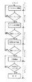
図1に示すのは、このゲーム機の動作を説明するフロー図で、その動作についてまず説明する。
【0018】
ゲーム機の動作は、ゲーム機の電源を入れるとまずCRTディスプレーにデモ画面が表示されるステップ1と、このデモ画面を見て、ゲームプレーヤがそのゲームを行うかどうかを判断し、ゲームをしようと思ったゲームプレーヤが、コインを投入し、コインスイッチをONとすると、後述する外部記憶装置としてのカセット内に記憶された複数のゲームの、それぞれに対応する代表背景画像が前記ディスプレーに表示したゲーム選択画面がデモ画面から変更表示されるステップ2と、ゲームプレーヤが前記ゲーム選択画面の代表背景画像等を見ながら操作ボタンを操作して、ゲームを選択すると、前記背景画選択画面に対応するゲームの全種類の背景画像をディスプレーに表示するステップ3と、前記全種類の背景画像の中からゲームプレーヤが所望の背景画像を選択し、選択された背景画像がディスプレーの全面に表示されるとともに、その背景画像にゲームプレーヤの顔等を写した撮影画像を合成した印刷画面をディスプレーに表示するステップ4と、この印刷画面で印刷することで良いかどうかを決定し、印刷決定スイッチを入れると、その決定された画像で印刷するステップ5とからなる。
【0019】
前記選択画面には、後述するゲームごとの代表の背景画像(前景画像や枠画像、タイトル画像も含む)をそれぞれのカセットのゲーム情報から抽出し、1つの選択画面に表示するようにしている。このように複数のカセットのゲーム情報から代表の背景画像を表示する手段については後に詳述する。
【0020】
ここで、本形態では一つのカセットに一つのゲームを記憶した例で説明するが、このようなゲーム機に限らず、一つのカセットに複数のゲームを記憶する方式のものにも適応できる。
【0021】
次に、本発明の要旨である、前述したゲーム選択画面の形成方法について説明する。
【0022】
図2において1はCPU(central processing unit)であり、このCPU1のバスには、図示しないワークRAM2と、システムROM3、カセットAのゲームROM(A)と、カセットBのゲームROM(B)、VRAM4、表示制御回路5とが接続されている。この実施の形態内において、キャラクタROM(A)、(B)を総称してキャラクタROM7と定義する。5は、CG(コンピュータグラフィック)回路等の表示制御部であり、この表示制御部5も前記バスに接続されている。
【0023】
本形態では、前記カセットA、Bのそれぞれに一つずつのゲームが記憶されている例で説明するがこれに限定されず、一つのカセットに複数のゲームを記憶しているゲーム機にも適用することができる。さらに、カセット数についても2つのカセットを使用するゲーム機について説明するが、これに限らず2つ以上のカセットを用いるものにも適用することができるのは勿論である。
【0024】
ゲーム機に電源が入ると、CPU1は、まずカセットの数を認識し、その数に応じて予めシステムROM3に用意されたカセットの数に応じたレイアウト情報を選択する。
【0025】
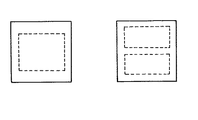
前記レイアウト情報は、図3に示すように1つのカセットしか使用されていない場合は、図3の左図、2つのカセットの場合は、同図の右図のレイアウト情報が選択される。左図のレイアウト情報が選択された場合は、使用されるカセットは一つしかないことになり、左図の点線の枠内にカセットに記憶されるゲームの代表の画面情報に対応したキャラクタコードCHCが割り当てられ、そのキャラクタコードCHCに対応した絵情報GIがキャラクタROM7から抽出されてディスプレー上に表現される。具体的には、このレイアウト情報は、システムROMのプログラムによって、VRAM4上に書き込むゲーム情報をカセットの数に応じて規制する情報である。
【0026】
この形態では、2つのカセットが存在するから、右図のレイアウト情報を選択することになる。したがって、2つのカセットのゲームの代表の画面情報に対応したキャラクタコードCHC等が上下に点線で囲まれる枠内に、それぞれ割り当てられてVRAM4に書き込まれることになる。
【0027】
このようなVRAM4への書き込みについて図4に基づき以下に詳述する。CPU1が、システムROM3のプログラムに基づき、前記カセットAのゲームROM(A)にアクセスし、キャラクタコードCHCのアドレスADに1が付されている代表画面情報に対応した代表のキャラクタコードCHCを抽出し、図3の右図の点線で囲まれる上の領域に書き込まれ、又、前記カセットBのゲームROM(B)にアクセスし、キャラクタコードCHCに1が付されている代表画面情報に対応した代表のキャラクタコードCHCを抽出し、図3の左図の点線で囲まれる下の領域に順次書き込まれる。
【0028】
この書き込みに対して前記CPU1は、カセットAから抽出した情報なのか、カセットBの情報なのかを後に認識するため、前記キャラクタコードCHCごとに第2アドレスAD2を付してVRAM4に書き込んでいる。つまり、本形態では例えばカセットAから抽出したキャラクタコードCHCをVRAM4に書き込む時には、キャラクタコードCHCのアドレスADの前に0(ゼロ)を付し、カセットBから抽出したときには、アドレスADをVRAMに書き込む前に1をまず書き込むように1ビットで制御している。従って、図4に示すように、第2アドレスAD2と、キャラクタコードCHCとが一つの固まりとして、VRAM4上に前記レイアウト情報にしたがって順次書き込まれることになる。
【0029】
前記キャラクタコードCHCは、絵コードDC、及びその絵の色コードCCとから構成されている。前記キャラクタコードCHCの絵コードDCのそれぞれがカセットAのキャラクタROM7(以下キャラクタROM(A)という)に記憶される絵情報GIに対応づけられ、前記色コードCCは図4に示すカラーパレット15に対応づけられている。前記カラーパレット15は、複数のカセットに記憶されるゲームで共通使用するようにしている。
【0030】
前記カセットAとカセットBのキャラクタコードCHCの絵コードDCはカセットA、Bごとに共通(同じ)のアドレスADが使用されているから、そのキャラクタコードCHCに基づいて絵コードDCを適用する時には、どちらのカセットに記憶されたゲームのキャラクタROM7から絵情報GIを引き出すべきなのかをまず判断しなければならない。これは、1つの絵コードDCに対応する絵情報GIが、キャラクタROM(A)にもカセットBのキャラクタROM7(以下キャラクタROM(B)という)にも存在するからである。本形態の場合、このカセットA,Bの認識には、前述した外部記憶装置としてのカセットごとに付された識別コード(第2アドレスAD2)が使用される。
【0031】
このような第2アドレスAD2を使用するものに限らず、例えば、カセットAのゲームの絵コードDCは1〜100、カセットBのゲームの絵コードDCは101〜200のアドレスADを使用するように予め定めておけば、そのアドレスADの100を基準にした「大きさ」だけを認識することにより、どちらのカセットにアクセスして絵情報GIを抽出するかを判断することが可能である。しかしながら、このように、カセットAのゲームとカセットBのゲームとで重複しないアドレスADを付し、絵情報GIを整理記憶するようにすると、新しい絵情報GIを記憶したカセットCをカセットA又はBと交換する場合に、そのカセットCが100以下のアドレスADを使って絵コードDCを記憶しているカセットなのか、100より大きいアドレスADを使ったカセットなのかによって交換するカセットA、Bが限定されてしまう不都合がある。
【0032】
勿論、前述したような不都合があるとしても、本発明の所定の目的は達成されるから、重複しないように絵コードDCを付した場合を本発明から除外するものではなく、権利範囲に含まれるものである。
【0033】
本実施形態では絵コードDCを共通のものとして使用したのは、カセットCを交換する場合、カセットA、Bのどちらでも交換できるようにするためで、前述した背景画像としての絵情報GIが気に入ったものか、あるいはそのゲーム機で人気のある絵情報GIを記憶したカセットを残して人気のないカセットと交換するといったことが自由に選択することが可能となる。また、絵情報GIをカセットのキャラクタROM7にデータ入力するグラフィックデザイナーにとっても、どのアドレスを使用するのかを気にかける必要がないので制作者側にとってもメリットがある。
【0034】
また、前述したようにして、それぞれのゲームの代表の画面情報(第2アドレスAD2+代表のキャラクタコードCHC)がVRAM4に書き込まれると、このVRAM4上に一旦書き込まれた情報に基づき、いわゆるCG回路と呼ばれるような表示制御部5により、ゲームごとに対応したキャラクタROM7から絵コードDCに応じた絵情報GIを抽出しするとともに、色コードCCに応じた色をカラーパレット15から抽出し、両者を合成する合成回路6によって前記絵情報GIに色づけを行う。そして、このように絵情報GIに色づけが行われたゲーム選択画面情報がディスプレー10上にゲーム選択画面として表示される。前記絵情報GIとは、16×16画素のビットマップデータである。
【0035】
前記表示制御部5は、前記VRAM4に書き込まれた情報から、まずキャラクタコードCHCの先頭に設けられた第2アドレスAD2を読みとり、いずれのカセットから情報を読み出すかを選択し、バス切り替え手段5Aによりバスの切り替えを行うようにしている。
【0036】
前述したゲーム選択画面は、上記形態においてカセットA,カセットBにそれぞれ一つづつのゲームしか記憶されていないゲーム機に適用したが、一つのカセットに2つ以上のゲームを記憶したものであっても適用することが可能である。この場合には、2つのゲームを記憶したカセットを例にとって説明すると、ゲームROM内に記憶されたキャラクタコードCHCの1から100のアドレスの内、1から50までと51から100までの2つの領域に、2つのゲームをそれぞれ割り当てる。そして、代表画面情報としてのキャラクタコードCHCはアドレスADの1と、アドレスADの51を抽出するように、前記システムROM3にプログラムしておけば良い。
【0037】
以上が前記ステップ2におけるゲーム選択画面の抽出方法であるが、前述したようにこのゲーム選択画面を見ながらゲームのプレーヤが、好みのゲーム(背景画像の種類)を選択スイッチによって選択する。背景画像の種類としては、その季節に合わせた春夏秋冬の風景や、卒業時期や成人式の時期などに合わせての文字や図形をレイアウトした前景やタイトル画像を含む背景画像などが考えられる。
選択スイッチによってゲームが選択されると、そのゲームが記憶されるカセットA又はBにCPU1がアクセスし、そのゲームが実行され、ゲームの背景画像が全てがディスプレー10上に縮小サイズで表示される。この画面が背景画像選択画面であり、ステップ3が終了する。
前記背景画選択画面を表示した段階、上述したゲームを選択した以降は、その選択したゲームを記憶するカセットだけにCPU1がアクセスしている状態を維持する。
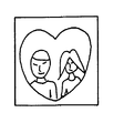
次に、ゲームプレーヤが好みの背景画を選択するため図示しないスイッチONにすると、印刷画面が表示される、ここでステップ4の終了となる。前記印刷画面は、ゲームプレーヤが選択した背景画が図5に示すようにディスプレー10に、先の背景画選択画面より大きい背景画が表示され、CCDカメラ11等で撮影された映像と合成された画面である。
【0038】
このような画像の合成は、従来から周知な、例えば、特開平7−123441号、特開平6−332122号、特開平7−95503号、特開平5−161064号などに開示されている周知の方法を適宜用いることができるが、一例として図6のようなブロック図を示す。図6は、本形態の合成部分を中心としたブロック図で、CCDカメラ11で撮影された映像は第1のフレームメモリ12で一旦記憶され、前記表示制御部5により合成回路6に送られる背景画像情報と、前記第1のフレームメモリ12の画像情報とをその合成回路6で合成し、合成された画像情報を第2のフレームメモリ13に書き、その第2のフレームメモリ13の画像情報をプリンタ14でプリント出力させるように構成してある。
【0039】
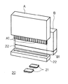
前記カセットAとBは、図7に示すように、前記ゲーム機の装置本体に設けられる、多数の電子部品21が実装された回路基板20上に、ソケット22を設け、このソケット22に着脱自在に電気的に接続できるように構成している。そして、カセットA、Bの複数の接続端子A1・・A1,B1・・B1によって、カセットA、B内のゲームROM(A)、(B)及びキャラクタROM(A)、(B)等と回路基板20上の電気回路とが電気的に接続される。
【0040】
この実施の形態では、ゲームプレーヤたるユーザの顔などをCCDカメラ11で撮影し、その自己撮影画像と、予め用意された背景画像とを合成し、その合成画像をプリンタ14で印刷(昇華化型熱印字方式)するようなゲーム機に本発明を適用した形態を示したが、これに限定されず他のゲーム機にも適応することが可能である。例えば、格闘ゲーム機の場合は、ゲームごとの代表的な格闘画面を抽出するとか、ドライビングゲームにおいては、代表的なゲームのサーキットの画面を抽出するといった具合にゲーム選択画面を作成することにより他のゲーム機にも適用することができる。
【0041】
上記実施例では、外部記憶装置であるカセット内には、キャラクタ情報CHI及び、そのカセットが選択された後のゲームプログラムを記憶したゲームROMのみを有する構成としたがこのような構成に限らず、後述するように、前記デモンストレーション画面上で前記キャラクタ情報CHIを動かすための制御プログラムをも前記ゲームROMと共に記憶し、カセットごとのシステムROMとして構成することもできる。このように構成すれば、カセットが選択される前のデモンストレーション画面をもカセット交換により変更することが可能となる。
【0042】
(形態2)
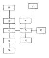
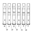
図8に示すのは、前記形態の変形例である。前記形態では、外部記憶装置としてのカセットA、B内に、絵コードDCと、その絵コードDCに対応した絵情報GIを記憶したキャラクタROM7と、前記絵コードDCと、この絵コードDCを色づけする色コードCCとのキャラクタコードCHCを記憶したゲームROMとを収納する構成としたが、これに加えてシステムROM3を基板20ではなく、カセットA、B側に設けたものである。すなわち、ゲーム機の電源が入れられスタートすると、メインソケットに挿入されたメインカセットMのシステムROM3により、デモ画面が表示され、ゲーム選択画面は、そのシステムROM3の制御プログラムによって各カセットM、A〜Eに記憶された絵情報GIが抽出されて表示される。前記キャラクタROM7とキャラクタコードCHCがキャラクタ情報CHIに相当する。
【0043】
そして、メインソケットMに接続されたシステムROM3に従ってその後のプログラムをも実行させるように構成している。
【0044】
このような構成にすることにより、メインカセットMに接続されるカセットを他のカセットと変更することによって、例えば、同じチュウリップの絵を使用する場合でも、可動する制御プログラムにより異なった順序でディスプレーに表示することで異なる演出とすることができる。
【0045】
また、前記キャラクタコードCHCをカセットごとに異なる取り決めで、このキャラクタコードCHCに対応する絵情報GIが記憶されている場合には、どのカセットから読み出されたキャラクタコードCHCであるかを判断するため、各カセットで重複しないキャラクタコードCHCのアドレスを付しておく必要がある。図8では、6本のカセットを使用する例を示しているが、例えば1〜600までのアドレスをそれぞれ100づつ割り振るようにすると良い。
【0046】
この形態2のように構成することにより、カセットを差し替えるだけで、複数カセットに渡り記憶されたキャラクタ情報CHI(キャラクタコードCHC(ゲームROM)+キャラクタROM7の情報)を基に、異なる演出でデモ画面やげゲーム選択画面を表示することができる。したがって、同じカセットを使用したゲーム機で複数の演出をすることにより、飽きのこないゲーム機を提供することができるメリットがある。
【0047】
なお、この形態2では、全てのカセットM、A〜Eに異なるプログラムを記憶させた構成を採用したが、キャラクタ情報CHIだけを記憶させたカセットとして構成し、メインソケットM以外のソケット22に挿入するようにすることもできる。このように構成すれば、キャラクタ情報CHIを変更して異なる演出としたり、ゲ−ムカセットをシステムROM3を除いたメモリ容量で作成できるから、安価にカセット作成することが可能となる。
【0052】
【発明の効果】
請求項1の発明によれば、複数のゲームの代表的な画像情報を読み出してゲーム選択画面を形成するようにしているため、複数のカセット等の外部記憶装置に記憶された複数のゲームを、カセットを意識せずにゲームごとに選択することが可能となる。より詳細には、ゲーム選択画面は、複数のゲームのそれぞれの代表的な画像情報を1つの画面で表示したものとされるため、従来のように時間差でゲームごとのデモンストレーション画面が目まぐるしく入れ替わるようなことがなくなり、プレーヤは、記憶にそれほど頼らずに好みのゲームを選択することができる。
【0054】
請求項3の発明によれば、ゲーム選択画面は、上記部分的なゲームプログラムに基づく画像を、各ゲームに割り当てられた枠内で表示させたものとすることができるため、このゲーム選択画面をデモ画面と兼用させることができる。また、このような、複数のゲームを同一の画面で表示して形成されたデモ画面によれば、プレーヤは、より一層、記憶にそれほど頼らずに好みのゲームを選択することができる。
【0055】
【0056】
【図面の簡単な説明】
【図1】本発明の実施の形態におけるゲーム機の動作説明をするためのフロー図である。
【図2】図2は図1の形態におけるシステム図である。
【図3】図3はシステムROMに記憶されたレイアウト情報を図示したものである。
【図4】図4は前記形態のブロック図である。
【図5】図5は、前記形態のCCDカメラ11の撮影映像と背景画像との合成した画像をディスプレーに表示した画面である。
【図6】図6は、前記形態のブロック図である。
【図7】図7は、カセットの基板への実装状態を示す斜視図である。
【図8】図8は、本発明の形態2の説明図である。
【符号の説明】
1・・・CPU
2・・・ワークRAM
3・・・システムROM
4・・・VRAM
6・・・表示制御部
10・・ディスプレー[0001]
BACKGROUND OF THE INVENTION
The present invention relates to a so-called multi-cassette type apparatus in which a plurality of cassettes in which information (for example, programs) used in separate games is stored in a storage device in the cassette is detachable from the game machine, and how to use the same. Regarding improvement.
[0002]
[Prior art]
As conventional multi-cassette game machines, techniques disclosed in Japanese Utility Model Laid-Open Nos. 60-135864 and 63-3886 are known.
[0003]
In the conventional technology, a socket as a plurality of cassette attachments is provided in advance in the game machine, and a selection switch for selectively connecting each cassette and the CPU of the game machine is provided. By switching, the CPU of the game machine can access the storage device of a predetermined (want to play a game) game cassette so that a desired game can be enjoyed.
[0004]
With this configuration, multiple games can be selected and played on a single game machine, which not only reduces the risk of poor connection due to the insertion and removal of the cassette and socket, but is also used in arcade game machines. In this case, users can enjoy a wide variety of games of their choice on a single game machine. From the viewpoint of the game hall manager, the same effect as that of installing the number of game machines for the added game cassette. There was an advantage that the installation space can be greatly reduced.
[0005]
[Problems to be solved by the invention]
However, when such a method of selecting a plurality of games is employed, display means such as a screen for determining which game the player selects is required. For example, in Japanese Utility Model Laid-Open No. 60-135564, demonstration information of each game stored in advance on a CRT is displayed, and a game player is made to select one game cassette by using a software selection button provided on the side of the display screen of the CRT. I am doing so. Demonstration information is, for example, the title of each game written on an acrylic board or the like as an
[0006]
However, in the multi-type game machine having the above-described conventional configuration, when the game cassette is changed or the cassette that can be stored in the game machine is changed, the information stored in the demonstration screen described above needs to be replaced or the number of cassettes is changed. In such a case, it was necessary to change the number of buttons and selection buttons installed on the side of the display screen. Therefore, it is possible to enjoy a plurality of types of games with one game machine, but in order to replace the game cassette stored in the game machine, the above-described demonstration information creation and selection buttons are used depending on the cassette to be replaced. It was difficult to say that it was practical because it required troublesome work such as changing the number.
[0007]
In addition, since the demonstration images for each game could not be displayed on the display screen at the same time, the player needs to recognize the demonstration images of all the games and select a favorite game, and is displayed with a time difference. The player has to memorize game information obtained from a plurality of demonstration screens, and the player has to perform a troublesome memory work such as selecting a cassette in which a favorite game is stored. If you forgot the features of the game that ended the demonstration, you had to review the demonstration again.
[0008]
Furthermore, since it is necessary to store the game contents in this way, there is a limit to increasing the number of cassettes that can be attached to the game machine.
[0009]
The present invention has been made to solve the above problems.
[0010]
[Means for Solving the Problems]
In order to solve the above problems, the present invention employs the following configuration.
[0011]
The invention according to the first aspect is connected to a socket connectable to a plurality of external storage devices in which one or more game presentation programs are stored, and one game presentation program is received from the plurality of external storage devices. A game machine comprising: a control unit that can be executed; and a display unit that displays information about a game, wherein the control unit recognizes the number of external storage devices connected to the socket, and Typical image information executed by the effect program stored in the external storage device is read from each external storage device, and based on the layout information that determines the layout of the game selection screen according to the number of the plurality of external storage devices. , on the display unit, and a display control means for displaying place each image information thus read out on one screen, a plurality of the representative image displayed in the display unit Executing means for executing this game presentation program corresponding to one of the image information selected by the player is read from the external storage device in game selection screen consisting of information,
It is characterized by having.
[0014]
The invention according to the second aspect is connected to a socket connectable to a plurality of external storage devices in which one or a plurality of game presentation programs are stored, and one game presentation program is transmitted from the plurality of external storage devices. A control method for controlling a game machine including a control unit that can be executed and a display unit that displays information about a game by the control unit,
Recognizing the number of external storage devices connected to the socket, the representative image information executed by the rendering program stored in the plurality of external storage devices is read from each external storage device, and the plurality of external storage devices based on the layout information defining a layout of a game selection screen according to the number of devices, the method comprising: on the display unit, and displays place each image information thus read out on a single screen,
A step of reading out a game effect program corresponding to the image information selected by the player on the game selection screen displayed on the display unit from the external storage device and executing the program ;
It is characterized by including .
[0015]
[0016]
Embodiment
1 to 6 show an image processing function for photographing a user's face or the like with the
[0017]
FIG. 1 is a flowchart for explaining the operation of the game machine. The operation will be described first.
[0018]
When the game machine is turned on, the demo screen is first displayed on the CRT display when the game machine is turned on.
[0019]
In the selection screen, representative background images (including foreground images, frame images, and title images) for each game to be described later are extracted from the game information of each cassette and displayed on one selection screen. The means for displaying the representative background image from the game information of a plurality of cassettes will be described in detail later.
[0020]
In this embodiment, an example in which one game is stored in one cassette will be described. However, the present invention is not limited to such a game machine, and can be applied to a system in which a plurality of games are stored in one cassette.
[0021]
Next, a method for forming the above-described game selection screen, which is the gist of the present invention, will be described.
[0022]
In FIG. 2,
[0023]
In this embodiment, an example in which one game is stored in each of the cassettes A and B will be described. However, the present invention is not limited to this, and the present invention is also applicable to a game machine storing a plurality of games in one cassette. can do. Furthermore, although the game machine using two cassettes will be described with respect to the number of cassettes, the present invention is not limited to this, and it is needless to say that the present invention can be applied to one using two or more cassettes.
[0024]
When the game machine is turned on, the
[0025]
As shown in FIG. 3, when only one cassette is used as shown in FIG. 3, the layout information shown in the left diagram of FIG. 3 and the right diagram of FIG. When the layout information in the left figure is selected, only one cassette is used, and the character code CHC corresponding to the representative screen information of the game stored in the cassette in the dotted line frame in the left figure Is assigned, and the picture information GI corresponding to the character code CHC is extracted from the
[0026]
In this embodiment, since there are two cassettes, the layout information shown in the right figure is selected. Therefore, character codes CHC and the like corresponding to the representative screen information of the game of the two cassettes are respectively allocated and written in the
[0027]
Such writing to the
[0028]
In response to this writing, the
[0029]
The character code CHC is composed of a picture code DC and a color code CC of the picture. Each of the picture codes DC of the character code CHC is associated with picture information GI stored in the
[0030]
Since the picture code DC of the character code CHC of the cassette A and the cassette B uses a common (same) address AD for each of the cassettes A and B, when applying the picture code DC based on the character code CHC, It must first be determined which cassette should store the picture information GI from the
[0031]
For example, the picture code DC of the game of the cassette A uses the address AD of 1 to 100, and the picture code DC of the game of the cassette B uses the address AD of 101 to 200, for example. If it is determined in advance, it is possible to determine which cassette is accessed to extract the picture information GI by recognizing only the “size” based on 100 of the address AD. However, when the address AD that does not overlap between the game of the cassette A and the game of the cassette B is added and the picture information GI is organized and stored, the cassette C storing the new picture information GI is stored in the cassette A or B. The cassettes A and B to be exchanged are limited depending on whether the cassette C is a cassette that stores picture codes DC using an address AD of 100 or less, or a cassette that uses an address AD greater than 100. There is an inconvenience.
[0032]
Of course, even if there are inconveniences as described above, the predetermined object of the present invention is achieved, so the case where the picture code DC is attached so as not to overlap is not excluded from the present invention and is included in the scope of rights. Is.
[0033]
In the present embodiment, the picture code DC is used as a common one so that when the cassette C is exchanged, both the cassettes A and B can be exchanged. It is possible to freely select whether to replace a cassette that is not popular or leave a cassette storing picture information GI that is popular with the game machine. Also, the graphic designer who inputs the picture information GI to the
[0034]
Further, as described above, when the representative screen information of each game (second address AD2 + representative character code CHC) is written in the
[0035]
The
[0036]
The game selection screen described above is applied to a game machine in which only one game is stored in each of the cassette A and cassette B in the above embodiment, but two or more games may be stored in one cassette. It is possible to apply. In this case, a cassette storing two games will be described as an example. Of the
[0037]
The above is the method for extracting the game selection screen in
When a game is selected by the selection switch, the
After the background image selection screen is displayed, after the above-described game is selected, the
Next, when the game player turns on a switch (not shown) to select a favorite background image, a print screen is displayed. Here,
[0038]
Such image synthesis is well-known, for example, as disclosed in JP-A-7-123441, JP-A-6-332122, JP-A-7-95503, JP-A-5-161064, and the like. Although the method can be used as appropriate, a block diagram as shown in FIG. 6 is shown as an example. FIG. 6 is a block diagram centering on the combining portion of the present embodiment. The image taken by the
[0039]
As shown in FIG. 7, the cassettes A and B are provided with a
[0040]
In this embodiment, the user's face as a game player is photographed by the
[0041]
In the above embodiment, the cassette which is an external storage device has only the character information CHI and the game ROM storing the game program after the cassette is selected. As will be described later, a control program for moving the character information CHI on the demonstration screen can also be stored together with the game ROM and configured as a system ROM for each cassette. If comprised in this way, it becomes possible to change the demonstration screen before a cassette is selected by cassette replacement.
[0042]
(Form 2)
FIG. 8 shows a modification of the above embodiment. In the above embodiment, the picture code DC, the
[0043]
Then, the subsequent program is also executed in accordance with the
[0044]
With this configuration, by changing the cassette connected to the main cassette M with another cassette, for example, even when using the same Chulip picture, the display can be displayed in a different order depending on the movable control program. By displaying it, it can be set as a different production.
[0045]
Further, if the character code CHC is determined differently for each cassette and the picture information GI corresponding to the character code CHC is stored, the character code CHC read from which cassette is determined. The address of the character code CHC that does not overlap in each cassette needs to be attached. Although FIG. 8 shows an example in which six cassettes are used, for example, it is preferable to allocate 100 addresses each from 1 to 600.
[0046]
With this configuration, the demonstration screen can be displayed with different effects based on the character information CHI (character code CHC (game ROM) +
[0047]
In the second embodiment, a configuration in which different programs are stored in all cassettes M and A to E is adopted. However, the
[0052]
【The invention's effect】
According to the invention of
[0054]
According to the invention of
[0055]
[0056]
[Brief description of the drawings]
FIG. 1 is a flowchart for explaining the operation of a game machine in an embodiment of the present invention.
FIG. 2 is a system diagram in the form of FIG. 1;
FIG. 3 illustrates layout information stored in a system ROM.
FIG. 4 is a block diagram of the embodiment.
FIG. 5 is a screen on which a composite image of a captured image of the
FIG. 6 is a block diagram of the embodiment.
FIG. 7 is a perspective view showing a cassette mounted on a substrate.
FIG. 8 is an explanatory diagram of
[Explanation of symbols]
1 ... CPU
2. Work RAM
3. System ROM
4 ... VRAM
6 ...
Claims (3)
上記制御部は、
前記ソケットに接続された外部記憶装置の数を認識し、上記複数の外部記憶装置に記憶された演出プログラムにより実行される代表的な画像情報を上記各外部記憶装置から読み出し、上記複数の外部記憶装置の数に応じたゲーム選択画面のレイアウトを定めるレイアウト情報に基づいて、上記表示部に、その読み出した各画像情報を1つの画面で配置し表示させる表示制御手段と、
上記表示部で表示された複数の前記代表的な画像情報からなるゲーム選択画面上においてプレーヤが選択した一の画像情報に対応するゲームの演出プログラムを前記外部記憶装置から読み出してこれを実行する実行手段と、
を有することを特徴とするゲーム機。A control unit connected to a socket connectable to a plurality of external storage devices storing one or a plurality of game presentation programs, and capable of executing a single game presentation program from the plurality of external storage devices; A display unit for displaying information on the game machine,
The control unit
Recognizing the number of external storage devices connected to the socket, the representative image information executed by the rendering program stored in the plurality of external storage devices is read from each external storage device, and the plurality of external storage devices based on the layout information defining a layout of a game selection screen according to the number of devices, on the display unit, and a display control means for displaying place each image information thus read out on a single screen,
Executing a game effect program corresponding to one piece of image information selected by the player on the game selection screen including a plurality of the representative image information displayed on the display unit and executing the program. Means,
A game machine comprising:
前記ソケットに接続された外部記憶装置の数を認識し、上記複数の外部記憶装置に記憶された演出プログラムにより実行される代表的な画像情報を上記各外部記憶装置から読み出し、上記複数の外部記憶装置の数に応じたゲーム選択画面のレイアウトを定めるレイアウト情報に基づいて、上記表示部に、その読み出した各画像情報を1つの画面で配置し表示させるステップと、
上記表示部で表示されたゲーム選択画面上においてプレーヤが選択した画像情報に対応するゲームの演出プログラムを前記外部記憶装置から読み出してこれを実行するステップと、
を含むことを特徴とするゲーム機の制御方法。A control unit connected to a socket connectable to a plurality of external storage devices storing one or a plurality of game presentation programs, and capable of executing a single game presentation program from the plurality of external storage devices; A control method for controlling a game machine having a display unit for displaying information on the control unit by a control unit,
Recognizing the number of external storage devices connected to the socket, the representative image information executed by the rendering program stored in the plurality of external storage devices is read from each external storage device, and the plurality of external storage devices based on the layout information defining a layout of a game selection screen according to the number of devices, the method comprising: on the display unit, and displays place each image information thus read out on a single screen,
A step of reading out a game effect program corresponding to the image information selected by the player on the game selection screen displayed on the display unit from the external storage device and executing the program ;
Control method for a game machine which comprises a.
Priority Applications (1)
| Application Number | Priority Date | Filing Date | Title |
|---|---|---|---|
| JP3385998A JP3845745B2 (en) | 1998-01-29 | 1998-01-29 | GAME MACHINE, AND GAME MACHINE CONTROL METHOD |
Applications Claiming Priority (1)
| Application Number | Priority Date | Filing Date | Title |
|---|---|---|---|
| JP3385998A JP3845745B2 (en) | 1998-01-29 | 1998-01-29 | GAME MACHINE, AND GAME MACHINE CONTROL METHOD |
Related Parent Applications (1)
| Application Number | Title | Priority Date | Filing Date |
|---|---|---|---|
| JP9074316A Division JPH10230079A (en) | 1997-02-18 | 1997-02-18 | Device using external storage device and method for processing information of external storage device |
Publications (3)
| Publication Number | Publication Date |
|---|---|
| JPH10230080A JPH10230080A (en) | 1998-09-02 |
| JPH10230080A5 JPH10230080A5 (en) | 2005-01-06 |
| JP3845745B2 true JP3845745B2 (en) | 2006-11-15 |
Family
ID=12398240
Family Applications (1)
| Application Number | Title | Priority Date | Filing Date |
|---|---|---|---|
| JP3385998A Expired - Fee Related JP3845745B2 (en) | 1998-01-29 | 1998-01-29 | GAME MACHINE, AND GAME MACHINE CONTROL METHOD |
Country Status (1)
| Country | Link |
|---|---|
| JP (1) | JP3845745B2 (en) |
Families Citing this family (2)
| Publication number | Priority date | Publication date | Assignee | Title |
|---|---|---|---|---|
| JP4713115B2 (en) * | 2004-09-17 | 2011-06-29 | 株式会社ジャストシステム | File display device, file display method, and file display program |
| KR20100015246A (en) | 2008-08-04 | 2010-02-12 | 삼성전자주식회사 | Storage device with display unit, method of displaying an information |
-
1998
- 1998-01-29 JP JP3385998A patent/JP3845745B2/en not_active Expired - Fee Related
Also Published As
| Publication number | Publication date |
|---|---|
| JPH10230080A (en) | 1998-09-02 |
Similar Documents
| Publication | Publication Date | Title |
|---|---|---|
| US6518939B1 (en) | Image observation apparatus | |
| CA2140955C (en) | Game signal conversion apparatus | |
| US6285381B1 (en) | Device for capturing video image data and combining with original image data | |
| JP4244919B2 (en) | Information processing apparatus and method, program, and information processing system | |
| JP2001312258A (en) | Information processing device for producing image data according to image output device, and recording medium therefor | |
| EP1130548A2 (en) | Character display method | |
| US20020149678A1 (en) | Image printing device | |
| JP3009665B1 (en) | Card making machine, card vending machine, card and card type play equipment | |
| JP3845745B2 (en) | GAME MACHINE, AND GAME MACHINE CONTROL METHOD | |
| JP3791728B2 (en) | GAME SCREEN DISPLAY CONTROL METHOD, GAME SYSTEM, AND COMPUTER-READABLE RECORDING MEDIUM | |
| JPH096326A (en) | Image display device | |
| US7092585B2 (en) | Method and apparatus for processing both static and moving images | |
| JPH10230079A (en) | Device using external storage device and method for processing information of external storage device | |
| KR100210650B1 (en) | Image Control Device with Printer | |
| CA2077945C (en) | Method for scrolling images on a screen | |
| JP5895394B2 (en) | Game shooting device, game shooting method, and game shooting program | |
| CN100489959C (en) | Real-time capturing device and method for full-screen picture | |
| JPH0728438A (en) | Amusement machine | |
| JP3035618U (en) | Image synthesis device | |
| JPH10230080A5 (en) | ||
| JP3643416B2 (en) | Image data input / output apparatus and method | |
| JP4305775B2 (en) | Video display processor for gaming machine, gaming machine, and gaming machine control method | |
| CA2216830A1 (en) | Image data printing apparatus | |
| JP4338044B2 (en) | Pachinko machine | |
| JP4639568B2 (en) | Image printing apparatus and method |
Legal Events
| Date | Code | Title | Description |
|---|---|---|---|
| A521 | Request for written amendment filed |
Free format text: JAPANESE INTERMEDIATE CODE: A523 Effective date: 20040210 |
|
| A621 | Written request for application examination |
Free format text: JAPANESE INTERMEDIATE CODE: A621 Effective date: 20040213 |
|
| A131 | Notification of reasons for refusal |
Free format text: JAPANESE INTERMEDIATE CODE: A131 Effective date: 20050104 |
|
| A521 | Request for written amendment filed |
Free format text: JAPANESE INTERMEDIATE CODE: A523 Effective date: 20050210 |
|
| A521 | Request for written amendment filed |
Free format text: JAPANESE INTERMEDIATE CODE: A523 Effective date: 20050407 |
|
| A131 | Notification of reasons for refusal |
Free format text: JAPANESE INTERMEDIATE CODE: A131 Effective date: 20050927 |
|
| A521 | Request for written amendment filed |
Free format text: JAPANESE INTERMEDIATE CODE: A523 Effective date: 20051125 |
|
| A131 | Notification of reasons for refusal |
Free format text: JAPANESE INTERMEDIATE CODE: A131 Effective date: 20060417 |
|
| A521 | Request for written amendment filed |
Free format text: JAPANESE INTERMEDIATE CODE: A523 Effective date: 20060518 |
|
| TRDD | Decision of grant or rejection written | ||
| A01 | Written decision to grant a patent or to grant a registration (utility model) |
Free format text: JAPANESE INTERMEDIATE CODE: A01 Effective date: 20060712 |
|
| A61 | First payment of annual fees (during grant procedure) |
Free format text: JAPANESE INTERMEDIATE CODE: A61 Effective date: 20060802 |
|
| R150 | Certificate of patent or registration of utility model |
Free format text: JAPANESE INTERMEDIATE CODE: R150 |
|
| FPAY | Renewal fee payment (event date is renewal date of database) |
Free format text: PAYMENT UNTIL: 20100901 Year of fee payment: 4 |
|
| LAPS | Cancellation because of no payment of annual fees |