JP3857943B2 - Disc cartridge loading device - Google Patents
Disc cartridge loading device Download PDFInfo
- Publication number
- JP3857943B2 JP3857943B2 JP2002097852A JP2002097852A JP3857943B2 JP 3857943 B2 JP3857943 B2 JP 3857943B2 JP 2002097852 A JP2002097852 A JP 2002097852A JP 2002097852 A JP2002097852 A JP 2002097852A JP 3857943 B2 JP3857943 B2 JP 3857943B2
- Authority
- JP
- Japan
- Prior art keywords
- cartridge
- magnetic head
- rack
- disk cartridge
- slide member
- Prior art date
- Legal status (The legal status is an assumption and is not a legal conclusion. Google has not performed a legal analysis and makes no representation as to the accuracy of the status listed.)
- Expired - Fee Related
Links
- 230000007246 mechanism Effects 0.000 claims description 33
- 230000007723 transport mechanism Effects 0.000 claims description 8
- 238000007599 discharging Methods 0.000 claims 1
- 230000003028 elevating effect Effects 0.000 description 16
- 238000013459 approach Methods 0.000 description 2
- 230000005540 biological transmission Effects 0.000 description 2
- 210000000078 claw Anatomy 0.000 description 2
- 230000003287 optical effect Effects 0.000 description 2
- 230000000630 rising effect Effects 0.000 description 2
- 230000000694 effects Effects 0.000 description 1
- 238000009434 installation Methods 0.000 description 1
Images






Landscapes
- Feeding And Guiding Record Carriers (AREA)
Description
【0001】
【発明の属する技術分野】
本発明は、光磁気ディスク等のディスク状記録媒体を収容したディスクカートリッジを対象として、信号の記録及び/又は再生を行なうディスク記録/再生装置において、ディスクカートリッジをカートリッジ排出位置から記録/再生位置まで移動させると共に、記録/再生位置のディスクカートリッジに対して磁気ヘッドを接近させるディスクカートリッジローディング装置に関するものである。
【0002】
【従来の技術】
従来、この種のディスクカートリッジローディング装置においては、カートリッジホルダーに挿入されたディスクカートリッジを、先ずカートリッジホルダー内で略水平方向に搬送した後、カートリッジホルダーを略垂直方向に下降させて、ディスクカートリッジを信号記録/再生位置に設置することが行なわれている。
該ディスクカートリッジローディング装置においては、カートリッジホルダー内のディスクカートリッジを往復移動させる第1スライド部材と、カートリッジホルダー又はベースシャーシを昇降させると共に磁気ヘッドを昇降させる第2のスライド部材とを設けて、モータの駆動力を先ず第1スライド部材に伝えて、カートリッジホルダー内のディスクカートリッジをカートリッジ排出位置からカートリッジ引き込み位置まで移動させた後、モータの駆動力を第2スライド部材に伝えて、カートリッジホルダー内のディスクカートリッジをカートリッジ引き込み位置から信号記録/再生位置まで移動させると共に、信号記録/再生位置のディスクカートリッジに対して磁気ヘッドを接近させる。
【0003】
【発明が解決しようとする課題】
しかしながら、従来のディスクカートリッジローディング装置においては、第1スライド部材の駆動から第2スライド部材の駆動へ動力伝達経路を切り替える必要があるため、機構が複雑となる問題があった。
そこで本発明の目的は、従来よりも簡易な機構でディスクカートリッジをカートリッジ排出位置から記録/再生位置まで移動させることが出来るディスクカートリッジローディング装置を提供することである。
【0004】
【課題を解決する為の手段】
本発明に係るディスクカートリッジローディング装置は、モータ(71)によって回転駆動されるピニオン(72)と、該ピニオン(72)と噛合するラック(24)が形成されたスライド部材(2)とを具え、該ラック(24)は、直線上を伸びる直線部(25)と円弧線上を伸びる円弧部(26)とを有している。
ピニオン(72)がラック(24)の直線部(25)と噛合してスライド部材(2)を往復移動させることにより、ディスクカートリッジ(10)をカートリッジ排出位置とカートリッジ引き込み位置の間で往復移動させる。
又、ピニオン(72)がラック(24)の円弧部(26)と噛合してスライド部材(2)を回動させることにより、ディスクカートリッジ(10)をカートリッジ引き込み位置と記録/再生位置の間で往復移動させると共に、記録/再生位置のディスクカートリッジ(10)に対して磁気ヘッド(61)を接近離間させる。
【0005】
上記本発明のディスクカートリッジローディング装置においては、ディスクカートリッジ(10)がカートリッジ排出位置に設置されている状態では、ピニオン(72)はラック(24)の直線部(25)の円弧部(26)とは反対側の端部と噛合しており、この状態からモータ(71)が回転を開始すると、ピニオン(72)がラック(24)を駆動することによって、スライド部材(2)は一方向に移動する。該スライド部材(2)の移動によって、ディスクカートリッジ(10)がカートリッジ排出位置からカートリッジ引き込み位置まで搬送される。
次にピニオン(72)はラック(24)の円弧部(26)と噛合し、ラック(24)が円弧部(26)を駆動することによって、スライド部材(2)は一方向に回動する。該スライド部材(2)の回動に伴って、ディスクカートリッジ(10)がカートリッジ引き込み位置から記録/再生位置まで移動すると共に、記録/再生位置のディスクカートリッジ(10)に対して磁気ヘッド(61)が接近する。
【0006】
本発明に係るディスクカートリッジローディング装置は、より具体的な構成において、
ディスクカートリッジ(10)を収容すべきカートリッジホルダー(3)を具え、該カートリッジホルダー(3)の往復移動によってディスクカートリッジ(10)をカートリッジ引き込み位置と記録/再生位置の間で往復移動させるカートリッジホルダー機構と、
カートリッジホルダー(3)内のディスクカートリッジ(10)をカートリッジ排出位置とカートリッジ引き込み位置の間で往復移動させるカートリッジ搬送機構と、
記録/再生位置のディスクカートリッジ(10)に対して磁気ヘッド(61)を接近離間させる磁気ヘッド機構と、
モータ(71)によって回転駆動されるピニオン(72)と、該ピニオン(72)と噛合するラック(24)が形成されたスライド部材(2)とを具え、該ラック(24)は、直線上を伸びる直線部(25)と円弧線上を伸びる円弧部(26)とを有する原動機構
とから構成される。
前記原動機構のピニオン(72)がラック(24)の直線部(25)と噛合してスライド部材(2)を移動させることにより、該スライド部材(2)によってカートリッジ搬送機構が駆動され、ピニオン(72)がラック(24)の円弧部(26)と噛合してスライド部材(2)を回動させることによって、該回動に連動してカートリッジホルダー機構と磁気ヘッド機構が動作する。
【0007】
カートリッジ搬送機構は、原動機構のスライド部材(2)に係合すると共にカートリッジホルダー(3)内のディスクカートリッジ(10)に係合可能なカートリッジ引き込みレバー(8)を具え、スライド部材(2)の駆動力がカートリッジ引き込みレバー(8)を介してディスクカートリッジ(10)に伝えられる。
これによって、ディスクカートリッジ(10)はカートリッジ排出位置からカートリッジ引き込み位置まで移動する。
【0008】
カートリッジホルダー機構は、カートリッジホルダー(3)を記録/再生位置に向かって押圧するバネ手段を具え、原動機構のピニオン(72)がラック(24)の直線部(25)と噛合した状態で、スライド部材(2)は前記バネ手段に抗してカートリッジホルダー(3)を持ち上げ、ピニオン(72)がラック(24)の円弧部(26)と噛合した状態で、スライド部材(2)は前記バネ手段によるカートリッジホルダー(3)の押圧を許容する。
これによって、カートリッジホルダー(3)内のディスクカートリッジ(10)は、前記バネ手段の付勢力によってカートリッジ引き込み位置から記録/再生位置まで移動し、記録/再生位置に押圧保持される。
【0009】
磁気ヘッド機構は、磁気ヘッド(61)を記録/再生位置のディスクカートリッジ(10)に向かって押圧するバネ手段を具え、原動機構のピニオン(72)がラック(24)の直線部(25)と噛合した状態で、スライド部材(2)は前記バネ手段に抗して磁気ヘッド(61)を持ち上げ、ピニオン(72)がラック(24)の円弧部(26)と噛合した状態で、スライド部材(2)は前記バネ手段による磁気ヘッド(61)の押圧を許容する。これによって、磁気ヘッド(61)は、ディスクカートリッジ(10)から離間した位置からディスクカートリッジ(10)に向かって付勢され、ディスクカートリッジ(10)のディスク面に圧接される。
【0010】
【発明の効果】
本発明に係るディスクカートリッジローディング装置によれば、単一のスライド部材によって、ディスクカートリッジ(10)をカートリッジ排出位置からカートリッジ引き込み位置まで移動させた後、該ディスクカートリッジ(10)をカートリッジ引き込み位置から記録/再生位置まで移動させると共に、記録/再生位置のディスクカートリッジ(10)に対して磁気ヘッド(61)を接近させることが出来るので、従来の如く2つのスライド部材によって上記動作を実現する場合に比べて、機構が簡易となる。
【0011】
【発明の実施の形態】
以下、本発明の実施の形態につき、図面に沿って具体的に説明する。
全体構成
本発明に係るディスクカートリッジローディング装置は、図1に示す如く本体シャーシ(1)上に、ディスクカートリッジ(図示省略)を収容すべきカートリッジホルダー(3)を具え、該カートリッジホルダー(3)の上面には、ホルダー昇降レバー(4)が設置されている。
又、図1に示す如く、本体シャーシ(1)の底板部(12)上には、ピックアップ装置(5)が往復移動可能に配備されている。ピックアップ装置(5)は、図2に示す如くベース(52)上に光学ピックアップ(51)を搭載して構成されている。
【0012】
又、図1に示す如く、本体シャーシ(1)上には磁気ヘッド装置(6)が回動可能に配備されており、先端部に設けた磁気ヘッド(61)をカートリッジホルダー(3)内のディスクカートリッジ(図示省略)のディスク面に圧接せしめることが可能となっている。
更に又、本体シャーシ(1)の左側の側板部(11)には、スライド部材(2)が設置されており、該スライド部材(2)をモータ(図示省略)の駆動によって往復移動させることによって、ディスクカートリッジのローディングが可能となっている。
【0013】
尚、ピックアップ装置(5)と磁気ヘッド装置(6)は一体となってディスク半径方向に往復移動し、ディスクカートリッジのディスクに対する信号の記録及び再生を行なう。
【0014】
カートリッジホルダー機構
図1に示す如く、本体シャーシ(1)は底板部(12)の両側部に一対の側板部(11)(11)を突設して構成され、該本体シャーシ(1)の両側板部(11)(11)間に、カートリッジホルダー(3)が昇降可能に支持されている。カートリッジホルダー(3)は、その上面に図4に示す如くバネ(30)が設置され、該バネ(30)の付勢力によって下方へ押圧されている。
【0015】
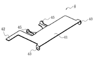
図6に示す如く、ホルダー昇降レバー(4)は、レバー本体(41)の前方両側部に支軸(43)(43)が突設されており、該支軸(43)(43)は図1に示す如く本体シャーシ(1)の両側板部(11)(11)に枢支されている。又、ホルダー昇降レバー(4)には、図6の如くレバー本体(41)の後方に、一対の支軸(45)(45)が突設され、該支軸(45)(45)は、図9に示す如くカートリッジホルダー(3)の上面に設けた一対の軸受け部(31)(31)によって枢支されている。更にホルダー昇降レバー(4)には、図6に示す如くL字状の突出部(42)が形成されている。該突出部(42)の先端は、図1の如くスライド部材(2)の上端面(21)と対向している。
【0016】
上記カートリッジホルダー機構においては、ホルダー昇降レバー(4)が支軸(43)(43)を中心として回動すると、該回動に伴ってカートリッジホルダー(3)が昇降し、該カートリッジホルダー(3)内のディスクカートリッジがカートリッジ引き込み位置と記録/再生位置の間で往復移動することになる。
【0017】
カートリッジ搬送機構
カートリッジホルダー(3)の側面には、図8(a)(b)(c)に示すカートリッジ引き込みレバー(8)が取り付けられている。該カートリッジ引き込みレバー(8)は、ベース(80)の後方端部に回動中心となる枢軸(85)を具え、ベース(80)に突設した弾性片(83)の先端部をカートリッジホルダー(3)の端部に摺接させることによって、ベース(80)に時計方向の回転付勢力を与えている。
又、カートリッジ引き込みレバー(8)には、ディスクカートリッジの前方端面によって押圧されるべき突片(84)と、ディスクカートリッジの側面に形成された凹部に係合すべき爪片(82)と、前記スライド部材(2)と係合すべきアーム(81)とが突設されている。
更に又、カートリッジ引き込みレバー(8)には、図示省略するカム溝と係合してベース(80)の姿勢を制御するためのカムフォロワー(86)が突設されている。
【0018】
上記カートリッジ搬送機構においては、カートリッジホルダー(3)内にディスクカートリッジを挿入すると、該ディスクカートリッジの前方端面がカートリッジ引き込みレバー(8)の突片(84)に当接すると共に、該ディスクカートリッジの側面の凹部に爪片(82)が係合することになる。この状態で、カートリッジ引き込みレバー(8)が前後に移動すると、これに伴ってカートリッジホルダー(3)内のディスクカートリッジは、カートリッジ排出位置とカートリッジ引き込み位置の間で往復移動することになる。
【0019】
磁気ヘッド機構
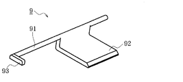
図1に示す如く、本体シャーシ(1)の後部には、両側板部(11)(11)に磁気ヘッド昇降レバー(9)が架設されている。該磁気ヘッド昇降レバー(9)は、図5に示す如くL字状のレバー部(92)と、該レバー部(92)の基端部に突設されたシャフト部(91)と、該シャフト部(91)の一端に突設されたアーム部(93)とを具えている。該磁気ヘッド昇降レバー(9)は、図示省略する第1スプリングによって時計方向に回転付勢されている。
【0020】
図1の如く磁気ヘッド装置(6)は、基端部にアーム(62)を突設すると共に、先端部に磁気ヘッド(61)を突設しており、図示省略する第2スプリングによって時計方向に回転付勢されている。
磁気ヘッド昇降レバー(9)のレバー部(92)の先端は、磁気ヘッド装置(6)のアーム(62)の先端と対向しており、磁気ヘッド昇降レバー(9)を前記第1スプリングの付勢によって時計方向に回転させることにより、磁気ヘッド装置(6)を前記第2スプリングの付勢に抗して反時計方向に回転させることが可能である。
【0021】
上記磁気ヘッド機構においては、磁気ヘッド昇降レバー(9)が前記第1スプリングの付勢によって時計方向に回転すると、磁気ヘッド装置(6)は前記第2スプリングの付勢に抗して反時計方向に回転し、これに伴って磁気ヘッド(61)がディスクカートリッジから離間する。又、磁気ヘッド昇降レバー(9)が前記第1スプリングの付勢に抗して反時計方向に回転すると、磁気ヘッド装置(6)は前記第2スプリングの付勢によって時計方向に回転し、これに伴って磁気ヘッド(61)がディスクカートリッジに接近し、ディスク面に圧接されることになる。
【0022】
原動機構
スライド部材(2)は、図7(a)(b)に示す如く前後方向に長い帯板状に形成され、その長手方向に沿ってラック(24)が形成されている。該ラック(24)は、水平直線に沿って伸びる直線部(25)と、該直線部(25)の前方端から円弧線に沿って斜め上方へ伸びる円弧部(26)とから構成されている。
又、スライド部材(2)の本体シャーシ(1)側の側面には、前後の異なる高さ位置に第1ピン(22)及び第2ピン(23)が突設されると共に、前方側の上端部に、互いに対向する一対の突片(27)(27)が形成されている。
スライド部材(2)の一対の突片(27)(27)の間には、図1の如くカートリッジ引き込みレバー(8)のアーム(81)の先端部が侵入している。これによって、スライド部材(2)とカートリッジ引き込みレバー(8)とは一体となって前後方向に移動することになる。
【0023】
一方、本体シャーシ(1)の左側の側板部(11)には、図3に示す如く、前後に段差を有して第1ガイド溝(13)と第2ガイド溝(16)が開設されている。第1ガイド溝(13)は、水平直線に沿って伸びる直線部(14)と、該直線部(14)の後方端から斜め下方へ伸びる円弧部(15)とから構成されている。又、第2ガイド溝(16)は、水平直線に沿って伸びる直線部(17)と、該直線部(17)の後方端から斜め下方へ伸びる円弧部(19)と、直線部(17)と円弧部(19)を滑らかに繋ぐ連結部(18)とから構成されている。ここで、第2ガイド溝(16)の円弧部(19)は、第1ガイド溝(13)の円弧部(15)の終端を中心とする円弧線に沿って伸びている。
前記スライド部材(2)の第1ピン(22)及び第2ピン(23)はそれぞれ本体シャーシ(1)の第1ガイド溝(13)及び第2ガイド溝(16)に係合しており、これによってスライド部材(2)の往復移動(水平移動及び回動)が案内されている。
【0024】
本体シャーシ(1)の左側の側板部(11)には、図9に示す如くモータ(71)が取り付けられており、該モータ(71)は、歯車機構(7)を介して、図1の如く側板部(11)に取り付けられたピニオン(72)に連繋している。該ピニオン(72)は、ホルダー昇降レバー(4)のラック(24)に噛合している。
従って、ピニオン(72)がスライド部材(2)のラック(24)の直線部(25)と後方端にて噛合している状態からモータ(71)が起動し、ピニオン(72)が時計方向に回転すると、スライド部材(2)は後方へ駆動されることになる。その後、ピニオン(72)はスライド部材(2)のラック(24)の円弧部(26)と噛合することになり、この状態でピニオン(72)が更に時計方向に回転すると、スライド部材(2)は時計方向に回転駆動されることになる。
【0025】
カートリッジローディング動作
図10(a)に示すカートリッジエジェクト状態では、スライド部材(2)の第1ピン(22)は本体シャーシ(1)の第1ガイド溝(13)の直線部(14)に係合し、第2ピン(23)は第2ガイド溝(16)に係合している。ホルダー昇降レバー(4)の突出部(42)はスライド部材(2)の上端面(21)に摺接しており、カートリッジホルダー(3)は上昇端に保持されている。
又、磁気ヘッド昇降レバー(9)は、前記第1スプリングの付勢によって時計方向に回動しており、該磁気ヘッド昇降レバー(9)のレバー部先端(92a)は磁気ヘッド装置(6)のアーム(62)を下圧している。これに伴って磁気ヘッド装置(6)は前記第2スプリングの付勢に抗して反時計方向に回動し、磁気ヘッド(61)は上昇端に保持されている。
【0026】
この状態でカートリッジホルダー(3)内にディスクカートリッジ(10)を挿入すると、図示省略するスイッチがオンとなって、モータ(71)が起動し、ピニオン(72)が時計方向の回転を開始して、スライド部材(2)のラック(24)の直線部(25)を駆動する。これによって、スライド部材(2)は図10(b)の如く後方端まで移動する。
スライド部材(2)の移動によって前記カートリッジ引き込みレバー(8)が駆動されると、カートリッジ引き込みレバー(8)の移動に伴って、カートリッジホルダー(3)内のディスクカートリッジ(10)がカートリッジ排出位置からカートリッジ引き込み位置まで水平に搬送されることになる。
【0027】
図10(b)に示すカートリッジ引き込み状態では、ピニオン(72)はスライド部材(2)のラック(24)の直線部(25)と円弧部(26)の境界位置(24a)に噛合している。又、スライド部材(2)の第1ピン(22)は本体シャーシ(1)の第1ガイド溝(13)の直線部(14)の終端に位置し、第2ピン(23)は第2ガイド溝(16)の直線部(17)の終端に位置している。
又、スライド部材(2)の後方端部(2a)が磁気ヘッド昇降レバー(9)のアーム部(93)に摺接している。
【0028】
この状態から更にピニオン(72)が時計方向に回転すると、図11(a)に示す如くピニオン(72)はスライド部材(2)のラック(24)の円弧部(26)に噛合する。又、スライド部材(2)の第1ピン(22)は本体シャーシ(1)の第1ガイド溝(13)の円弧部(15)に係合すると共に、第2ピン(23)は第2ガイド溝(16)の円弧部(19)に係合して、スライド部材(2)は、第1ピン(22)を中心として時計方向に回動することになる。
尚、スライド部材(2)が回動しても、スライド部材(2)の突片(27)(27)とカートリッジ引き込みレバー(8)のアーム(81)との係合は外れない。
【0029】
スライド部材(2)の上端面(21)に突出部(42)が摺接しているホルダー昇降レバー(4)は、スライド部材(2)の時計方向の回動による上端面(21)の下降に伴って、反時計方向の回転を開始する。該ホルダー昇降レバー(4)の反時計方向の回転に伴って、カートリッジホルダー(3)が前記バネ(30)の付勢によって降下する。その後、スライド部材(2)の上端面(21)は、ホルダー昇降レバー(4)の突出部(42)から離間する。これによって、カートリッジホルダー(3)内のディスクカートリッジ(10)は、前記バネ(30)の付勢力を受けて、本体シャーシ(1)上の記録/再生位置に押圧保持されることになる。
この結果、光学ピックアップ(51)によって、ディスクカートリッジ(10)のディスクから信号を再生することが可能となる。
【0030】
又、スライド部材(2)の後方端部(2a)が磁気ヘッド昇降レバー(9)のアーム部(93)を押し上げ、磁気ヘッド昇降レバー(9)を反時計方向に回転させる。該磁気ヘッド昇降レバー(9)のレバー部(92)の上昇に伴って、磁気ヘッド装置(6)が時計方向に回転し、磁気ヘッド(61)がカートリッジホルダー(3)内のディスクカートリッジ(10)に向かって降下する。
【0031】
最終的に図11(b)の如く、ピニオン(72)がスライド部材(2)のラック(24)の円弧部(26)の終端部に噛合し、スライド部材(2)の第2ピン(23)が本体シャーシ(1)の第2ガイド溝(16)の円弧部(19)の終端に達する過程で、磁気ヘッド装置(6)は更に時計方向に回動して、磁気ヘッド(61)が、記録/再生位置のディスクカートリッジ(10)のディスク面に圧接されることになる。
この結果、磁気ヘッド(61)によって、ディスクカートリッジ(10)のディスクに信号を記録することが可能となる。
【0032】
その後、ディスクカートリッジ(10)を排出する場合には、モータ(71)が逆転して、ピニオン(72)が反時計方向に回転する。これによって、図11(b)の状態から図11(a)、図10(b)の状態を経て、最終的に図10(a)に示すカートリッジ排出状態に戻り、ディスクカートリッジ(10)の取り出しが可能となる。
【0033】
上述の如く本発明に係るディスクカートリッジローディング装置によれば、スライド部材(2)に形成したラック(24)の直線部(25)をピニオン(72)によって駆動することにより、ディスクカートリッジ(10)をカートリッジ排出位置からカートリッジ引き込み位置まで移動させることが出来、引き続いてラック(24)の円弧部(26)をピニオン(72)によって駆動することにより、ディスクカートリッジ(10)をカートリッジ引き込み位置から記録/再生位置まで移動させると共に、記録/再生位置のディスクカートリッジ(10)に対して磁気ヘッド(61)を接近させることが出来る。
従って、従来の如く2つのスライド部材によって上記動作を実現する場合に比べて、部品点数が削減され、動力伝達経路の切替えも不要となって機構が簡易となる。
【図面の簡単な説明】
【図1】本発明に係るディスクカートリッジローディング装置の斜視図である。
【図2】ピックアップ装置の斜視図である。
【図3】本体シャーシの斜視図である。
【図4】カートリッジホルダーの斜視図である。
【図5】磁気ヘッド昇降レバーの斜視図である。
【図6】ホルダー昇降レバーの斜視図である。
【図7】スライド部材の斜視図である。
【図8】カートリッジ引き込みレバーの斜視図である。
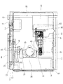
【図9】本発明に係るディスクカートリッジローディング装置を示す透視平面図である。
【図10】該ディスクカートリッジローディング装置におけるローディング動作の前半を表わす透視側面図である。
【図11】該ディスクカートリッジローディング装置におけるローディング動作の後半を表わす透視側面図である。
【符号の説明】
(1) 本体シャーシ
(2) スライド部材
(24) ラック
(25) 直線部
(26) 円弧部
(3) カートリッジホルダー
(4) ホルダー昇降レバー
(5) ピックアップ装置
(6) 磁気ヘッド装置
(7) 歯車機構
(72) ピニオン[0001]
BACKGROUND OF THE INVENTION
The present invention relates to a disk recording / reproducing apparatus for recording and / or reproducing signals for a disk cartridge containing a disk-shaped recording medium such as a magneto-optical disk, and the disk cartridge is moved from the cartridge ejection position to the recording / reproduction position. The present invention relates to a disk cartridge loading apparatus that moves and moves a magnetic head closer to a disk cartridge at a recording / reproducing position.
[0002]
[Prior art]
Conventionally, in this type of disk cartridge loading apparatus, a disk cartridge inserted in a cartridge holder is first transported in a substantially horizontal direction in the cartridge holder, and then the cartridge holder is lowered in a substantially vertical direction to signal the disk cartridge. Installation at a recording / reproducing position is performed.
In the disk cartridge loading apparatus, a first slide member that reciprocates the disk cartridge in the cartridge holder and a second slide member that moves the cartridge holder or the base chassis up and down and moves the magnetic head up and down are provided. First, the driving force is transmitted to the first slide member, and the disk cartridge in the cartridge holder is moved from the cartridge ejection position to the cartridge retracting position. Then, the driving force of the motor is transmitted to the second slide member, and the disk in the cartridge holder is transferred. The cartridge is moved from the cartridge drawing position to the signal recording / reproducing position, and the magnetic head is brought close to the disk cartridge at the signal recording / reproducing position.
[0003]
[Problems to be solved by the invention]
However, the conventional disk cartridge loading apparatus has a problem in that the mechanism is complicated because it is necessary to switch the power transmission path from driving the first slide member to driving the second slide member.
SUMMARY OF THE INVENTION Accordingly, an object of the present invention is to provide a disk cartridge loading device capable of moving a disk cartridge from a cartridge discharge position to a recording / reproducing position with a simpler mechanism than before.
[0004]
[Means for solving the problems]
The disk cartridge loading device according to the present invention comprises a pinion (72) rotated by a motor (71), and a slide member (2) formed with a rack (24) meshing with the pinion (72). The rack (24) has a straight portion (25) extending on a straight line and an arc portion (26) extending on an arc line.
The pinion (72) meshes with the linear part (25) of the rack (24) and reciprocates the slide member (2), thereby reciprocating the disk cartridge (10) between the cartridge ejection position and the cartridge retracting position. .
Further, the pinion (72) meshes with the arc portion (26) of the rack (24) and rotates the slide member (2), so that the disk cartridge (10) is moved between the cartridge retracted position and the recording / reproducing position. While reciprocating, the magnetic head (61) is moved closer to and away from the disk cartridge (10) at the recording / reproducing position.
[0005]
In the disk cartridge loading device of the present invention, in the state where the disk cartridge (10) is installed at the cartridge discharge position, the pinion (72) is connected to the arc part (26) of the linear part (25) of the rack (24). Is engaged with the opposite end, and when the motor (71) starts rotating from this state, the pinion (72) drives the rack (24), so that the slide member (2) moves in one direction. To do. By the movement of the slide member (2), the disk cartridge (10) is conveyed from the cartridge discharge position to the cartridge drawing position.
Next, the pinion (72) meshes with the arc part (26) of the rack (24), and the rack (24) drives the arc part (26), whereby the slide member (2) rotates in one direction. As the slide member (2) rotates, the disk cartridge (10) moves from the cartridge retracted position to the recording / reproducing position, and the magnetic head (61) with respect to the disk cartridge (10) at the recording / reproducing position. Approaches.
[0006]
The disk cartridge loading device according to the present invention has a more specific configuration,
A cartridge holder mechanism having a cartridge holder (3) to receive a disk cartridge (10) and reciprocating the disk cartridge (10) between a cartridge retracting position and a recording / reproducing position by reciprocating the cartridge holder (3) When,
A cartridge transport mechanism for reciprocally moving the disk cartridge (10) in the cartridge holder (3) between the cartridge discharge position and the cartridge pull-in position;
A magnetic head mechanism for moving the magnetic head (61) closer to and away from the disk cartridge (10) at the recording / reproducing position;
A pinion (72) rotated by a motor (71) and a slide member (2) formed with a rack (24) meshing with the pinion (72) are provided. The rack (24) is arranged on a straight line. It is comprised from the drive mechanism which has the linear part (25) extended, and the circular arc part (26) extended on a circular arc line.
When the pinion (72) of the driving mechanism meshes with the linear portion (25) of the rack (24) and moves the slide member (2), the cartridge transport mechanism is driven by the slide member (2), and the pinion ( 72) meshes with the circular arc portion (26) of the rack (24) to rotate the slide member (2), whereby the cartridge holder mechanism and the magnetic head mechanism operate in conjunction with the rotation.
[0007]
The cartridge transport mechanism includes a cartridge pull-in lever (8) that engages with the slide member (2) of the driving mechanism and engages with the disk cartridge (10) in the cartridge holder (3). The driving force is transmitted to the disk cartridge (10) through the cartridge pulling lever (8).
As a result, the disk cartridge (10) moves from the cartridge ejection position to the cartridge drawing position.
[0008]
The cartridge holder mechanism includes a spring means for pressing the cartridge holder (3) toward the recording / reproducing position, and slides in a state where the pinion (72) of the driving mechanism is engaged with the linear portion (25) of the rack (24). The member (2) lifts the cartridge holder (3) against the spring means, and the slide member (2) is in the state where the pinion (72) is engaged with the arc portion (26) of the rack (24). Allows the cartridge holder (3) to be pressed.
As a result, the disk cartridge (10) in the cartridge holder (3) is moved from the cartridge retracted position to the recording / reproducing position by the urging force of the spring means, and is pressed and held at the recording / reproducing position.
[0009]
The magnetic head mechanism includes spring means for pressing the magnetic head (61) toward the disk cartridge (10) at the recording / reproducing position, and the pinion (72) of the driving mechanism is connected to the linear portion (25) of the rack (24). In the engaged state, the slide member (2) lifts the magnetic head (61) against the spring means, and the pinion (72) is engaged with the arc portion (26) of the rack (24), 2) allows the magnetic head (61) to be pressed by the spring means. Thus, the magnetic head (61) is urged toward the disk cartridge (10) from a position separated from the disk cartridge (10), and is pressed against the disk surface of the disk cartridge (10).
[0010]
【The invention's effect】
According to the disk cartridge loading device of the present invention, after the disk cartridge (10) is moved from the cartridge discharge position to the cartridge retracted position by the single slide member, the disk cartridge (10) is recorded from the cartridge retracted position. The magnetic head (61) can be moved close to the recording / reproducing position and the disk cartridge (10) at the recording / reproducing position, so that the above operation is realized by two slide members as in the prior art. This simplifies the mechanism.
[0011]
DETAILED DESCRIPTION OF THE INVENTION
Hereinafter, embodiments of the present invention will be specifically described with reference to the drawings.
Overall configuration A disk cartridge loading apparatus according to the present invention comprises a cartridge holder (3) for housing a disk cartridge (not shown) on a main chassis (1) as shown in FIG. On the upper surface of (3), a holder lifting lever (4) is installed.
Further, as shown in FIG. 1, a pickup device (5) is disposed on the bottom plate portion (12) of the main chassis (1) so as to be reciprocally movable. The pickup device (5) is configured by mounting an optical pickup (51) on a base (52) as shown in FIG.
[0012]
Further, as shown in FIG. 1, a magnetic head device (6) is rotatably disposed on the main body chassis (1), and the magnetic head (61) provided at the tip portion is placed in the cartridge holder (3). It is possible to press the disk surface of a disk cartridge (not shown).
Furthermore, a slide member (2) is installed on the left side plate (11) of the main chassis (1), and the slide member (2) is reciprocated by driving a motor (not shown). The disk cartridge can be loaded.
[0013]
Incidentally, the pickup device (5) and the magnetic head device (6) integrally move back and forth in the radial direction of the disk, and record and reproduce signals on the disk of the disk cartridge.
[0014]
Cartridge holder mechanism As shown in FIG. 1, the main body chassis (1) is constructed by projecting a pair of side plate portions (11) and (11) on both sides of the bottom plate portion (12). A cartridge holder (3) is supported between the side plate portions (11) and (11) of 1) so as to be movable up and down. The cartridge holder (3) is provided with a spring (30) on its upper surface as shown in FIG. 4, and is pressed downward by the urging force of the spring (30).
[0015]
As shown in FIG. 6, the holder elevating lever (4) has support shafts (43) and (43) projecting from both front sides of the lever body (41), and the support shafts (43) and (43) are shown in FIG. As shown in FIG. 1, it is pivotally supported on both side plate portions (11) and (11) of the main chassis (1). In addition, as shown in FIG. 6, a pair of support shafts (45) and (45) project from the holder elevating lever (4) behind the lever body (41), and the support shafts (45) and (45) As shown in FIG. 9, it is pivotally supported by a pair of bearing portions (31) (31) provided on the upper surface of the cartridge holder (3). Further, the holder elevating lever (4) is formed with an L-shaped protrusion (42) as shown in FIG. The tip of the projecting portion (42) faces the upper end surface (21) of the slide member (2) as shown in FIG.
[0016]
In the cartridge holder mechanism, when the holder elevating lever (4) rotates about the support shaft (43) (43), the cartridge holder (3) moves up and down along with the rotation, and the cartridge holder (3) The disc cartridge inside moves back and forth between the cartridge retracted position and the recording / reproducing position.
[0017]
Cartridge transport mechanism A cartridge pull-in lever (8) shown in FIGS. 8 (a), (b) and (c) is attached to the side surface of the cartridge holder (3). The cartridge pull-in lever (8) has a pivot (85) as a rotation center at the rear end of the base (80), and the tip of the elastic piece (83) protruding from the base (80) is connected to the cartridge holder ( By making sliding contact with the end of 3), a clockwise rotational biasing force is applied to the base (80).
The cartridge pull-in lever (8) includes a protrusion (84) to be pressed by the front end surface of the disk cartridge, a claw piece (82) to be engaged with a recess formed on the side surface of the disk cartridge, An arm (81) to be engaged with the slide member (2) is projected.
Furthermore, a cam follower (86) is provided on the cartridge pull-in lever (8) so as to be engaged with a cam groove (not shown) to control the posture of the base (80).
[0018]
In the cartridge transport mechanism, when a disc cartridge is inserted into the cartridge holder (3), the front end surface of the disc cartridge comes into contact with the protruding piece (84) of the cartridge pull-in lever (8) and the side surface of the disc cartridge is The claw piece (82) is engaged with the recess. In this state, when the cartridge pull-in lever (8) is moved back and forth, the disk cartridge in the cartridge holder (3) is reciprocated between the cartridge discharge position and the cartridge pull-in position.
[0019]
Magnetic head mechanism As shown in FIG. 1, a magnetic head elevating lever (9) is installed on both side plates (11) and (11) at the rear of the main body chassis (1). As shown in FIG. 5, the magnetic head elevating lever (9) includes an L-shaped lever portion (92), a shaft portion (91) protruding from the base end portion of the lever portion (92), and the shaft. An arm portion (93) projecting from one end of the portion (91). The magnetic head elevating lever (9) is urged to rotate clockwise by a first spring (not shown).
[0020]
As shown in FIG. 1, the magnetic head device (6) has an arm (62) projecting at the base end portion and a magnetic head (61) projecting at the distal end portion. Is urged to rotate.
The tip of the lever portion (92) of the magnetic head lifting lever (9) is opposed to the tip of the arm (62) of the magnetic head device (6), and the magnetic head lifting lever (9) is attached to the first spring. By rotating clockwise by the force, the magnetic head device (6) can be rotated counterclockwise against the bias of the second spring.
[0021]
In the magnetic head mechanism, when the magnetic head elevating lever (9) is rotated clockwise by the bias of the first spring, the magnetic head device (6) is counterclockwise against the bias of the second spring. Accordingly, the magnetic head (61) is separated from the disk cartridge. When the magnetic head elevating lever (9) rotates counterclockwise against the bias of the first spring, the magnetic head device (6) rotates clockwise by the bias of the second spring. As a result, the magnetic head (61) approaches the disk cartridge and comes into pressure contact with the disk surface.
[0022]
Driving mechanism The slide member (2) is formed in a long strip shape in the front-rear direction as shown in FIGS. 7 (a) and 7 (b), and a rack (24) is formed along the longitudinal direction thereof. . The rack (24) includes a straight line portion (25) extending along a horizontal straight line, and an arc portion (26) extending obliquely upward along a circular arc line from the front end of the straight line portion (25). .
In addition, a first pin (22) and a second pin (23) protrude from the side surface of the main body chassis (1) side of the slide member (2) at different height positions on the front and rear sides, and an upper end on the front side. A pair of projecting pieces (27) and (27) facing each other is formed on the part.
The tip of the arm (81) of the cartridge pull-in lever (8) enters between the pair of projecting pieces (27), (27) of the slide member (2) as shown in FIG. As a result, the slide member (2) and the cartridge pull-in lever (8) move together in the front-rear direction.
[0023]
On the other hand, the left side plate portion (11) of the main chassis (1) is provided with a first guide groove (13) and a second guide groove (16) having a front and rear step as shown in FIG. Yes. The first guide groove (13) includes a straight line portion (14) extending along a horizontal straight line and an arc portion (15) extending obliquely downward from the rear end of the straight line portion (14). The second guide groove (16) includes a straight portion (17) extending along a horizontal straight line, an arc portion (19) extending obliquely downward from the rear end of the straight portion (17), and a straight portion (17). And a connecting part (18) for smoothly connecting the arc part (19). Here, the arc part (19) of the second guide groove (16) extends along an arc line centering on the terminal end of the arc part (15) of the first guide groove (13).
The first pin (22) and the second pin (23) of the slide member (2) are engaged with the first guide groove (13) and the second guide groove (16) of the main body chassis (1), respectively. This guides the reciprocating movement (horizontal movement and rotation) of the slide member (2).
[0024]
A motor (71) is attached to the left side plate (11) of the main body chassis (1) as shown in FIG. 9, and the motor (71) is connected to the motor shown in FIG. In this way, it is connected to a pinion (72) attached to the side plate (11). The pinion (72) meshes with the rack (24) of the holder elevating lever (4).
Accordingly, the motor (71) is started from the state where the pinion (72) is engaged with the linear portion (25) of the rack (24) of the slide member (2) at the rear end, and the pinion (72) is rotated clockwise. When rotating, the slide member (2) is driven backward. Thereafter, the pinion (72) meshes with the arc portion (26) of the rack (24) of the slide member (2), and when the pinion (72) further rotates clockwise in this state, the slide member (2) Is rotated in the clockwise direction.
[0025]
Cartridge loading operation In the cartridge ejecting state shown in FIG. 10 (a), the first pin (22) of the slide member (2) is a straight portion (14) of the first guide groove (13) of the main body chassis (1). ) And the second pin (23) is engaged with the second guide groove (16). The protrusion (42) of the holder lifting lever (4) is in sliding contact with the upper end surface (21) of the slide member (2), and the cartridge holder (3) is held at the rising end.
The magnetic head elevating lever (9) is rotated clockwise by the bias of the first spring, and the tip (92a) of the lever portion of the magnetic head elevating lever (9) is the magnetic head device (6). The arm (62) is under pressure. Accordingly, the magnetic head device (6) rotates counterclockwise against the bias of the second spring, and the magnetic head (61) is held at the rising end.
[0026]
When the disc cartridge (10) is inserted into the cartridge holder (3) in this state, the switch (not shown) is turned on, the motor (71) is activated, and the pinion (72) starts rotating clockwise. Then, the linear portion (25) of the rack (24) of the slide member (2) is driven. As a result, the slide member (2) moves to the rear end as shown in FIG.
When the cartridge pull-in lever (8) is driven by the movement of the slide member (2), the disk cartridge (10) in the cartridge holder (3) is moved from the cartridge discharge position along with the movement of the cartridge pull-in lever (8). It is transported horizontally to the cartridge retracting position.
[0027]
In the cartridge retracted state shown in FIG. 10 (b), the pinion (72) meshes with the boundary position (24a) between the linear portion (25) of the rack (24) and the arc portion (26) of the slide member (2). . The first pin (22) of the slide member (2) is located at the end of the straight portion (14) of the first guide groove (13) of the main chassis (1), and the second pin (23) is the second guide. It is located at the end of the straight portion (17) of the groove (16).
Further, the rear end portion (2a) of the slide member (2) is in sliding contact with the arm portion (93) of the magnetic head lifting lever (9).
[0028]
When the pinion (72) further rotates clockwise from this state, the pinion (72) meshes with the arc portion (26) of the rack (24) of the slide member (2) as shown in FIG. The first pin (22) of the slide member (2) is engaged with the arc portion (15) of the first guide groove (13) of the main body chassis (1), and the second pin (23) is the second guide. The slide member (2) engages with the arc portion (19) of the groove (16) and rotates clockwise about the first pin (22).
Even if the slide member (2) is rotated, the engagement between the projecting pieces (27) and (27) of the slide member (2) and the arm (81) of the cartridge pull-in lever (8) is not released.
[0029]
The holder elevating lever (4) in which the projecting portion (42) is in sliding contact with the upper end surface (21) of the slide member (2) is lowered by the clockwise rotation of the slide member (2). Along with this, the counterclockwise rotation is started. As the holder lifting lever (4) rotates counterclockwise, the cartridge holder (3) is lowered by the bias of the spring (30). Thereafter, the upper end surface (21) of the slide member (2) is separated from the protrusion (42) of the holder elevating lever (4). As a result, the disk cartridge (10) in the cartridge holder (3) is pressed and held at the recording / reproducing position on the main chassis (1) under the urging force of the spring (30).
As a result, the signal can be reproduced from the disk of the disk cartridge (10) by the optical pickup (51).
[0030]
Further, the rear end portion (2a) of the slide member (2) pushes up the arm portion (93) of the magnetic head elevating lever (9) to rotate the magnetic head elevating lever (9) counterclockwise. As the lever portion (92) of the magnetic head raising / lowering lever (9) is raised, the magnetic head device (6) is rotated clockwise, and the magnetic head (61) is a disk cartridge (10) in the cartridge holder (3). )
[0031]
Finally, as shown in FIG. 11 (b), the pinion (72) meshes with the end of the arc part (26) of the rack (24) of the slide member (2), and the second pin (23 of the slide member (2) (23) ) Reaches the end of the arc portion (19) of the second guide groove (16) of the main chassis (1), the magnetic head device (6) further rotates clockwise, and the magnetic head (61) The disk surface of the disk cartridge (10) at the recording / reproducing position is pressed against the disk surface.
As a result, a signal can be recorded on the disk of the disk cartridge (10) by the magnetic head (61).
[0032]
Thereafter, when the disk cartridge (10) is ejected, the motor (71) rotates reversely and the pinion (72) rotates counterclockwise. As a result, the state shown in FIG. 11 (b) is passed through the states shown in FIGS. 11 (a) and 10 (b), finally returning to the cartridge ejection state shown in FIG. 10 (a), and the disk cartridge (10) is removed. Is possible.
[0033]
As described above, according to the disk cartridge loading device of the present invention, the disk cartridge (10) is moved by driving the linear portion (25) of the rack (24) formed on the slide member (2) by the pinion (72). The disc cartridge (10) can be recorded / reproduced from the cartridge retracted position by moving from the cartridge ejection position to the cartridge retracted position, and subsequently driving the arc (26) of the rack (24) by the pinion (72). The magnetic head (61) can be moved closer to the disk cartridge (10) at the recording / reproducing position.
Therefore, compared with the case where the above operation is realized by two slide members as in the prior art, the number of parts is reduced and the switching of the power transmission path is not required, and the mechanism is simplified.
[Brief description of the drawings]
FIG. 1 is a perspective view of a disk cartridge loading apparatus according to the present invention.
FIG. 2 is a perspective view of a pickup device.
FIG. 3 is a perspective view of a main chassis.
FIG. 4 is a perspective view of a cartridge holder.
FIG. 5 is a perspective view of a magnetic head lifting lever.
FIG. 6 is a perspective view of a holder lifting lever.
FIG. 7 is a perspective view of a slide member.
FIG. 8 is a perspective view of a cartridge pull-in lever.
FIG. 9 is a perspective plan view showing a disk cartridge loading device according to the present invention.
FIG. 10 is a transparent side view showing the first half of the loading operation in the disk cartridge loading apparatus.
FIG. 11 is a perspective side view showing the latter half of the loading operation in the disk cartridge loading apparatus.
[Explanation of symbols]
(1) Main chassis
(2) Slide member
(24) Rack
(25) Straight section
(26) Arc part
(3) Cartridge holder
(4) Holder lifting lever
(5) Pickup device
(6) Magnetic head device
(7) Gear mechanism
(72) Pinion
Claims (5)
ディスクカートリッジ(10)を収容すべきカートリッジホルダー(3)を具え、該カートリッジホルダー(3)の往復移動によってディスクカートリッジ(10)をカートリッジ引き込み位置と記録/再生位置の間で往復移動させるカートリッジホルダー機構と、
カートリッジホルダー(3)内のディスクカートリッジ(10)をカートリッジ排出位置とカートリッジ引き込み位置の間で往復移動させるカートリッジ搬送機構と、
記録/再生位置のディスクカートリッジ(10)に対して磁気ヘッド(61)を接近離間させる磁気ヘッド機構と、
モータ(71)によって回転駆動されるピニオン(72)と、該ピニオン(72)と噛合するラック(24)が形成されたスライド部材(2)とを具え、該ラック(24)は、直線上を伸びる直線部(25)と円弧線上を伸びる円弧部(26)とを有する原動機構
とから構成され、前記原動機構のピニオン(72)がラック(24)の直線部(25)と噛合してスライド部材(2)を移動させることにより、該スライド部材(2)によってカートリッジ搬送機構が駆動され、ピニオン(72)がラック(24)の円弧部(26)と噛合してスライド部材(2)を回動させることによって、該回動に連動してカートリッジホルダー機構と磁気ヘッド機構が動作することを特徴とするディスクカートリッジローディング装置。After the disk cartridge (10) is moved from the cartridge ejection position to the cartridge retracted position, the disk cartridge (10) is moved from the cartridge retracted position to the recording / reproducing position, and the disk cartridge (10) at the recording / reproducing position is moved to In the disk cartridge loading device for bringing the magnetic head (61) closer to the
A cartridge holder mechanism having a cartridge holder (3) to receive a disk cartridge (10) and reciprocating the disk cartridge (10) between a cartridge retracting position and a recording / reproducing position by reciprocating the cartridge holder (3) When,
A cartridge transport mechanism for reciprocally moving the disk cartridge (10) in the cartridge holder (3) between the cartridge discharge position and the cartridge pull-in position;
A magnetic head mechanism for moving the magnetic head (61) closer to and away from the disk cartridge (10) at the recording / reproducing position;
A pinion (72) rotated by a motor (71) and a slide member (2) formed with a rack (24) meshing with the pinion (72) are provided. The rack (24) is arranged on a straight line. A driving mechanism having a linear portion (25) extending and a circular arc portion (26) extending on an arc line, and the pinion (72) of the driving mechanism meshes with the linear portion (25) of the rack (24) and slides. By moving the member (2), the cartridge transport mechanism is driven by the slide member (2), and the pinion (72) meshes with the arc portion (26) of the rack (24) to rotate the slide member (2). A disk cartridge loading device in which a cartridge holder mechanism and a magnetic head mechanism operate in conjunction with the rotation by moving the cartridge holder mechanism.
Priority Applications (1)
| Application Number | Priority Date | Filing Date | Title |
|---|---|---|---|
| JP2002097852A JP3857943B2 (en) | 2002-03-29 | 2002-03-29 | Disc cartridge loading device |
Applications Claiming Priority (1)
| Application Number | Priority Date | Filing Date | Title |
|---|---|---|---|
| JP2002097852A JP3857943B2 (en) | 2002-03-29 | 2002-03-29 | Disc cartridge loading device |
Publications (2)
| Publication Number | Publication Date |
|---|---|
| JP2003297002A JP2003297002A (en) | 2003-10-17 |
| JP3857943B2 true JP3857943B2 (en) | 2006-12-13 |
Family
ID=29387781
Family Applications (1)
| Application Number | Title | Priority Date | Filing Date |
|---|---|---|---|
| JP2002097852A Expired - Fee Related JP3857943B2 (en) | 2002-03-29 | 2002-03-29 | Disc cartridge loading device |
Country Status (1)
| Country | Link |
|---|---|
| JP (1) | JP3857943B2 (en) |
-
2002
- 2002-03-29 JP JP2002097852A patent/JP3857943B2/en not_active Expired - Fee Related
Also Published As
| Publication number | Publication date |
|---|---|
| JP2003297002A (en) | 2003-10-17 |
Similar Documents
| Publication | Publication Date | Title |
|---|---|---|
| KR100285145B1 (en) | Disc cartridge loading device | |
| US4641297A (en) | Device for mounting an information carrying disc member | |
| US7100179B2 (en) | Recording medium driving device | |
| US20050086673A1 (en) | Disk carrying apparatus | |
| CN101354901B (en) | Disk device | |
| JP3942937B2 (en) | Disk unit | |
| JP3717824B2 (en) | Disc player | |
| JP2003297002A (en) | Disk cartridge loading device | |
| JP2554034Y2 (en) | Disc player | |
| JP3831647B2 (en) | Magnetic head lifting device | |
| JP2761682B2 (en) | Disk unit | |
| JP2761683B2 (en) | Disk unit | |
| JPH0210609Y2 (en) | ||
| JP2570235Y2 (en) | Disk unit | |
| JPH0713082Y2 (en) | Cartridge loading device | |
| US7003786B2 (en) | Recording medium driving device | |
| JP3802389B2 (en) | Disc player and television receiver having the same | |
| JP2592082Y2 (en) | Loading device | |
| JP2001093215A (en) | Cartridge holding mechanism | |
| JPS61170954A (en) | Disk loading mechanism | |
| JP2003091914A (en) | Disk cartridge loading device | |
| JPH10208350A (en) | Disk player | |
| JPH06349181A (en) | Loading device for magneto-optical recorder | |
| JPS61137262A (en) | Disk loading mechanism | |
| JPH0461058A (en) | Loading device |
Legal Events
| Date | Code | Title | Description |
|---|---|---|---|
| A621 | Written request for application examination |
Free format text: JAPANESE INTERMEDIATE CODE: A621 Effective date: 20050106 |
|
| A977 | Report on retrieval |
Free format text: JAPANESE INTERMEDIATE CODE: A971007 Effective date: 20060824 |
|
| TRDD | Decision of grant or rejection written | ||
| A01 | Written decision to grant a patent or to grant a registration (utility model) |
Free format text: JAPANESE INTERMEDIATE CODE: A01 Effective date: 20060905 |
|
| A61 | First payment of annual fees (during grant procedure) |
Free format text: JAPANESE INTERMEDIATE CODE: A61 Effective date: 20060915 |
|
| LAPS | Cancellation because of no payment of annual fees |