JP3877110B2 - Magnetic recording apparatus and method, and magnetic recording / reproducing apparatus and method - Google Patents
Magnetic recording apparatus and method, and magnetic recording / reproducing apparatus and method Download PDFInfo
- Publication number
- JP3877110B2 JP3877110B2 JP03747099A JP3747099A JP3877110B2 JP 3877110 B2 JP3877110 B2 JP 3877110B2 JP 03747099 A JP03747099 A JP 03747099A JP 3747099 A JP3747099 A JP 3747099A JP 3877110 B2 JP3877110 B2 JP 3877110B2
- Authority
- JP
- Japan
- Prior art keywords
- recording
- data
- track
- magnetic tape
- digital
- Prior art date
- Legal status (The legal status is an assumption and is not a legal conclusion. Google has not performed a legal analysis and makes no representation as to the accuracy of the status listed.)
- Expired - Fee Related
Links
Images




Classifications
-
- H—ELECTRICITY
- H04—ELECTRIC COMMUNICATION TECHNIQUE
- H04N—PICTORIAL COMMUNICATION, e.g. TELEVISION
- H04N9/00—Details of colour television systems
- H04N9/79—Processing of colour television signals in connection with recording
- H04N9/80—Transformation of the television signal for recording, e.g. modulation, frequency changing; Inverse transformation for playback
- H04N9/804—Transformation of the television signal for recording, e.g. modulation, frequency changing; Inverse transformation for playback involving pulse code modulation of the colour picture signal components
- H04N9/8042—Transformation of the television signal for recording, e.g. modulation, frequency changing; Inverse transformation for playback involving pulse code modulation of the colour picture signal components involving data reduction
-
- H—ELECTRICITY
- H04—ELECTRIC COMMUNICATION TECHNIQUE
- H04N—PICTORIAL COMMUNICATION, e.g. TELEVISION
- H04N9/00—Details of colour television systems
- H04N9/79—Processing of colour television signals in connection with recording
- H04N9/7921—Processing of colour television signals in connection with recording for more than one processing mode
- H04N9/7925—Processing of colour television signals in connection with recording for more than one processing mode for more than one standard
-
- G—PHYSICS
- G11—INFORMATION STORAGE
- G11B—INFORMATION STORAGE BASED ON RELATIVE MOVEMENT BETWEEN RECORD CARRIER AND TRANSDUCER
- G11B5/00—Recording by magnetisation or demagnetisation of a record carrier; Reproducing by magnetic means; Record carriers therefor
- G11B5/008—Recording on, or reproducing or erasing from, magnetic tapes, sheets, e.g. cards, or wires
- G11B5/00813—Recording on, or reproducing or erasing from, magnetic tapes, sheets, e.g. cards, or wires magnetic tapes
- G11B5/00847—Recording on, or reproducing or erasing from, magnetic tapes, sheets, e.g. cards, or wires magnetic tapes on transverse tracks
- G11B5/0086—Recording on, or reproducing or erasing from, magnetic tapes, sheets, e.g. cards, or wires magnetic tapes on transverse tracks using cyclically driven heads providing segmented tracks
-
- G—PHYSICS
- G11—INFORMATION STORAGE
- G11B—INFORMATION STORAGE BASED ON RELATIVE MOVEMENT BETWEEN RECORD CARRIER AND TRANSDUCER
- G11B5/00—Recording by magnetisation or demagnetisation of a record carrier; Reproducing by magnetic means; Record carriers therefor
- G11B5/008—Recording on, or reproducing or erasing from, magnetic tapes, sheets, e.g. cards, or wires
- G11B5/00813—Recording on, or reproducing or erasing from, magnetic tapes, sheets, e.g. cards, or wires magnetic tapes
- G11B5/00878—Recording on, or reproducing or erasing from, magnetic tapes, sheets, e.g. cards, or wires magnetic tapes transducing different track configurations or formats on the same tape
-
- G—PHYSICS
- G11—INFORMATION STORAGE
- G11B—INFORMATION STORAGE BASED ON RELATIVE MOVEMENT BETWEEN RECORD CARRIER AND TRANSDUCER
- G11B7/00—Recording or reproducing by optical means, e.g. recording using a thermal beam of optical radiation by modifying optical properties or the physical structure, reproducing using an optical beam at lower power by sensing optical properties; Record carriers therefor
Landscapes
- Engineering & Computer Science (AREA)
- Multimedia (AREA)
- Signal Processing (AREA)
- Television Signal Processing For Recording (AREA)
- Signal Processing For Digital Recording And Reproducing (AREA)
Description
【0001】
【発明の属する技術分野】
本発明は磁気記録装置及び方法並びに磁気記録再生装置及び方法に関し、例えばディジタルビデオカメラに適用して好適なものである。
【0002】
【従来の技術】
従来、ディジタルビテオテープレコーダの記録方式としてDV(Digital Video )方式(IEC 61834 helical scan digital video tape cassette recording system using 6.35mm magnetic tape for consumers(525/60,625/50,1125/60and1250/50systems))があり、近年ではこのDV方式に対応したビデオカメラや、据え置き型のビデオテープレコーダが登場している。
【0003】
そしてこのDV方式では、使用する磁気テープ(以下、これをDVテープと呼ぶ)のテープ幅が6.35〔mm〕(=1/4インチ)となっており、例えば従来のアログビデオテープレコーダの記録方式として広く用いられているアナログ8mm方式(IEC 60843 helical scan video tape cassette recording system using 8mm magnet tape for consumer)で使用する磁気テープ(以下、これを8mmテープと呼ぶ)のテープ幅(8〔mm〕)よりも狭くなっている。
【0004】
これにも関わらずDV方式では、記録する映像音声信号を圧縮すると共に記録密度を高めているため、高い画質で長時間の記録を行い得る利点がある。
【0005】
【発明が解決しようとする課題】
ところでDV方式とアナログ8mm方式との間には互換性はないが、例えばDVテープよりも幅広の8mmテープに対してDV方式のデータフォーマットの映像音声信号を記録することができれば、映像音声を高品質にかつ長時間に亘って記録することができ、さらにアナログ8mm方式と合わせて現行の8mmテープの生産設備や部品等の資源を有効に利用できるものと考えられる。
【0006】
さらにアナログ8mm再生機能をもたせれば、過去のアナログ8mmライブラリーやアナログ8mm資産をそのまま楽しむこともできるものと考えられる。
【0007】
本発明は以上の点を考慮してなされたもので、映像信号を高品質にかつ長時間に亘って記録できる磁気記録装置及び方法並びに磁気記録再生装置及び方法を提案しようとするものである。
【0008】
【課題を解決するための手段】
かかる課題を解決するため本発明においては、磁気記録装置において、所定のディジタル記録方式に応じたデータフォーマットの記録データを生成する記録データ生成手段と、当該記録データを、ディジタル記録方式における2トラック分を連続して1トラックとして磁気テープに順次記録する記録手段とを設け、記録データ生成手段が、磁気テープにおけるトラック毎のパイロット信号の周波数の並びを表す1ビットの制御データを、NTSC方式では2フレーム周期、PAL方式では1フレーム周期で値を反転させながら記録データ内に格納するようにした。
【0009】
この結果この磁気記録装置では、ディジタル記録方式に応じたデータフォーマットの記録データを、当該ディジタル記録方式における2トラック分を連続して1トラックとして磁気テープに順次記録する分、映像信号を高品質にかつ長時間に亘って記録することができる。またこの磁気記録装置により磁気テープに記録された記録データに対して繋ぎ撮りをする場合、記録データに含まれる制御データの値に基づいて、当該記録データが記録された各トラックに記録されているパイロット信号の周波数の並びと所定パターンで続くように、繋ぎ撮りにより新たに記録する記録データに付加すべきパイロット信号の周波数を容易に決定することができる。
【0010】
また本発明においては、磁気記録方法において、所定のディジタル記録方式に応じたデータフォーマットの記録データを生成する第1のステップと、生成された記録データを、ディジタル記録方式における2トラック分を連続して1トラックとして磁気テープに順次記録する第2のステップとを設け、第1のステップでは、磁気テープにおけるトラック毎のパイロット信号の周波数の並びを表す1ビットの制御データを、NTSC方式では2フレーム周期、PAL方式では1フレーム周期で値を反転させながら記録データ内に格納するようにした。
【0011】
この結果この磁気記録方法によれば、ディジタル記録方式に応じたデータフォーマットの記録データを、当該ディジタル記録方式における2トラック分を連続して1トラックとして磁気テープに順次記録する分、映像信号を高品質にかつ長時間に亘って記録することができる。またこの磁気記録方法により磁気テープに記録された記録データに対して繋ぎ撮りをする場合に、記録データに含まれる制御データの値に基づいて、当該記録データが記録された各トラックに記録されているパイロット信号の周波数の並びと所定パターンで続くように、繋ぎ撮りにより新たに記録する記録データに付加すべきパイロット信号の周波数を容易に決定することができる。
【0012】
さらに本発明においては、磁気記録再生装置において、所定のディジタル記録方式に応じたデータフォーマットの記録データを生成する記録データ生成手段と、当該記録データを、ディジタル記録方式における2トラック分を連続して1トラックとして磁気テープに順次記録する記録手段とを設け、記録データ生成手段が、磁気テープにおけるトラック毎のパイロット信号の周波数の並びを表す1ビットの制御データを、NTSC方式では2フレーム周期、PAL方式では1フレーム周期で値を反転させながら記録データ内に格納するようにした。
【0013】
この結果この磁気記録再生装置では、ディジタル記録方式に応じたデータフォーマットの記録データを、当該ディジタル記録方式における2トラック分を連続して1トラックとして磁気テープに順次記録する分、映像信号を高品質にかつ長時間に亘って記録することができる。またこの磁気記録再生装置により磁気テープに記録された記録データに対して繋ぎ撮りをする場合に、記録データに含まれる制御データの値に基づいて、当該記録データが記録された各トラックに記録されているパイロット信号の周波数の並びと所定パターンで続くように、繋ぎ撮りにより新たに記録する記録データに付加すべきパイロット信号の周波数を容易に決定することができる。
【0014】
さらに本発明においては、磁気記録再生方法において、所定のディジタル記録方式に応じたデータフォーマットの記録データを生成する第1のステップと、生成された記録データを、ディジタル記録方式における2トラック分を連続して1トラックとして磁気テープに順次記録する第2のステップとを設け、第1のステップでは、磁気テープにおけるトラック毎のパイロット信号の周波数の並びを表す1ビットの制御データを、NTSC方式では2フレーム周期、PAL方式では1フレーム周期で値を反転させながら記録データ内に格納するようにした。
【0015】
この結果この磁気記録再生方法によれば、ディジタル記録方式に応じたデータフォーマットの記録データを、当該ディジタル記録方式における2トラック分を連続して1トラックとして磁気テープに順次記録する分、映像信号を高品質にかつ長時間に亘って記録することができる。またこの磁気記録再生方法により磁気テープに記録された記録データに対して繋ぎ撮りをする場合に、記録データに含まれる制御データの値に基づいて、当該記録データが記録された各トラックに記録されているパイロット信号の周波数の並びと所定パターンで続くように、繋ぎ撮りにより新たに記録する記録データに付加すべきパイロット信号の周波数を容易に決定し得るようにすることができる。
【0016】
【発明の実施の形態】
以下図面について、本発明の一実施の形態を詳述する。
【0017】
(1)本実施の形態での記録方式
以下に本発明を適用した記録方式について従来のDV方式と比較しながら説明する。本発明を適用した記録方式は、8mmテープにDV方式のデータフォーマットの映像音声信号(以下、これをDVデータと呼ぶ)を記録する方式であり、以下の説明ではディジタル8mm方式と呼ぶものとする。
【0018】
まずDV方式では、図1に示すように、テープ幅が6.35〔mm〕のDVテープ1に対して直径21.7〔mm〕の回転ドラム2をNTSC方式では9000/1.001〔r.p.m.〕、PAL方式では9000〔r.p.m.〕の回転速度で矢印a1 方向に回転させながらDVデータを記録する。
【0019】
この場合回転ドラム2には、アジマス角の異なる2つの磁気ヘッド3A、3Bが180 〔°〕対向した位置に搭載される。このため2つの磁気ヘッド3A、3Bが矢印b1 方向に走行するDVテープ1に対して所定角度をもって順次交互に走査し、この結果この図1のようにDVテープ1の長手方向に沿って順次斜めにトラック4が形成される。
【0020】
そしてDV方式では、一方の磁気ヘッド3A、3Bにより形成されるトラック4をオッドトラックO1 、O3 、……とし、他方の磁気ヘッド3B、3Aにより形成されるトラック4をイーブントラックE2 、E4 、……としたとき、1フレーム分のDVデータがNTSC方式では5本のオッドトラックO1 、O3 、……と5本のイーブントラックE2 、E4 、……の合計10本のトラック4に分割して記録され、PAL方式では6本のオッドトラックO1 、O3 、……と6本のイーブントラックE2 、E4 、……の合計12本のトラック4に分割して記録される。
【0021】
因に、DV方式における各トラック4内のデータフォーマットを図2に示す。この図2からも明らかなように、DV方式では、各トラック4にヘッド突入側から順番にITI(Insert and Track Information)エリアAr1 、IBG(Inter Block Gap )、オーディオデータエリアAr2 、IBG、ビデオデータエリアAr3 、IBG、サブコードデータエリアAr4 及び拡張エリアAr5 が設けられる。
【0022】
そしてITIエリアAr1 には後述のパイロットフレームデータを含むトラックに関する各種情報が格納されると共に、オーディオデータエリアAr2 及びビデオデータエリアAr3 にはそれぞれオーディオデータ及びビデオデータが格納され、サブコードエリアAr4 にはサブコードが格納される。なお拡張エリアAr5 及びIBGにはデータが記録されない。
【0023】
さらにDV方式では、オーディオデータエリアAr2 及びビデオデータエリアAr3 内に、フレームの先頭から順番に隣接する2つのトラック4を組にして、各組ごとに0から始まる連番(以下、これをトラックペア番号と呼ぶ)を表すデータが格納される。
【0024】
従って例えばNTSC方式の場合にはフレームの先頭のトラック4から順番に「0」、「0」、「1」、「1」……「5」、「5」のようにトラックペア番号を表すデータが各トラック4内にそれぞれ記録され、PAL方式の場合にはフレームの先頭のトラック4から順番に「0」、「0」、「1」、「1」……「6」、「6」のようにトラックペア番号を表すデータが各トラック4内にそれぞれ記録される。
【0025】
これによりDV方式においては、このトラックペア番号に基づいて、再生されたDVデータがフレーム内の何番目のトラック4に記録されたものであるかを容易に認識することができる。
【0026】
一方本発明を適用したディジタル8mm方式では、図3に示すように、8mmテープ5に対してアナログ8mm方式と同径(直径40〔mm〕)の回転ドラム6をNTSC方式では4500/1.001〔r.p.m.〕、PAL方式では4500〔r.p.m.〕の回転速度で矢印a2 方向に回転させながらDV方式のデータフォーマットの映像音声信号(DVデータ)を記録する。
【0027】
この場合にも回転ドラム6にはアジマス角の異なる2つの磁気ヘッド7A、7Bが180 〔°〕対向した位置に設けられる。このため2つの磁気ヘッド7A、7Bが矢印b2 で示す8mmテープ5の走行方向に対して所定角度をもって順次交互に走査し、この結果この図3のように8mmテープ5の長手方向に沿って順次斜めにトラック8が形成される。
【0028】
ここでディジタル8mm方式では、1本のトラック8にDV方式における2トラック分のDVデータをDV方式のデータパターンのまま連続して記録する。すなわちディジタル8mm方式では、DV方式におけるオッドトラックO1、O3、……のデータと、イーブントラックE2、E4、……のデータとを組にして、データの内容は変えずに1本のトラック8として記録する。
【0029】
例えばディジタル8mm方式では、DV方式におけるオッドトラックO1のデータと、イーブントラックE2のデータとを1本のトラック8として連続して記録する。また次のトラックにはDV方式におけるオッドトラックO3のデータと、イーブントラックE4のデータを連続して記録する。さらにこの後これと同様にして、DV方式における連続する2トラック分のデータを順次組にして1本のトラック8内に連続して記録する。
【0030】
従ってディジタル8mm方式では、1フレーム分の映像音声データが8mmテープ上にNTSC方式では5本のトラック8に分けて記録され、PAL方式では6本のトラック8に分けて記録される。
【0031】
このようにディジタル8mm方式では、8mmテープ5にDV方式における2トラック分のデータをそのままのデータフォーマットで連続して1本のトラック8内に記録するようにしているため、テープ面積を有効に利用することができ、高品質の映像音声を長時間に亘って記録再生することができる。
【0032】
(2)ディジタル8mm方式におけるATFフォーマット
ここで上述のようなディジタル8mm方式におけるATFフォーマットについて考える。
【0033】
まずDV方式では、記録する全てのデータに対し、24ビット(3バイト)毎に1ビットのエキストラビットを挿入するようにして24/25変換を施し、これによりATF(Automatic Track Finding )のための3つの周波数のパイロット信号をトラック4(図1)全体に記録する。
【0034】
具体的には、図4(A)及び図5(A)に示すように、NTSC方式及びPAL方式のいずれの場合においても、例えばオッドトラックO1、O3、……に周波数f0のパイロット信号を記録し、イーブントラックE2、E4、……に周波数f1、f2のパイロット信号を交互に記録する。従って全体としては、各トラック4に対して、……f0、f1、f0、f2、f0、f1、f0、f2、……のように、f0、f1、f0、f2の周波数のパイロット信号が繰り返すように記録される。
【0035】
この結果DV方式では、再生時、周波数f0のパイロット信号が記録されたトラック4(オッドトラックO1、O3、……)を磁気ヘッド3Aが走査する際に、隣接する両側のトラック4(イーブントラックE2、E4、……)から周波数f1、f2のパイロット信号がクロストーク信号として再生され、かくしてこれら周波数f1、f2のパイロット信号の信号レベルが同じとなるようにトラッキング制御することによって安定したトラッキングをかけることができる。
【0036】
なおDV方式では、図4(A)及び図5(A)からも明らかなように、NTSC方式(図4(A))ではATFパターンがフレームの先頭から順番にf0、f1、f0、f2、……又はf0、f2、f0、f1、……のいずれかとなる。またPAL方式(図5(A))では、ATFパターンが必ずフレームの先頭から順番にf0、f1、f0、f2……となる。
【0037】
そしてDV方式では、そのフレームにおけるパイロット信号の周波数の並びを表すパイロットフレームと呼ばれる1ビットの制御データを各トラック4のITIエリアAr1 (図2)内の所定位置に格納することが規定されている。またこのパイロットフレームデータの値は、ATFパターンがフレームの先頭から順番にf0、f1、f0、f2……のときには「0」、f0、f2、f0、f1……のときには「1」とすることが規定されている。
【0038】
従ってDV方式においては、NTSC方式では図4(A)のようにフレーム毎にパイロットフレームデータの値が「0」及び「1」を繰り返し、PAL方式では図5(A)のようにパイロットフレームデータの値が常に「0」となる。
【0039】
一方ディジタル8mm方式では、上述のようにDV方式における2トラック分のDVデータを8mmテープに連続して記録するようにして1本のトラック8を形成するため、上述のようなDV方式のATFフォーマットをそのまま適用すると、パイロット信号の周波数がトラック8の前半ではf0、後半ではf1又はf2となり、このままではパイロット信号に基づくトラッキング制御を行えない問題がある。
【0040】
そこで本実施の形態においては、ディジタル8mm方式のATFフォーマットとして、図4(B)及び図5(B)に示すように、パイロット信号をその周波数がディジタル8mm方式の1本のトラック8ごとにf0、f1、f0、f2を繰り返すように記録するようにする。
【0041】
ところがディジタル8mm方式に対してこのようなATFフォーマットを採用すると、PAL方式では図5(B)のようにフレームの先頭からのATFパターンがf0、f1、f0、f2……又はf0、f2、f0、f1……となる場合だけであるのに対して、NTSC方式では図4(B)のようにフレームの先頭からのATFパターンがf0、f1、f0、f2……又はf0、f2、f0、f1……となる場合に加えて、f1、f0、f2、f0……となる場合と、f2、f0、f1、f0……となる場合が発生する。そしてDV方式では、このようなATFパターンについて、パイロットフレームデータの値が規定されていない。
【0042】
そこでこの実施の形態においては、先頭からのATFパターンがf0、f1、f0、f2……及びf1、f0、f2、f0……であるフレームについてはパイロットフレームデータの値を「0」とし、先頭からのATFパターンがf0、f2、f0、f1……及びf2、f0、f1、f0……であるフレームについてはパイロットフレームデータの値を「1」とするようにパイロットフレームデータを記録するようにする。
【0043】
この結果この方法によると、パイロットフレームデータの値がNTSC方式の場合には2フレーム毎に「0」及び「1」を繰り返し(図4(B))、PAL方式の場合には1フレーム毎に「0」及び「1」を繰り返す(図5(B))こととなる。
【0044】
そしてディジタル8mm方式において、このようにパイロットフレームデータを記録しておくことによって、繋ぎ撮り時におけるパイロット信号の周波数を容易に決定し得るようにすることができる。
【0045】
すなわちディジタル8mm方式において、上述のようにパイロットフレームデータを記録した場合、パイロット信号の周波数及びパイロットフレームデータの値の関係は、NTSC方式では図6のようになり、PAL方式では図7のようになる。
【0046】
ここで図6及び図7において、図6(A)及び図7(A)は記録再生時におけるスイッチングパルスSWPを示し、図6(B)及び図7(B)はディジタル8mm方式におけるATFパターンを示す。またこの図6(B)及び図7(B)における各周波数の下側に記載された数字(NTSC方式の場合には0〜9、PAL方式の場合には0〜9、A、B)は、ディジタル8mm方式におけるそのトラック8に記録されているDV方式における1トラック分のDVデータに対して便宜上付与したフレームの先頭からの通し番号(以下、この番号をDVトラック番号と呼ぶ)を示す。
【0047】
さらに図6(C)及び図7(C)は、上述のように記録されたディジタル8mm方式におけるパイロットフレームデータの値を論理レベルで表す矩形波状の信号(以下、これを第1のパイロットフレーム信号と呼ぶ)を示し、図6(D)及び図7(D)は、DV方式において各DVトラック番号内のDVデータに付与されるトラックフレームデータの値を論理レベルで表す矩形波状の信号(以下、これを第2のパイロットフレーム信号と呼ぶ)を示す。
【0048】
なおDVトラック番号は、ディジタル8mm方式の各トラック8内の各DVデータにそれぞれ含まれる上述のトラックペア番号に基づいて生成することができ、DVパイロットフレームデータの値は、DVトラック番号に対するスイッチングパルスSWPの論理レベルに基づいて検出することができる。
【0049】
そしてこれら図6及び図7からも明らかなように、ATFパターンが正しくf0、f1、f0、f2……を繰り返すときには、NTSC方式及びPAL方式のいずれの場合においても、DVトラック番号と、第1及び第2のパイロットフレーム信号の論理レベルとに基づいてパイロット信号の周波数が一義的に決まることが分かる。
【0050】
従ってディジタル8mm方式において、パイロットフレームデータを上述のように記録しておくことによって、繋ぎ撮り時、先行して8mmテープに記録されている映像音声(以下、これを先行映像音声と呼ぶ)のDVデータに含まれるトラックペア番号及びパイロットフレームデータの値に基づいて、DVトラック番号並びに第1及び第2のパイロットフレーム信号を生成し、これらに基づいて先行映像音声のATFパターンに対してATFパターンがf0、f1、f0、f2……と続くように、繋ぎ撮りにより新たに8mmテープに記録する映像音声(以下、これを繋撮り映像音声と呼ぶ)の各トラック8にそれぞれ重畳すべきパイロット信号の周波数を容易に決定することができる。
【0051】
そしてディジタル8mm方式において、繋撮り映像音声の各トラック8にこのようにして決定した周波数のパイロット信号を順次重畳することによって、再生時に先行映像音声及び繋撮り映像音声の境目においてトラッキングが外れることを防止でき、かくして常にトラッキングのとれた高品質の再生映像音声を得ることができる。
【0052】
(3)本実施の形態によるディジタルビデオカメラの構成
ここで図8は、本実施の形態によるディジタルビデオカメラを示し、回転ドラム11にアジマス角の異なる2つの磁気ヘッド12A、12Bが180 〔°〕対向させて搭載され、これら2つの磁気ヘッド12A、12Bによって8mmテープ13にディジタル8mm方式で映像音声信号を記録再生し得るようになされている。
【0053】
すなわちこのディジタルビデオカメラ10の場合、入力部14が操作されることにより記録モードが選択されると、コントロール部15がドラムモータ16及びキャプスタンモータ17をそれぞれ制御することにより、回転ドラム11を所定の回転速度で回転させると共に、当該回転ドラム11に所定角度だけ巻き付けるようにローディングされた8mmテープ13を所定速度で走行させる。
【0054】
このときレンズ系及びCCD(Charge Cupled Device)等からなる撮像部18は、被写体の光学像を電気信号に変換し、得られたアナログ波形の映像信号S1を信号処理部19に送出する。またこのとき信号処理部19には、図示しないマイクロホンからアナログ波形の音声信号S2が与えられる。
【0055】
そして信号処理部19は、コントロール部15の制御のもとに、供給される映像信号S1及び音声信号S2に対してディジタル変換処理、符号化処理、多重化処理、エラー訂正処理、24/25変換処理(すなわちパイロット信号の付加処理)及び変調処理や、トラックペア番号を表わす制御データ及びパイロットフレームデータの付加処理等のDV方式に応じた所定の記録信号処理を順次施し、得られたDVデータD1を順次ヘッドドライバ20に送出する。
【0056】
ヘッドドライバ20は、このときコントロール部15から与えられるスイッチングパルスSWPに基づいて、供給されるDVデータD1を、各磁気ヘッド12A、12Bがそれぞれ8mmテープ13上を走査するタイミングでDV方式における2トラック分ずつ当該磁気ヘッド12A、12Bに送出する。
【0057】
またこのとき回転ドラム11における2つの磁気ヘッド12A、12Bの中間位置に搭載された、ディジタル8mm方式における2トラック分のヘッド幅を有するフライングイレイズヘッド12Cには、コントロール部15から消去用信号S3が与えられる。
【0058】
この結果このディジタルビデオカメラ10では、8mmテープ13に先行してディジタル8mm方式でDVデータD1が記録されている場合には、当該DVデータ1をフライングイレイズヘッド12Cによりディジタル8mm方式の2トラック分ずつ消去しながら、各磁気ヘッド12A、12BによってDV方式における2トラック分のDVデータD1を連続して1つのトラック8(図3)として8mmテープ13上に記録する。
【0059】
このようにしてこのディジタルビデオカメラ10においては、記録モード時、撮像部18から出力される映像信号S1及びマイクロホンから出力される音声信号S2を上述のディジタル8mm方式で8mmテープ13に記録する。
【0060】
一方コントロール部15は、入力部14が操作されることにより再生モードが選択されると、ドラムモータ16及びキャプスタンモータ17をそれぞれ制御することにより、回転ドラム11を記録モード時と同じ所定の回転速度で回転させると共に、当該回転ドラム11に所定角度巻き付けるようにローディングされた8mmテープ13を記録モード時と同じ所定速度で走行させる。
【0061】
この結果回転ドラム11が1回転する毎に各磁気ヘッド12A、12Bによってディジタル8mm方式における1トラック分(DV方式における2トラック分)のDVデータD1が順次再生され、これがヘッドドライバ20を介して信号処理部19に与えられる。
【0062】
このとき信号処理部19は、コントロール部15の制御のもとに、供給されるDVデータD1をDVデータ出力端子21Aを介して外部に出力すると共に、当該ヘッドドライバ20を介して供給されるDVデータD1に対して復調処理、エラー訂正処理、映像データ及び音声データの分離処理、映像データ及び音声データの復号処理、並びにこれら映像データ及び音声データのアナログ変換処理等のDV方式に応じた所定の再生信号処理を施し、かくして得られたアナログ波形の映像信号S4及び音声信号S5をそれぞれ映像出力端子21B及び音声出力端子21Cを介して外部に出力する。
【0063】
またこのとき信号処理部19は、DVデータD1に付加されているパイロット信号を分離抽出し、これをコントロール部15に送出する。そしてコントロール部は、このパイロット信号に基づいてキャプスタンモータ17の回転速度を制御するようにしてトラッキング制御を実行する。
【0064】
このようにしてこのディジタルビデオカメラ10では、再生モード時において、ディジタル8mm方式で8mmテープ13に記録されたDVデータD1を再生して外部に出力する。
【0065】
(4)コントロール部の具体的な処理
ここでコントロール部15は、記録モード時、まず始めに上述のように回転ドラム11を所定速度で回転させると共に、8mmテープ13を所定速度で走行させる。この結果例えば繋ぎ撮り時のように8mmテープ13に先行映像音声のDVデータD1が記録されている場合には、当該DVデータD1が各磁気ヘッド12A、12Bによって再生されてヘッドドライバ20を介して信号処理部19に与えられる。
【0066】
このとき信号処理部19は、コントロール部15の制御のもとに僅かな時間だけ再生モードとなって、例えばヘッドドライバ20を介してDVデータD1が与えられた場合には、当該DVデータD1内に格納されたトラックペア番号及びパイロットフレームデータの値を検出し、検出結果を制御情報検出信号S6としてコントロール部15に送出する。
【0067】
そしてコントロール部15は、信号処理部19から制御情報検出信号S6としてトラックペア番号等が与えられたときには、当該トラックペア番号に基づいて対応するトラック8のDVトラック番号(NTAC方式では0〜9(図9(B))、PAL方式では0〜9、A、B」(図10(B))を発生すると共に、この後これに続けてスイッチングパルスSWPが反転する毎に2個ずつDVトラック番号を一定間隔で発生する。
【0068】
なおこのディジタルビデオカメラ10の場合、再生されたDVデータD1に含まれるトラックペア番号は、信号処理部19において検出された後、次にスイッチングパルスSWPが反転するタイミングでコントロール部15に転送される。
【0069】
このためDVトラック番号は、実際にトラックペア番号が検出されてからスイッチングパルスSWPの1/2周期分だけ遅れてコントロール部15内において発生される。従ってコントロール部15内においてNTSC方式では「8」(図9(B))、PAL方式では「A」(図10(B))のDVトラック番号がコントロール部15内において発生されたときには、実際には次のフレームの先頭のトラック8の再生が開始され又は繋ぎ撮りによる新たなトラック8の形成が開始されている。
【0070】
またコントロール部15は、上述のようなDVトラック番号の発生処理に加えて、信号処理部19から制御情報検出信号S6として与えられるパイロットフレームデータの値と、上述のDVトラック番号と、スイッチングパルスSWPの論理レベルとに基づいて、信号処理部19から与えられたパイロットフレームデータの値を初期値とする上述の第1のパイロットフレーム信号S7A(図9(C))、S7B(図10(C))を生成する。
【0071】
具体的にはコントロール部15は、後述のように第1のパイロットフレーム信号S7A、S7Bを信号処理部19に送出する際の通信ディレイを考慮して、NTSC方式の場合には、図9(A)〜(C)に示すように、内部で発生したDVトラック番号の値が「6」でスイッチングパルスSWPの論理レベルが「0」のときに論理レベルを反転させるようにして第1のパイロットフレーム信号S7Aを生成する。またPAL方式の場合には、図10(A)〜(C)に示すように、内部で発生したDVトラック番号の値が「8」のときに論理レベルを反転させるようにして第1のパイロットフレーム信号S7Bを生成する。
【0072】
さらにコントロール部15は、スイッチングパルスSWPの論理レベルと、DVトラック番号とに基づいて上述の第2のパイロットフレーム信号S8A(図9(E)、S8B(図10(E))を生成する。
【0073】
具体的にはコントロール部15は、第1のパイロットフレーム信号に同期させて、NTSC方式の場合には、図9(A)、(B)及び(E)に示すように、内部で発生したDVトラック番号の値が「6」でスイッチングパルスSWPの論理レベルが「1」のときに立ち上げ、かつDVトラック番号が「6」でスイッチングパルスSWPの論理レベルが「0」のときに立ち下げるようにして第2のパイロットフレーム信号S8Aを生成する。またPAL方式の場合には、図10(E)に示すように、論理レベルが常に「0」となるように第2のパイロットフレーム信号S8Bを生成する。
【0074】
そしてコントロール部15は、この後上述のようにして得られた第1のパイロットフレーム信号S7A、S7Bに基づいて、その論理レベルが反転するタイミングで消去信号S3(図8)をフライングイレイズヘッド12C(図8)に送出すると共にこれに合わせて信号処理部19に記録信号処理を開始させることにより、記録動作を開始させる。
【0075】
またコントロール部15は、これと共にDVトラック番号と、第1のパイロットフレーム信号S7A、S7B及び第2のパイロットフレーム信号S8A、S8Bの各論理レベルとに基づいて、先行映像音声及び繋撮り映像音声の境目においてもf0、f1、f0、f2……のATFパターンが続くように、記録動作により8mmテープ13に新たに形成する各トラック8にそれぞれ記録すべきパイロット信号の周波数を順次決定し(図9(G)、図10(F))、決定結果を周波数決定信号S9として信号処理部19に送出する。この結果この周波数決定信号S9に基づいて、上述のように信号処理部19において24/25変換処理が行われ、かくしてコントロール部15により決定された周波数のパイロット信号が付加されたDVデータが生成されて、これが8mmテープ13に記録される(図9(H)、図10(G))。
【0076】
さらにコントロール部15は、これと共に第1のパイロットフレーム信号S7A、S7Bを信号処理部19に送出する。この結果信号処理部19において、この第1のパイロットフレーム信号S7A、A7Bに基づき得られるパイロットフレームデータの値が対応するDVデータ内の所定位置に格納された後、当該DVデータが8mmテープ13に記録される(図9(D)、図10(D))。
【0077】
なお記録モード時、例えば新しい8mmテープ13を使用する場合などでは、記録モードの初期段階において当該8mmテープ13からDVデータが再生されず、従って信号処理部19からコントロール部15に対して制御情報検出信号S6としてトラックペア番号及びパイロットフレームデータの値が与えられない。
【0078】
このときコントロール部15は、スイッチングパルスSWPに基づいて自律的に上述のDVトラック番号を順次発生すると共に、当該発生したDVトラック番号及びスイッチングパルスSWPの論理レベルに基づいて第1のパイロットフレーム信号S7A、S7B及び第2のパイロットフレーム信号S8A、S8Bを生成する。
【0079】
そしてコントロール部15は、この後これらDVトラック番号と、第1のパイロットフレーム信号S7A、S7B及び第2のパイロットフレーム信号S8A、S8Bとに基づいて、上述の繋ぎ撮り時と同様の処理を実行することにより、NTSC方式では2フレーム周期、PAL方式では1フレーム周期で値を反転させるようにパイロットフレームデータをDVデータ内に格納させ、このDVデータを、先行映像音声及び繋撮り映像音声の境目においてもf0、f1、f0、f2……のATFパターンが続くような所定周波数のパイロット信号を重畳させながら8mmテープ13に記録させる。
【0080】
一方このようにしてDVデータを8mmテープ13に記録した場合、当該8mmテープ13を介して再生されたDVデータをそのまま外部に出力すると、各DVデータ内に格納されたパイロットフレームデータの値がDV方式に適合せず、このままでは他のDV方式に応じた機器との互換性が保てない問題がある。
【0081】
このためコントロール部15は、再生モード時には記録モード時と同様にして、信号処理部19から制御情報検出信号S6として供給されるトラックペア番号に基づいて第2のパイロットフレーム信号S8A、S8Bを生成すると共に、当該第2のパイロットフレーム信号S8A、S8Bを信号処理部19に送出する。
【0082】
そしてこのとき信号処理部19は、再生されたDVデータのパイロットフレームデータの値をコントロール部15から与えられる第2のパイロットフレーム信号S8A、S8Bの論理レベルの値に差し替えた後、当該DVデータをDVデータ出力端子21Aを介して外部に出力する。
【0083】
このようにしてこのディジタルビデオカメラ10においては、再生したDVデータとしてDV方式に応じたDVデータを出力することができ、かくして他の機器との互換性を保つことができるようになされている。
【0084】
(4)本実施の形態の動作及び効果
以上の構成において、このディジタルビデオカメラ10では、記録モード時、DV方式のデータフォーマットのDVデータを回転ドラム11に搭載された2つの磁気ヘッド12A、12BによってDV方式における2トラック分ずつ1トラックとして8mmテープ13に記録する。
【0085】
従ってこのディジタルビデオカメラ10では、DVテープよりも幅広の8mmテープにDV方式における2トラック分のデータを連続して1トラックとして記録する分、テープ面積を有効に利用することができ、その分映像音声信号を高品質にかつ長時間に亘って記録することができる。
【0086】
またこの場合においてこのディジタルビデオカメラ10では、DVデータに含まれるパイロットフレームデータの値をNTSC方式では2フレーム周期、PAL方式では1フレーム周期で反転させるようになされているため、例えば繋ぎ撮り時において、先行映像音声の各DVデータに含まれるパイロットフレームデータの値に基づいて、再生時に先行映像音声及び繋撮り映像音声の境目においてもトラッキングが外れないようにするための繋撮り映像音声信号の各トラックに記録すべきパイロット信号の周波数の決定を容易化することができる。
【0087】
そしてこのように繋ぎ撮り映像音声の各トラックに記録すべきパイロット信号の周波数の決定を容易化することができる分、対応する回路構成やプログラムを簡略化することができる。
【0088】
以上の構成によれば、記録モード時、DV方式のデータフォーマットのDVデータをDV方式における2トラック分ずつ1トラックとして8mmテープ13に記録するようにしたことにより、テープ面積を有効に利用することができ、かくして映像音声信号を高品質にかつ長時間に亘って記録し得るディジタルビデオカメラを実現できる。またこの場合において、DVデータに含まれるパイロットフレームデータの値を2フレーム周期で反転させるようにしたことにより、繋ぎ撮り時において各トラックに記録するパイロット信号の周波数を決定を容易化することができ、かくして対応する回路構成やプログラムを簡略化させ得るディジタルビデオカメラを実現できる。
【0089】
(5)他の実施の形態
なお上述の実施の形態においては、本発明をディジタルビデオカメラに適用するようにした場合について述べたが、本発明はこれに限らず、ディジタルビデオカメラ以外の例えば据え置き型のディジタルビデオテープレコーダ等にも広く適用することができる。
【0090】
また上述の実施の形態においては、信号処理部19に、DV方式に応じたデータフォーマットの記録データを生成する記録データ生成手段、8mmテープ13から再生されたDVデータD1に含まれる1ビットの制御データでなるパイロットフレームデータを抽出する制御データ抽出手段、及び再生時において8mmテープ13から再生したDVデータD1に含まれるパイロットフレームデータをDV方式に応じた値に差し替える制御データ差替え手段としての機能をもたせるようにした場合について述べたが、本発明はこれに限らず、例えば記録データ生成手段及び制御データ抽出手段としての機能は、通常のDV方式に応じたビデオカメラ等に用いられている信号処理回路を利用することができるためにこれを利用し、制御データ差替え手段としての機能をコントロール部15にもたせるようにしても良い。
【0091】
さらに上述の実施の形態においては、本発明を、DV方式のデータフォーマットの記録データを8mmテープ13に記録するディジタルビデオカメラ10に適用するようにした場合について述べたが、本発明はこれに限らず、DV方式以外のディジタル記録方式のデータフォーマットの記録データを8mm幅以外の磁気テープに記録するようになされた、この他種々の磁気記録装置や磁気記録再生装置に広く適用することができる。
【0092】
この場合において記録データを生成する記録データ生成手段や、記録データを磁気テープに記録する記録手段(本実施の形態においてはヘッドドライバ20、回転ドラム11、磁気ヘッド12A、12B及びフライングイレイズヘッド122C)や、磁気テープに記録された記録データを再生する再生手段(本実施の形態においては上述の記録手段と同じ)の構成は、そのディジタル記録方式に応じた構成とするようにすれば良い。
【0093】
【発明の効果】
上述のように本発明によれば、所定のディジタル記録方式に応じたデータフォーマットの記録データを生成し、当該記録データを、ディジタル記録方式における2トラック分を連続して1トラックとして磁気テープに記録するようにしたことにより映像信号を高品質にかつ長時間に亘って記録することができる。またこの場合において、磁気テープにおけるトラック毎のパイロット信号の周波数の並びを表す制御データを、NTSC方式では2フレーム周期、PAL方式では1フレーム周期で値を反転させながら記録データに格納するようにしたことにより、繋ぎ撮りをする際に、この制御データに基づいて映像と映像の境目においてもトラッキングが外れないようにするための繋ぎ撮りにより新たに記録する記録データに付加すべきパイロット信号の周波数を容易に決定し得るようにすることができ、かくして対応する回路構成やプログラムを簡易化させ得る磁気記録装置及び方法並びに磁気記録再生装置及び方法を実現できる。
【図面の簡単な説明】
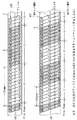
【図1】DV方式の記録フォーマットの説明に供する概念図である。
【図2】DV方式の記録フォーマットの説明に供する概念図である。
【図3】ディジタル8mm方式の記録フォーマットの説明に供する概念図である。
【図4】NTSC方式におけるDV方式及びディジタル8mm方式のATFフォーマットの説明に供する概念図である。
【図5】PAL方式におけるDV方式及びディジタル8mm方式のATFフォーマットの説明に供する概念図である。
【図6】NTSC方式におけるDVトラック番号並びに第1及び第2のパイロットフレーム信号と、パイロット信号の周波数との関係を示すタイミングチャートである。
【図7】PAL方式におけるDVトラック番号並びに第1及び第2のパイロットフレーム信号と、パイロット信号の周波数との関係を示すタイミングチャートである。
【図8】本実施の形態によるディジタルビデオカメラの構成を示すブロック図である。
【図9】図8に示すディジタルビデオカメラについて、NTSC方式におけるDVトラック番号並びに第1及び第2のパイロットフレーム信号と、パイロット信号の周波数との関係を示すタイミングチャートである。
【図10】図8に示すディジタルビデオカメラについて、PAL方式におけるDVトラック番号並びに第1及び第2のパイロットフレーム信号と、パイロット信号の周波数との関係を示すタイミングチャートである。
【符号の説明】
5、13……8mmテープ、7A、7B、12A、12B……磁気ヘッド、8……トラック、10……ディジタルビデオカメラ、15……コントロール部、19……信号処理部、D1……DVデータ、S1……映像信号、S2……音声信号、S7A、S7B……第1のパイロットフレーム信号、S8A、S8B……第2のパイロットフレーム信号、SWP……スイッチングパルス。[0001]
BACKGROUND OF THE INVENTION
The present invention relates to a magnetic recording apparatus and method and a magnetic recording / reproducing apparatus and method, and is suitable for application to a digital video camera, for example.
[0002]
[Prior art]
Conventionally, there is a DV (Digital Video) method (IEC 61834 helical scan digital video tape cassette recording system using 6.35mm magnetic tape for consumers (525 / 60,625 / 50,1125 / 60and1250 / 50systems)) as a recording method for digital video tape recorders. Recently, video cameras compatible with the DV system and stationary video tape recorders have appeared.
[0003]
In this DV system, the tape width of the magnetic tape to be used (hereinafter referred to as DV tape) is 6.35 [mm] (= 1/4 inch). For example, a recording system of a conventional analog video tape recorder is used. Tape width (8 [mm]) of magnetic tape (hereinafter referred to as 8mm tape) used in analog 8mm format (IEC 60843 helical scan video tape cassette recording system using 8mm magnet tape for consumer) It is narrower than.
[0004]
In spite of this, the DV system has an advantage that recording can be performed for a long time with high image quality because the video / audio signal to be recorded is compressed and the recording density is increased.
[0005]
[Problems to be solved by the invention]
By the way, although there is no compatibility between the DV system and the analog 8mm system, for example, if a video / audio signal of the DV data format can be recorded on an 8mm tape wider than the DV tape, the video / audio can be improved. It is possible to record the quality over a long period of time, and in addition to the analog 8mm system, it is considered that resources such as current 8mm tape production equipment and parts can be used effectively.
[0006]
Furthermore, if an analog 8mm playback function is provided, it is possible to enjoy past analog 8mm libraries and analog 8mm assets as they are.
[0007]
The present invention has been made in view of the above points, and an object of the present invention is to propose a magnetic recording apparatus and method, and a magnetic recording / reproducing apparatus and method capable of recording a video signal with high quality over a long period of time.
[0008]
[Means for Solving the Problems]
In order to solve such a problem, in the present invention, in a magnetic recording apparatus, recording data generating means for generating recording data in a data format corresponding to a predetermined digital recording method, and the recording data are divided into two tracks in the digital recording method. Recording means for sequentially recording the data as one track on the magnetic tape, and the recording data generating means outputs 1-bit control data indicating the frequency sequence of the pilot signal for each track on the magnetic tape in the NTSC format. In the frame period, PAL method, the value is inverted in one frame period and stored in the recording data.
[0009]
As a result, in this magnetic recording apparatus, the recording data of the data format corresponding to the digital recording system is recorded on the magnetic tape sequentially as two tracks in the digital recording system as one track successively, so that the video signal is of high quality. In addition, recording can be performed for a long time. In addition, when performing continuous shooting on the recording data recorded on the magnetic tape by the magnetic recording device, the recording data is recorded on each recorded track based on the value of the control data included in the recording data. It is possible to easily determine the frequency of the pilot signal to be added to the recording data to be newly recorded by splicing so that the arrangement of the pilot signal frequencies continues in a predetermined pattern.
[0010]
According to the present invention, in the magnetic recording method, a first step of generating recording data in a data format corresponding to a predetermined digital recording method, and the generated recording data are continuously provided for two tracks in the digital recording method. A second step of sequentially recording as one track on the magnetic tape, and in the first step, 1 bit of control data representing the frequency sequence of the pilot signal for each track on the magnetic tape is represented by 2 frames in the NTSC system. In the period and PAL method, the value is inverted in one frame period and stored in the recording data.
[0011]
As a result, according to this magnetic recording method, the recording data of the data format corresponding to the digital recording method is recorded on the magnetic tape sequentially by recording two tracks in the digital recording method as one track successively. It is possible to record the quality for a long time. In addition, when performing continuous shooting on the recording data recorded on the magnetic tape by this magnetic recording method, the recording data is recorded on each recorded track based on the value of the control data included in the recording data. It is possible to easily determine the frequency of the pilot signal to be added to the recording data to be newly recorded by splicing so that the arrangement of the pilot signal frequencies continues with a predetermined pattern.
[0012]
Further, in the present invention, in the magnetic recording / reproducing apparatus, recording data generating means for generating recording data in a data format corresponding to a predetermined digital recording system, and the recording data for two tracks in the digital recording system are continuously provided. Recording means for sequentially recording on the magnetic tape as one track, and the recording data generating means generates 1-bit control data representing the arrangement of the frequency of the pilot signal for each track on the magnetic tape; In the method, the value is inverted in one frame period and stored in the recording data.
[0013]
As a result, in this magnetic recording / reproducing apparatus, the recording signal of the data format corresponding to the digital recording system is recorded on the magnetic tape sequentially as two tracks in the digital recording system are continuously recorded as one track. In addition, recording can be performed for a long time. In addition, when the recording data recorded on the magnetic tape is taken by the magnetic recording / reproducing apparatus, the recording data is recorded on each recorded track based on the value of the control data included in the recording data. It is possible to easily determine the frequency of the pilot signal to be added to the recording data to be newly recorded by splicing so as to continue with a predetermined pattern of the frequency of the pilot signals.
[0014]
Further, in the present invention, in the magnetic recording / reproducing method, a first step of generating recording data in a data format corresponding to a predetermined digital recording method, and the generated recording data are continuously provided for two tracks in the digital recording method. And a second step of sequentially recording on the magnetic tape as one track. In the first step, 1-bit control data representing the frequency sequence of the pilot signal for each track on the magnetic tape is represented by 2 in the NTSC system. In the frame period, PAL method, the value is inverted in one frame period and stored in the recording data.
[0015]
As a result, according to this magnetic recording / reproducing method, the video signal is recorded by recording the recording data in the data format corresponding to the digital recording method on the magnetic tape in order by successively recording two tracks in the digital recording method as one track. High quality recording can be performed for a long time. In addition, when the recording data recorded on the magnetic tape is recorded by this magnetic recording / reproducing method, the recording data is recorded on each recorded track based on the value of the control data included in the recording data. It is possible to easily determine the frequency of the pilot signal to be added to the recording data to be newly recorded by splicing so that the arrangement of the pilot signal frequencies continues in a predetermined pattern.
[0016]
DETAILED DESCRIPTION OF THE INVENTION
Hereinafter, an embodiment of the present invention will be described in detail with reference to the drawings.
[0017]
(1) Recording method in this embodiment
Hereinafter, a recording system to which the present invention is applied will be described in comparison with a conventional DV system. The recording system to which the present invention is applied is a system for recording a video / audio signal having a DV data format (hereinafter referred to as DV data) on an 8 mm tape, and will be referred to as a digital 8 mm system in the following description. .
[0018]
First, in the DV system, as shown in FIG. 1, a
[0019]
In this case, two
[0020]
In the DV system, the
[0021]
Incidentally, FIG. 2 shows a data format in each
[0022]
And ITI area Ar 1 Stores various information related to tracks including pilot frame data, which will be described later, and an audio data area Ar. 2 And video data area Ar Three Each store audio data and video data, and subcode area Ar. Four Contains a subcode. Expansion area Ar Five And no data is recorded in IBG.
[0023]
Furthermore, in the DV system, the audio data area Ar 2 And video data area Ar Three Inside, two
[0024]
Therefore, for example, in the case of the NTSC system, data representing track pair numbers such as “0”, “0”, “1”, “1”... “5”, “5” in order from the
[0025]
Thus, in the DV system, it is possible to easily recognize on which
[0026]
On the other hand, in the digital 8 mm system to which the present invention is applied, as shown in FIG. In the PAL system, the arrow a at a rotational speed of 4500 [rpm] 2 The video / audio signal (DV data) in the DV data format is recorded while rotating in the direction.
[0027]
Also in this case, the
[0028]
Here, in the digital 8 mm system, DV data for two tracks in the DV system is continuously recorded on one
[0029]
For example, in the digital 8 mm system, the data of the odd track O1 and the data of the even track E2 in the DV system are continuously recorded as one
[0030]
Therefore, in the digital 8 mm system, video / audio data for one frame is recorded on an 8 mm tape divided into 5
[0031]
As described above, in the digital 8 mm system, data for two tracks in the DV system are continuously recorded in one
[0032]
(2) ATF format in digital 8mm format
Consider the ATF format in the digital 8 mm system as described above.
[0033]
First, in the DV system, 24/25 conversion is performed on every data to be recorded by inserting 1 extra bit for every 24 bits (3 bytes), thereby making it possible for ATF (Automatic Track Finding). A pilot signal of three frequencies is recorded on the entire track 4 (FIG. 1).
[0034]
Specifically, as shown in FIGS. 4A and 5A, in both cases of the NTSC system and the PAL system, for example, a pilot signal having a frequency f0 is recorded in the odd tracks O1, O3,. Then, pilot signals of frequencies f1, f2 are alternately recorded on the even tracks E2, E4,. Therefore, as a whole, pilot signals having frequencies of f0, f1, f0, f2 are repeated for each
[0035]
As a result, in the DV system, when the
[0036]
In the DV system, as apparent from FIGS. 4A and 5A, in the NTSC system (FIG. 4A), the ATF patterns are f0, f1, f0, f2, ... Or f0, f2, f0, f1,... In the PAL method (FIG. 5A), the ATF pattern is always f0, f1, f0, f2,.
[0037]
In the DV system, 1-bit control data called a pilot frame representing the arrangement of pilot signal frequencies in the frame is transferred to the ITI area Ar of each
[0038]
Therefore, in the DV system, the pilot frame data value repeats “0” and “1” for each frame in the NTSC system as shown in FIG. 4A, and the pilot frame data in the PAL system as shown in FIG. 5A. The value of is always “0”.
[0039]
On the other hand, in the digital 8 mm system, as described above, since one
[0040]
Therefore, in the present embodiment, as shown in FIGS. 4 (B) and 5 (B), as a digital 8 mm type ATF format, the pilot signal is f0 for each
[0041]
However, when such an ATF format is adopted for the digital 8 mm system, in the PAL system, the ATF pattern from the beginning of the frame is f0, f1, f0, f2... Or f0, f2, f0 as shown in FIG. , F1..., Whereas in the NTSC system, the ATF pattern from the beginning of the frame is f0, f1, f0, f2... Or f0, f2, f0, as shown in FIG. In addition to the case of f1,..., the case of f1, f0, f2, f0... and the case of f2, f0, f1, f0. In the DV system, the value of pilot frame data is not defined for such an ATF pattern.
[0042]
Therefore, in this embodiment, the value of the pilot frame data is set to “0” for the frames whose ATF patterns from the beginning are f0, f1, f0, f2... And f1, f0, f2, f0. The pilot frame data is recorded so that the value of the pilot frame data is set to “1” for the frames whose ATF patterns are from f0, f2, f0, f1... And f2, f0, f1, f0. To do.
[0043]
As a result, according to this method, “0” and “1” are repeated every two frames when the pilot frame data value is the NTSC system (FIG. 4B), and every one frame when the PAL system is used. “0” and “1” are repeated (FIG. 5B).
[0044]
In the digital 8 mm system, by recording the pilot frame data in this way, the frequency of the pilot signal at the time of splicing can be easily determined.
[0045]
That is, when pilot frame data is recorded as described above in the digital 8 mm system, the relationship between the pilot signal frequency and the pilot frame data value is as shown in FIG. 6 for the NTSC system and as shown in FIG. 7 for the PAL system. Become.
[0046]
6 and 7, FIGS. 6A and 7A show the switching pulse SWP at the time of recording and reproduction, and FIGS. 6B and 7B show the ATF pattern in the digital 8 mm system. Show. In addition, the numbers (0 to 9 in the case of the NTSC system, 0 to 9 in the case of the PAL system, A, and B) described below each frequency in FIGS. 6B and 7B are as follows. A serial number from the beginning of a frame assigned for convenience to DV data for one track in the DV system recorded on the
[0047]
Further, FIGS. 6C and 7C show a rectangular wave signal (hereinafter referred to as a first pilot frame signal) in which the value of pilot frame data in the digital 8 mm system recorded as described above is represented by a logical level. 6 (D) and 7 (D) show a rectangular wave signal (hereinafter referred to as a logical level) representing the value of track frame data given to DV data within each DV track number in the DV system. This is called a second pilot frame signal).
[0048]
The DV track number can be generated based on the above-mentioned track pair number included in each DV data in each digital 8
[0049]
6 and 7, when the ATF pattern correctly repeats f0, f1, f0, f2,..., The DV track number and the first track number in both the NTSC system and the PAL system. It can be seen that the frequency of the pilot signal is uniquely determined based on the logic level of the second pilot frame signal.
[0050]
Therefore, in the digital 8 mm system, by recording pilot frame data as described above, the DV of the video and audio (hereinafter referred to as the preceding video and audio) recorded on the 8 mm tape at the time of splice shooting. Based on the track pair number and pilot frame data values included in the data, a DV track number and first and second pilot frame signals are generated, and based on these, an ATF pattern is generated with respect to the ATF pattern of the preceding video and audio. f0, f1, f0, f2,... follow the pilot signal to be superimposed on each
[0051]
Then, in the digital 8 mm system, by sequentially superimposing the pilot signal having the frequency determined in this way on each
[0052]
(3) Configuration of digital video camera according to this embodiment
Here, FIG. 8 shows a digital video camera according to the present embodiment, in which two
[0053]
In other words, in the case of this
[0054]
At this time, the
[0055]
The
[0056]
Based on the switching pulse SWP supplied from the
[0057]
At this time, the erasing signal S3 is sent from the
[0058]
As a result, in the
[0059]
In this way, in the
[0060]
On the other hand, when the reproduction mode is selected by operating the
[0061]
As a result, each time the
[0062]
At this time, the
[0063]
At this time, the
[0064]
In this way, the
[0065]
(4) Specific processing of the control unit
Here, in the recording mode, the
[0066]
At this time, the
[0067]
When the
[0068]
In the case of this
[0069]
Therefore, the DV track number is generated in the
[0070]
In addition to the DV track number generation processing as described above, the
[0071]
Specifically, the
[0072]
Further, the
[0073]
Specifically, the
[0074]
Then, the
[0075]
In addition, the
[0076]
Further, the
[0077]
In the recording mode, for example, when a new 8
[0078]
At this time, the
[0079]
Then, the
[0080]
On the other hand, when DV data is recorded on the 8
[0081]
Therefore, the
[0082]
At this time, the
[0083]
In this manner, the
[0084]
(4) Operation and effect of the present embodiment
In the above configuration, in the
[0085]
Therefore, in this
[0086]
In this case, the
[0087]
Since the frequency of the pilot signal to be recorded on each track of the splicing video and audio can be easily determined in this way, the corresponding circuit configuration and program can be simplified.
[0088]
According to the above configuration, in the recording mode, DV data in the DV format is recorded on the 8
[0089]
(5) Other embodiments
In the above-described embodiment, the case where the present invention is applied to a digital video camera has been described. However, the present invention is not limited to this, and is not limited to a digital video camera, for example, a stationary digital video tape recorder. Can also be widely applied.
[0090]
In the above-described embodiment, the
[0091]
Further, in the above-described embodiment, the case where the present invention is applied to the
[0092]
In this case, recording data generating means for generating recording data and recording means for recording the recording data on the magnetic tape (in this embodiment, the
[0093]
【The invention's effect】
As described above, according to the present invention, recording data in a data format corresponding to a predetermined digital recording system is generated, and the recording data is recorded on the magnetic tape as two tracks in the digital recording system continuously as one track. By doing so, the video signal can be recorded with high quality for a long time. In this case, the control data representing the arrangement of the pilot signal frequencies for each track on the magnetic tape is stored in the recording data while inverting the value at the period of 2 frames in the NTSC system and at the period of 1 frame in the PAL system. Therefore, the frequency of the pilot signal to be added to the recording data to be newly recorded by the splicing to prevent the tracking from being deviated even at the boundary between the video based on the control data when the splicing is performed. Thus, a magnetic recording apparatus and method and a magnetic recording / reproducing apparatus and method that can simplify the determination of the corresponding circuit configuration and program can be realized.
[Brief description of the drawings]
FIG. 1 is a conceptual diagram for explaining a DV format recording format.
FIG. 2 is a conceptual diagram for explaining a DV format recording format;
FIG. 3 is a conceptual diagram for explaining a digital 8 mm recording format.
FIG. 4 is a conceptual diagram for explaining the DV format and the digital 8 mm format ATF format in the NTSC format.
FIG. 5 is a conceptual diagram for explaining the ATF format of the DV system and the digital 8 mm system in the PAL system.
FIG. 6 is a timing chart showing the relationship between the DV track number and the first and second pilot frame signals in the NTSC system and the frequency of the pilot signal.
FIG. 7 is a timing chart showing a relationship between a DV track number, first and second pilot frame signals in the PAL system, and a frequency of the pilot signal.
FIG. 8 is a block diagram showing a configuration of a digital video camera according to the present embodiment.
9 is a timing chart showing the relationship between the DV track number, the first and second pilot frame signals in the NTSC system, and the frequency of the pilot signal for the digital video camera shown in FIG. 8;
FIG. 10 is a timing chart showing the relationship between the DV track number, the first and second pilot frame signals in the PAL system, and the pilot signal frequency for the digital video camera shown in FIG. 8;
[Explanation of symbols]
5, 13: 8 mm tape, 7A, 7B, 12A, 12B: Magnetic head, 8: Track, 10: Digital video camera, 15: Control unit, 19: Signal processing unit, D1: DV data , S1... Video signal, S2... Audio signal, S7A, S7B... First pilot frame signal, S8A, S8B. Second pilot frame signal, SWP.
Claims (12)
上記記録データ生成手段により生成された上記記録データを、上記ディジタル記録方式における2トラック分を連続して1トラックとして磁気テープに順次記録する記録手段と
を具え、
上記記録データ生成手段は、
上記磁気テープにおける上記トラック毎の上記パイロット信号の周波数の並びを表す1ビットの制御データを、NTSC方式では2フレーム周期、PAL方式では1フレーム周期で値を反転させながら上記記録データ内に格納する
ことを特徴とする磁気記録装置。Recording data generating means for generating recording data in a data format corresponding to a predetermined digital recording system by performing predetermined signal processing including addition processing of a pilot signal for tracking control on a video signal;
Recording means for sequentially recording the recording data generated by the recording data generating means on a magnetic tape as two tracks in the digital recording system as one track continuously,
The recording data generation means includes
1-bit control data indicating the frequency sequence of the pilot signal for each track on the magnetic tape is stored in the recording data while inverting the value at a period of 2 frames in the NTSC system and at a period of 1 frame in the PAL system. A magnetic recording apparatus.
上記磁気テープは、アナログ8mm方式に応じたテープ幅の磁気テープでなる
ことを特徴とする請求項1に記載の磁気記録装置。The digital recording system is a digital video system,
2. The magnetic recording apparatus according to claim 1, wherein the magnetic tape is a magnetic tape having a tape width corresponding to an analog 8 mm system.
生成された上記記録データを、上記ディジタル記録方式における2トラック分を連続して1トラックとして磁気テープに順次記録する第2のステップと
を具え、
上記第1のステップでは、
上記磁気テープにおける上記トラック毎の上記パイロット信号の周波数の並びを表す1ビットの制御データを、NTSC方式では2フレーム周期、PAL方式では1フレーム周期で値を反転させながら上記記録データ内に格納する
ことを特徴とする磁気記録方法。A first step of generating recording data in a data format corresponding to a predetermined digital recording system by performing predetermined signal processing including addition processing of a pilot signal for tracking control on the video signal;
A second step of sequentially recording the generated recording data on a magnetic tape as two tracks in the digital recording system as one track continuously;
In the first step,
1-bit control data indicating the frequency sequence of the pilot signal for each track on the magnetic tape is stored in the recording data while inverting the value at a period of 2 frames in the NTSC system and at a period of 1 frame in the PAL system. A magnetic recording method.
上記磁気テープは、アナログ8mm方式に応じたテープ幅の磁気テープでなる
ことを特徴とする請求項3に記載の磁気記録方法。The digital recording system is a digital video system,
4. The magnetic recording method according to claim 3, wherein the magnetic tape is a magnetic tape having a tape width corresponding to an analog 8 mm system.
上記記録データ生成手段により生成された上記記録データを、上記ディジタル記録方式における2トラック分を連続して1トラックとして磁気テープに順次記録する記録手段と
を具え、
上記記録データ生成手段は、
上記磁気テープにおける上記トラック毎の上記パイロット信号の周波数の並びを表す1ビットの制御データを、NTSC方式では2フレーム周期、PAL方式では1フレーム周期で値を反転させながら上記記録データ内に格納する
ことを特徴とする磁気記録再生装置。Recording data generating means for generating recording data in a data format corresponding to a predetermined digital recording system so as to perform predetermined recording signal processing including addition processing of a pilot signal for tracking control on a video signal;
Recording means for sequentially recording the recording data generated by the recording data generating means on a magnetic tape as two tracks in the digital recording system as one track continuously,
The recording data generation means includes
1-bit control data indicating the frequency sequence of the pilot signal for each track on the magnetic tape is stored in the recording data while inverting the value at a period of 2 frames in the NTSC system and at a period of 1 frame in the PAL system. A magnetic recording / reproducing apparatus.
上記磁気テープは、アナログ8mm方式に応じたテープ幅の磁気テープでなる
ことを特徴とする請求項5に記載の磁気記録再生装置。The digital recording system is a digital video system,
6. The magnetic recording / reproducing apparatus according to claim 5, wherein the magnetic tape is a magnetic tape having a tape width corresponding to an analog 8 mm system.
上記再生手段により再生された上記記録データに含まれる上記制御データを抽出する制御データ抽出手段と、
上記制御手段と
を具え、
上記制御手段は、
上記磁気テープに先行して形成された上記トラック内の上記記録データを上記再生手段に再生させ、
当該再生された記録データに含まれる上記制御データを制御データ抽出手段に抽出させ、
上記映像信号に基づく上記記録データの記録時には、当該抽出された制御データに基づいて、上記磁気テープに先行して形成された上記トラックに記録された上記パイロット信号の上記周波数の並びと所定パターンで続くように、上記映像信号に基づく上記記録データに重畳すべき上記パイロット信号の上記周波数を順次決定し、
当該決定した上記周波数の上記パイロット信号を付加するようにして、上記映像信号に基づく上記記録データを生成するように上記記録データ生成手段を制御する
ことを特徴とする請求項5に記載の磁気記録再生装置。Reproducing means for reproducing the recorded data recorded on the magnetic tape;
Control data extracting means for extracting the control data contained in the recorded data reproduced by the reproducing means;
Comprising the above control means,
The control means includes
The reproducing means reproduces the recording data in the track formed in advance of the magnetic tape,
The control data extraction means extracts the control data included in the reproduced recording data,
At the time of recording the recording data based on the video signal, on the basis of the extracted control data, the frequency sequence of the pilot signal recorded on the track formed prior to the magnetic tape and a predetermined pattern are used. Next, sequentially determine the frequency of the pilot signal to be superimposed on the recording data based on the video signal,
6. The magnetic recording according to claim 5, wherein the recording data generating means is controlled to generate the recording data based on the video signal by adding the pilot signal of the determined frequency. Playback device.
を具えることを特徴とする請求項5に記載の磁気記録再生装置。A control data replacement means for replacing the control data contained in the recording data reproduced from the magnetic tape by the reproducing means with a value corresponding to the digital recording method and outputting the same to the outside. 5. The magnetic recording / reproducing apparatus according to 5.
生成された上記記録データを、上記ディジタル記録方式における2トラック分を連続して1トラックとして磁気テープに順次記録する第2のステップと
を具え、
上記第1のステップでは、
上記磁気テープにおける上記トラック毎の上記パイロット信号の周波数の並びを表す1ビットの制御データを、NTSC方式では2フレーム周期、PAL方式では1フレーム周期で値を反転させながら上記記録データ内に格納する
ことを特徴とする磁気記録再生方法。A first step of generating recording data of a data format corresponding to a predetermined digital recording system by performing predetermined recording signal processing including addition processing of a pilot signal for tracking control on the video signal;
A second step of sequentially recording the generated recording data on a magnetic tape as two tracks in the digital recording system as one track continuously;
In the first step,
1-bit control data indicating the frequency sequence of the pilot signal for each track on the magnetic tape is stored in the recording data while inverting the value at a period of 2 frames in the NTSC system and at a period of 1 frame in the PAL system. A magnetic recording / reproducing method.
上記磁気テープは、アナログ8mm方式に応じたテープ幅の磁気テープでなる
ことを特徴とする請求項9に記載の磁気記録再生方法。The digital recording system is a digital video system,
10. The magnetic recording / reproducing method according to claim 9, wherein the magnetic tape is a magnetic tape having a tape width corresponding to an analog 8 mm system.
上記磁気テープに先行して形成された上記トラック内の上記記録データを再生し、
当該再生された記録データに含まれる上記制御データを抽出し、
当該抽出された制御データに基づいて、上記磁気テープに先行して形成された各上記トラックに記録された上記パイロット信号の上記周波数の並びと所定パターンで続くように、上記映像信号に基づく上記記録データに付加すべき上記パイロット信号の上記周波数を順次決定し、
当該決定した周波数の上記パイロット信号を付加するようにして、上記映像信号に基づく記録データを生成する
ことを特徴とする請求項9に記載の磁気記録再生方法。In the first step,
Reproducing the recorded data in the track formed in advance of the magnetic tape,
Extracting the control data included in the reproduced recording data,
Based on the extracted control data, the recording based on the video signal is continued in a predetermined pattern with the frequency sequence of the pilot signals recorded on the tracks formed in advance on the magnetic tape. Sequentially determine the frequency of the pilot signal to be added to the data;
10. The magnetic recording / reproducing method according to claim 9, wherein recording data based on the video signal is generated by adding the pilot signal having the determined frequency.
上記再生した上記記録データに含まれる上記制御データを上記ディジタル記録方式に応じた値に差し替えて外部に出力する第4のステップと
を具えることを特徴とする請求項9に記載の磁気記録再生方法。A third step of reproducing the recording data based on the video signal from the magnetic tape;
10. The magnetic recording / reproducing method according to claim 9, further comprising: a fourth step of replacing the control data included in the reproduced recording data with a value corresponding to the digital recording method and outputting the value to the outside. Method.
Priority Applications (2)
| Application Number | Priority Date | Filing Date | Title |
|---|---|---|---|
| JP03747099A JP3877110B2 (en) | 1999-02-16 | 1999-02-16 | Magnetic recording apparatus and method, and magnetic recording / reproducing apparatus and method |
| US09/504,681 US6671455B1 (en) | 1999-02-16 | 2000-02-15 | Magnetic recording apparatus and method therefor, and magnetic recording and reproduction apparatus and method therefor |
Applications Claiming Priority (1)
| Application Number | Priority Date | Filing Date | Title |
|---|---|---|---|
| JP03747099A JP3877110B2 (en) | 1999-02-16 | 1999-02-16 | Magnetic recording apparatus and method, and magnetic recording / reproducing apparatus and method |
Publications (2)
| Publication Number | Publication Date |
|---|---|
| JP2000236517A JP2000236517A (en) | 2000-08-29 |
| JP3877110B2 true JP3877110B2 (en) | 2007-02-07 |
Family
ID=12498426
Family Applications (1)
| Application Number | Title | Priority Date | Filing Date |
|---|---|---|---|
| JP03747099A Expired - Fee Related JP3877110B2 (en) | 1999-02-16 | 1999-02-16 | Magnetic recording apparatus and method, and magnetic recording / reproducing apparatus and method |
Country Status (2)
| Country | Link |
|---|---|
| US (1) | US6671455B1 (en) |
| JP (1) | JP3877110B2 (en) |
Families Citing this family (1)
| Publication number | Priority date | Publication date | Assignee | Title |
|---|---|---|---|---|
| JP2005011456A (en) * | 2003-06-20 | 2005-01-13 | Sony Corp | Tape magnetic recording device |
Family Cites Families (7)
| Publication number | Priority date | Publication date | Assignee | Title |
|---|---|---|---|---|
| JPS59151348A (en) * | 1983-02-16 | 1984-08-29 | Sanyo Electric Co Ltd | Recording mode discriminating circuit |
| JPS6252752A (en) * | 1985-08-30 | 1987-03-07 | Sony Corp | Recording and reproducing device |
| AU591207B2 (en) * | 1985-12-23 | 1989-11-30 | Sony Corporation | Tracking control apparatus |
| JPS62164314A (en) * | 1986-01-14 | 1987-07-21 | Nippon Gakki Seizo Kk | Analog/digital converter |
| JPH03203062A (en) * | 1989-12-28 | 1991-09-04 | Sony Corp | Tracking controller |
| JP3237152B2 (en) * | 1991-11-15 | 2001-12-10 | ソニー株式会社 | Digital information signal recording device |
| JP3344117B2 (en) * | 1994-11-07 | 2002-11-11 | ソニー株式会社 | Phase control method and device |
-
1999
- 1999-02-16 JP JP03747099A patent/JP3877110B2/en not_active Expired - Fee Related
-
2000
- 2000-02-15 US US09/504,681 patent/US6671455B1/en not_active Expired - Fee Related
Also Published As
| Publication number | Publication date |
|---|---|
| JP2000236517A (en) | 2000-08-29 |
| US6671455B1 (en) | 2003-12-30 |
Similar Documents
| Publication | Publication Date | Title |
|---|---|---|
| US4819088A (en) | Magnetic recording and reproducing system | |
| US5404248A (en) | Video data recording/reproducing apparatus with efficient error correction | |
| JPH0375953B2 (en) | ||
| JPS58194162A (en) | Rotary head type magnetic recording and reproducing device | |
| JP3877110B2 (en) | Magnetic recording apparatus and method, and magnetic recording / reproducing apparatus and method | |
| KR100630243B1 (en) | Magnetic recording apparatus and method for digital signals, Magnetic reproduction apparatus and method for digital signals, Tape-type recording media | |
| EP0729149B1 (en) | Recording and/or reproducing digital signals | |
| KR100375487B1 (en) | Data stream recording/reproducing apparatus and recording/reproducing method | |
| KR20000023399A (en) | Method and apparatus for recording and/or reproducing digital signal and record medium of tape type | |
| US6031679A (en) | Magnetic recording/reproducing apparatus capable of reproducing digital data at minimum error rate | |
| KR100566353B1 (en) | Digital recorder with trick play operation | |
| JP3082715B2 (en) | Magnetic recording method, magnetic recording device, and magnetic recording medium | |
| JP3903654B2 (en) | Data transmission apparatus and data transmission method | |
| JPH0532952B2 (en) | ||
| JP4055096B2 (en) | Magnetic reproducing apparatus and method | |
| JP3094964B2 (en) | Magnetic recording method, magnetic recording device, magnetic recording medium, and magnetic transfer method | |
| JP4048460B2 (en) | Magnetic recording apparatus and method, magnetic reproducing apparatus and method, and tape-shaped recording medium | |
| KR100772081B1 (en) | Magnetic tape tracking control device and method, magnetic tape format, recording medium and program | |
| JPH11328783A (en) | Recording device | |
| JPH10162303A (en) | Magnetic recording device and magnetic recording and reproducing device | |
| JPH02174487A (en) | Video signal recorder | |
| JP2000182202A (en) | Magnetic recording apparatus and method, and magnetic reproducing apparatus and method | |
| JP2001054049A (en) | Data recording device and data recording method | |
| JP2000195028A (en) | Magnetic recording device and magnetic recording method | |
| JPS6363291A (en) | Circuit for stabilizing horizontal synchronized signal included in reproduced and modified composite video signal |
Legal Events
| Date | Code | Title | Description |
|---|---|---|---|
| A621 | Written request for application examination |
Free format text: JAPANESE INTERMEDIATE CODE: A621 Effective date: 20051130 |
|
| A977 | Report on retrieval |
Free format text: JAPANESE INTERMEDIATE CODE: A971007 Effective date: 20061005 |
|
| TRDD | Decision of grant or rejection written | ||
| A01 | Written decision to grant a patent or to grant a registration (utility model) |
Free format text: JAPANESE INTERMEDIATE CODE: A01 Effective date: 20061013 |
|
| A61 | First payment of annual fees (during grant procedure) |
Free format text: JAPANESE INTERMEDIATE CODE: A61 Effective date: 20061026 |
|
| LAPS | Cancellation because of no payment of annual fees |