JP3885687B2 - Blind device - Google Patents
Blind device Download PDFInfo
- Publication number
- JP3885687B2 JP3885687B2 JP2002241180A JP2002241180A JP3885687B2 JP 3885687 B2 JP3885687 B2 JP 3885687B2 JP 2002241180 A JP2002241180 A JP 2002241180A JP 2002241180 A JP2002241180 A JP 2002241180A JP 3885687 B2 JP3885687 B2 JP 3885687B2
- Authority
- JP
- Japan
- Prior art keywords
- blade
- link
- blades
- blind device
- puller
- Prior art date
- Legal status (The legal status is an assumption and is not a legal conclusion. Google has not performed a legal analysis and makes no representation as to the accuracy of the status listed.)
- Expired - Fee Related
Links
- 230000007246 mechanism Effects 0.000 claims description 122
- 210000000078 claw Anatomy 0.000 claims description 9
- 230000008878 coupling Effects 0.000 claims description 9
- 238000010168 coupling process Methods 0.000 claims description 9
- 238000005859 coupling reaction Methods 0.000 claims description 9
- 230000000630 rising effect Effects 0.000 claims description 2
- 238000010586 diagram Methods 0.000 description 6
- 238000005452 bending Methods 0.000 description 1
- 230000008602 contraction Effects 0.000 description 1
- 230000000694 effects Effects 0.000 description 1
- 210000003746 feather Anatomy 0.000 description 1
- 230000002093 peripheral effect Effects 0.000 description 1
Images





Landscapes
- Blinds (AREA)
- Emergency Lowering Means (AREA)
Description
【0001】
【発明の属する技術分野】
本発明は、建物の窓等の開口に配されて開口を目隠しするブラインド装置に関する。
【0002】
【発明が解決しようとする課題】
建物の窓等の開口に上下方向に複数の羽根(スラット)を配列して羽根の傾動でもって開口を開閉するようにしたブラインド装置は知られている。
【0003】
ところで、斯かるブラインド装置では、建物内の火災等の緊急時には開口を介して避難できるようにするために、開口に配されて開口を閉鎖している羽根を直ちに上下動できて、羽根に邪魔されずに開口を容易に開放できるようになっていることが好ましいのであるが、逆に、羽根を容易に上下動できるようになっていると、外部からも開口が開放される虞を有することになり、建物内への第三者の容易な侵入を許す結果となる。
【0004】
これに対処するために、建物内にロック機構(禁止機構)を設けて必要でない際には羽根を上下動できないようにしても、羽根を完全閉鎖ではなくて簾状に傾動させて配した場合には、羽根間の隙間を介して外部からロック機構が操作されてロックが解除される虞があり、ロック機構を設けた意味がなくなる。
【0005】
また、この種のブラインド装置では、羽根を完全閉鎖及び簾状閉鎖に選択的に配するために傾動機構が設けられるが、この傾動機構は、通常、玉チェーン、歯車機構を具備しており、歯車機構でもって意図しない傾動解除を防止している。
【0006】
ところで、傾動機構に玉チェーン、歯車機構を用いると、傾動、傾動解除に時間が掛かり、瞬時動作で傾動、傾動解除を行い難い。
【0007】
本発明は、前記諸点に鑑みてなされたものであって、その目的とするところは、建物内から開口を容易に開放できる一方、羽根が簾状に傾動されている場合であっても建物外から開口を開放できないようにしたブラインド装置を提供することにある。
【0008】
本発明の他の目的とするところは、一挙動で羽根の傾動、傾動解除を行い得て、建物内の火災等の緊急時における開口を介する避難を迅速にできるブラインド装置を提供することにある。
【0009】
【課題を解決するための手段】
本発明の第一の態様のブラインド装置は、開口に上下方向に配列されていると共に夫々が傾動自在であって上下動自在に配された複数の羽根と、この複数の羽根を相互に連結するリンク機構と、複数の羽根のうちの最上位の羽根を傾動させる傾動機構と、複数の羽根のうちの最下位の羽根の上昇を手動解除自在に禁止する禁止機構とを具備しており、ここで、リンク機構は、並置された一対のリンク部材を具備しており、傾動機構は、最上位の羽根を傾動させるように一対のリンク部材のうちの一方のリンク部材を弾性的に上方に付勢する弾性付勢機構と、最上位の羽根の傾動を解除させるように一対のリンク部材のうちの他方のリンク部材を手動で上昇させる手動上昇機構とを具備しており、禁止機構は、手動旋回により最下位の羽根の上昇を解除自在に禁止する旋回自在レバーを具備しており、旋回自在レバーは、傾動機構による最上位の羽根の傾動でもって一方のリンク部材を介して複数の羽根が簾状に配されている際には、最下位の羽根の上昇禁止を解除する方向への旋回が少なくとも最下位の羽根によって阻止されるようになっている一方、傾動機構による最上位の羽根の傾動の解除でもって他方のリンク部材を介して複数の羽根が開口を完全閉鎖するように配されている際には、最下位の羽根の上昇禁止を解除する方向への旋回が可能となっている。
【0010】
第一の態様のブラインド装置によれば、複数の羽根が簾状に配されている際には、最下位の羽根の上昇禁止を解除する方向への旋回自在レバーの旋回が少なくとも最下位の羽根によって阻止される、換言すれば、傾動された最下位の羽根でもって旋回自在レバーの旋回が邪魔されるために、羽根が簾状に配されている場合には建物外から禁止機構を禁止解除にできず、而して、開口を建物外から開放できず、しかも、複数の羽根が開口を完全閉鎖するように配されている際には、最下位の羽根の上昇禁止を解除する方向への旋回自在レバーの旋回が可能となっているために、建物内で開口を容易に開放できると共に、斯かる場合でも、複数の羽根が開口を完全閉鎖するように配されているために、建物外から禁止機構を禁止解除にできず、而して、開口を建物外からは開放できないことになる。
【0011】
本発明の第二の態様のブラインド装置では、第一の態様のブラインド装置において、禁止機構は、上下動自在であって旋回自在レバーが回転自在に支持されている横部材と、この横部材を最下位の羽根に連結する連結機構と、開口を規定する下枠に固着された係合部と、最下位の羽根の上昇禁止を解除する方向の旋回自在レバーの旋回でもって係合部への係合が解除される一方、旋回自在レバーのその逆の方向の旋回でもって係合部に係合するように旋回自在レバーに設けられた被係合部とを具備している。
【0012】
本発明の第三の態様のブラインド装置では、第二の態様のブラインド装置において、連結機構は、一端部が最下位の羽根の横端部側に連結されたベルトと、このベルトの他端部に一端部が連結されていると共に、他端部が横部材に連結されているばねとを具備しており、ばねは、最下位の羽根の横端部側を下方に弾性的に付勢しており、斯かる連結機構は、本発明の第四の態様のブラインド装置のように、ベルトの他端部の横部材に沿う横移動を案内する案内機構を更に具備しているとよい。
【0013】
本発明の第五の態様のブラインド装置は、開口に上下方向に配列されていると共に夫々が傾動自在であって上下動自在に配された複数の羽根と、この複数の羽根を相互に連結するリンク機構と、複数の羽根のうちの最上位の羽根を傾動させる傾動機構とを具備しており、ここで、リンク機構は、並置された一対のリンク部材を具備しており、傾動機構は、最上位の羽根を傾動させるように一対のリンク部材のうちの一方のリンク部材を弾性的に上方に付勢する弾性付勢機構と、最上位の羽根の傾動を解除させるように一対のリンク部材のうちの他方のリンク部材を手動で上昇させる手動上昇機構とを具備しており、手動上昇機構は、一端部で他方のリンク部材に連結された紐状体と、この紐状体の他端部に連結されていると共に係合部を有した引き手と、この引き手を回転自在であって上下動自在に支持すると共に、引き手の係合部に係合して弾性付勢機構の弾性力に起因する紐状体を介する引き手の上昇を阻止する被係合部を具備した引き手支持手段とを具備している。
【0014】
第五の態様のブラインド装置によれば、被係合部に対する係合部の手動による係合解除で、弾性付勢機構の弾性力に起因する紐状体を介する引き手の上昇を惹起することができる結果、一挙動で羽根の傾動を行い得て、建物内の火災等の緊急時における開口を介する避難を迅速にできる。
【0015】
第五の態様のブラインド装置において、引き手支持手段の被係合部は、好ましくは本発明の第六の態様のブラインド装置のように、上下方向に配列されている複数の凹所からなり、ここで、引き手の係合部は、凹所に嵌合する爪部からなり、斯かる凹所と爪部とからなる被係合部と係合部との場合、引き手は、好ましくは本発明の第七の態様のブラインド装置のように、紐状体の一端部が連結された手動操作部と、この手動操作部に一体的に設けられた軸部とを具備しており、ここで、係合部は軸部に一体的に設けられており、引き手支持手段は、開口を規定する縦枠に設けられていると共に、被係合部が設けられている支持本体と、この支持本体に上下方向に伸びて設けられていると共に、引き手の軸部が挿着されているスリットとを具備している。
【0016】
第五から第七のいずれかの態様のブラインド装置において、本発明の第八の態様のブラインド装置のように、紐状体はベルトからなり、傾動機構は、ベルトが掛け回されていると共に、ベルトを転向させる転向部を更に具備しているとよい。
【0017】
第五から第八のいずれかの態様のブラインド装置は、本発明の第九の態様のブラインド装置のように、複数の羽根のうちの最下位の羽根の上昇を手動解除自在に禁止する上述の禁止機構を更に具備しているとよく、この場合、禁止機構は、本発明の第十の態様のブラインド装置のように、上下動自在であって旋回自在レバーが回転自在に支持されている横部材と、この横部材を最下位の羽根に連結する連結機構と、開口を規定する下枠に固着された係合部と、最下位の羽根の上昇禁止を解除する方向の旋回自在レバーの旋回でもって係合部への係合が解除される一方、旋回自在レバーのその逆の方向の旋回でもって係合部に係合するように旋回自在レバーに設けられた被係合部とを具備しているとよく、第十の態様のブラインド装置において、連結機構は、好ましくは本発明の第十一の態様のブラインド装置のように、一端部が最下位の羽根の横端部側に連結されたベルトと、このベルトの他端部に一端部が連結されていると共に、他端部が横部材に連結されているばねとを具備しており、ここで、ばねは、最下位の羽根の横端部側を下方に弾性的に付勢しているとよく、斯かる連結機構は、好ましくは本発明の第十二の態様のブラインド装置のように、ベルトの他端部の横部材に沿う横移動を案内する案内機構を更に具備しているとよい。
【0018】
上記のいずれかの態様のブラインド装置において、好ましくは本発明の第十三の態様のブラインド装置のように、リンク機構は、各羽根の両横端部の夫々を支持する支持機構を更に具備しており、一対のリンク部材は、支持機構を介して複数の羽根を相互に連結しており、また上記のいずれかの態様のブラインド装置において、好ましくは本発明の第十四の態様のブラインド装置のように、各支持機構は、羽根に取り付けられた軸部材と、この軸部材に取り付けられたアーム部材とを具備しており、一対のリンク部材のうちの一方のリンク部材は、各アーム部材の一端部に連結されており、一対のリンク部材のうちの他方のリンク部材は、各アーム部材の他端部に連結されており、傾動機構は、最上位のアーム部材の一端部を上昇させて最上位の羽根を傾動させるようになっており、更にまた上記のいずれかの態様のブラインド装置において、好ましくは本発明の第十五の態様のブラインド装置のように、一対のリンク部材のうちの一方のリンク部材は、各羽根の前縁部に連結されており、一対のリンク部材のうちの他方のリンク部材は、各羽根の後縁部に連結されており、傾動機構は、最上位の羽根の前端部を上昇させて当該最上位の羽根を傾動させるようになっている。
【0019】
次に本発明及びその実施の形態を、図を参照して更に詳細に説明する。なお、本発明はこれら実施の形態に何等限定されないのである。
【0020】
【発明の実施の形態】
図1から図7において、本例のブラインド装置1は、開口2に上下方向A及びBに配列されていると共に夫々がR1方向に傾動自在であって上下動自在に配された複数の羽根3と、複数の羽根3を相互に連結するリンク機構4と、複数の羽根3のうちの最上位の羽根3を傾動させる傾動機構5と、複数の羽根3のうちの最下位の羽根3の上昇を手動解除自在に禁止する禁止機構6とを具備している。
【0021】
開口2は、相互に適宜の手段で固着された一対の中空の縦枠11及び12、上枠13並びに下枠14からなる枠機構15で規定されており、斯かる枠機構15は、集合住宅、戸建住宅等の建物の窓に取り付けられる。
【0022】
中空の各羽根3は、互いに平行に且つ横方向に伸びて開口2に配されており、図1に示すように、夫々の前縁部21及び後縁部22が上下方向A及びBに配列されることにより開口2を完全閉鎖し、図8に示すように、夫々の前縁部21及び後縁部22が前後方向に配列されることにより、簾状にされて開口2に配されるようになっている。
【0023】
リンク機構4は、各羽根3の両横端部25及び26の夫々を支持する支持機構27と、並置された一対のリンク部材28及び29とを具備している。
【0024】
縦枠11側の各羽根3の横端部25の夫々を支持する支持機構27と、縦枠12側の各羽根3の横端部26の夫々を支持する支持機構27とは、互いに同様に構成されているので、以下、縦枠11側の支持機構27を詳細に説明する。また、縦枠11内に配された一対のリンク部材28及び29と、縦枠12内に配された一対のリンク部材28及び29とは、同じく互いに同様に構成されているので、以下、縦枠11側の一対のリンク部材28及び29を詳細に説明する。
【0025】
各支持機構27は、特に図3に示すように、羽根3の横端部25に嵌装されて取り付けられた軸部材35と、軸部材35に取り付けられていると共に、縦枠11の内部に配されたアーム部材36とを具備しており、軸部材35は、羽根3の横端部25に嵌装された板部37と、板部37に一体成形されていると共に、アーム部材36に固着された軸部38とを具備しており、軸部38は、縦枠11に形成された上下方向A及びBに伸びるスリット39(特に図9参照)を通っており、軸部38が通るスリット39により、各支持機構27は、上下方向A及びBに移動自在であるが、前後方向、即ち、建物外40側及び建物内41側には移動できないようになっている。
【0026】
各アーム部材36は、特に図3に示すように、アーム本体51と、アーム本体51にねじ等により固着されたアーム板52と、アーム本体51及びアーム板52の両端部に回転自在に取り付けられた回転自在部材53及び54とを具備しており、回転自在部材53及び54の夫々にはスリット55が形成されている。
【0027】
リンク部材28は、各回転自在部材53に対して滑らないようにして各回転自在部材53のスリット55を通って伸びた可撓性の平ベルトからなっており、リンク部材29もまた、各回転自在部材54に対して滑らないようにして各回転自在部材54のスリット55を通って伸びた可撓性の平ベルトからなっており、リンク部材28は、最上位及び最下位のアーム部材36の回転自在部材53で終端しており、リンク部材29は、最上位及び最下位のアーム部材36の回転自在部材54で終端しており、こうして、リンク部材28は、各アーム部材36の一端部の回転自在部材53に連結されており、リンク部材29は、各アーム部材36の他端部の回転自在部材54に連結されており、而して、一対のリンク部材28及び29は、支持機構27を介して複数の羽根3を相互に連結している。
【0028】
傾動機構5は、最上位の羽根3をR1方向に傾動させるようにリンク部材28を弾性的に上方に付勢する弾性付勢機構62と、最上位の羽根3のR1方向の傾動を解除するようにリンク部材29を手動で上昇させる手動上昇機構61とを具備している。
【0029】
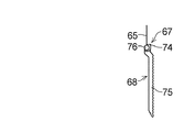
手動上昇機構61は、一端部64でリンク部材29に連結された紐状体65と、紐状体65の他端部66に連結されていると共に係合部67を有した引き手68と、引き手68を回転自在であって上下動自在に支持すると共に、引き手68の係合部67に係合して弾性付勢機構62の弾性力に起因する紐状体65を介する引き手68の上昇を阻止する被係合部69を具備した引き手支持手段70と、紐状体65が掛け回されていると共に、紐状体65を転向させる転向部71とを具備している。
【0030】
紐状体65は、リンク部材29の上端から一体的に延設された可撓性の平ベルトからなる。
【0031】
引き手68は、係合部67としての一対の爪部74に加えて、紐状体65の他端部66が連結された手動操作部75と、手動操作部75に一体的に設けられた一対の軸部76とを具備しており、各爪部74は、対応の軸部76に一体的に設けられている。
【0032】
引き手支持手段70は、開口2を規定する縦枠11に設けられていると共に、被係合部69が設けられている支持本体81と、上下方向に伸びて支持本体81の両側に設けられていると共に、引き手68の軸部76が挿着されているスリット82と、紐状体65の他端部66が通過するスリット83とを具備しており、支持本体81の開口80に、手動操作部75が上下方向A及びBに移動自在に嵌装されている。
【0033】
引き手68は、スリット82に挿着された軸部76を中心として図1に示すように下方に垂れ下げられた状態から建物内41側に張り出した状態に又はその逆の方向に手動で回動できるようになっている。
【0034】
被係合部69は、支持本体81の両側の内周面に上下方向に配列されている複数の凹所84からなり、引き手68の爪部74は、引き手68が図1に示すように下方に垂れ下げられた際に、凹所84の一つに嵌合するようになっている一方、引き手68が図1の二点鎖線で示すように建物内41側に回動された際に、凹所84の一つへの嵌合を解除するようになっており、而して、引き手68は、爪部74が凹所84のいずれにも嵌合されないように建物内41側に回動された際には、開口80及びスリット82に案内されて上下動自在となって、下方位置にある際には弾性付勢機構62の弾性力に起因して紐状体65を介して上昇され、上方位置にある際には弾性付勢機構62の弾性力に抗して手動により下方位置に引き下げることができる一方、下方位置から上方位置のいずれかの位置にあって、下方に垂れ下げられて爪部74が凹所84の一つに嵌合している際には、上下動できないようになっている。
【0035】
転向部71は縦枠11に取り付けられており、斯かる転向部71は、回転自在に縦枠11に取り付けられた複数のローラであってもよい。
【0036】
弾性付勢機構62は、一端部が最上位のアーム部材36の回転自在部材53に連結されていると共に、他端部が縦枠11に連結されているコイルばね91からなり、図1に示すように羽根3により開口2が完全閉鎖されている際には、伸長されて最上位のアーム部材36をR1方向に回動させるようにしており、引き手68が上方位置にある際には、図8に示すように縮められて羽根3を簾状に配するようにしている。
【0037】
傾動機構5は、爪部74の凹所84への嵌合を解除して引き手68を上下動自在にすることにより、コイルばね91の弾性力により最上位のアーム部材36をR1方向に回動させると共にリンク部材28を引き上げる一方、最上位のアーム部材36を介して紐状体65を引っ張ると共に、紐状体65を介して引き手68を上方位置に配し、而して、最上位のアーム部材36の一端部を上昇させて最上位の羽根3をR1方向に傾動させるようになっており、最上位の羽根3のR1方向の傾動でもってその他の羽根3をもまた、リンク部材28を介してR1方向に傾動させるようになっている一方、上方位置に配された引き手68をコイルばね91の弾性力に抗して手動により引き下げることにより、紐状体65を介して最上位のアーム部材36の一端部を上昇させて最上位の羽根3をR1方向と逆の方向に回動させ、これと共にリンク部材29を引き上げて他の羽根3もR1方向と逆の方向に回動させ、各羽根3の傾動を解除させるようになっている。
【0038】
禁止機構6は、手動旋回により最下位の羽根3の上昇を解除自在に禁止する旋回自在レバー101と、上下動自在であって旋回自在レバー101が回転自在に支持されている横部材102と、横部材102を最下位の羽根3に連結する連結機構103と、開口2を規定する下枠14に固着された係合部104と、最下位の羽根3の上昇禁止を解除する方向R2の旋回自在レバー101の旋回でもって係合部104への係合が解除される一方、旋回自在レバー101のその逆の方向の旋回でもって係合部104に係合するように旋回自在レバー101に設けられた被係合部105とを具備している。
【0039】
旋回自在レバー101は、軸111を介して横部材102の上部材112に回動自在に支持されており、横部材102は、上部材112に加えて、上部材112が一体的に固着された断面コ字状の本体113とを具備しており、縦枠11及び12間に配されている。
【0040】
連結機構103は、一端部121が最下位の羽根3の横端部25側に連結された可撓性のベルト122と、ベルト122の他端部123に一端部124が連結されていると共に、他端部125が横部材102の本体113に案内部材126を介して連結されているばね127と、ベルト122の他端部123の横部材102の本体113に沿う横移動を案内する案内機構128と、ベルト122を曲げ案内する案内部材129とを具備している。
【0041】
ベルト122は、その一端部121で軸ピン131を介して回転自在に最下位のアーム部材36の中央部に連結されており、こうして、ベルト122は、アーム部材36を介して最下位の羽根3の横端部25側に連結されている。
【0042】
ばね127はコイルばねからなっており、アーム部材36を下方に移動させるように、その弾性力によりベルト122を下方に引っ張っており、而して、最下位の羽根3の横端部25側を下方に弾性的に付勢している。
【0043】
案内機構128は、本体113に固着されていると共に、案内スリット135を有した案内部材136と、ベルト122の他端部123に取り付けられていると共に、案内スリット135に横移動自在に嵌合された可動駒137とを具備しており、ベルト122の引っ張りによるばね127の伸縮で可動駒137が案内スリット135に案内されることにより、ベルト122の他端部123の横移動を案内するようになっている。
【0044】
案内部材129は、その下面及び側面に溝141を有しており、一端部142では本体113内に嵌着されていると共に、他端部143ではスリット39及び縦枠11内に上下動自在に配されており、ベルト122は、溝141において案内部材129に摺動自在に接触しており、これによりベルト122は、案内部材129により曲げ案内されている。
【0045】
なお、連結機構103と同等の連結機構を縦枠12側に設けてもよい。
【0046】
下枠14に固着された係合部104は、被係合部105を受け入れる凹所145を有しており、被係合部105は、旋回自在レバー101に植設された突起からなる。
【0047】
禁止機構6では、旋回自在レバー101が図1及び図2に示すように横部材102に沿って配されて凹所145に被係合部105が受容され、係合部104と被係合部105との係合がなされている際には、横部材102が下枠14から離れて上昇することを阻止、而して、横部材102にばね127、ベルト122及び最下位の支持機構27を介して連結された最下位の羽根3の上昇を禁止し、旋回自在レバー101が図1の二点鎖線及び図9に示すようにR2方向に手動で旋回されて凹所145への被係合部105の受容が解除され、係合部104と被係合部105との係合が解除される際には、図10に示すように建物内41から手動により横部材102を下枠14から離れさせて上昇させることができるようになっている。
【0048】
また禁止機構6では、ばね127により最下位の羽根3を弾性的に下方に引っ張っているために、図1に示すように各羽根3の前縁部21及び後縁部22が上下方向A及びBに配列された場合でも、また図8に示すように各羽根3の前縁部21及び後縁部22が前後方向に配列された場合でも、羽根3を開口2に全体に亘って均等に配置できて、好ましく開口2を完全閉鎖又は簾状に閉鎖できる。
【0049】
旋回自在レバー101では、傾動機構5による最上位の羽根3のR1方向の傾動でもってリンク部材28を介して各羽根3が図8に示すように簾状に配されている際には、最下位の羽根3の上昇禁止についての手動解除を行う方向への旋回であるR2方向のその旋回が同じく図8に示すように最下位の羽根3によって阻止される、換言すれば邪魔されるようになっている一方、傾動機構5による最上位の羽根3のR1方向の傾動の手動解除でもってリンク部材28を介して羽根3が図1に示すように開口2を完全閉鎖するように配されている際には、最下位の羽根3の上昇禁止についての手動解除を行う方向への旋回であるR2方向のその旋回が最下位の羽根3によって邪魔されないで図9に示すように可能となっている。
【0050】
以上のようにブラインド装置1によれば、複数の羽根3が図8に示すように簾状に配されている際には手動解除を行う方向R2への旋回自在レバー101の旋回が最下位の羽根3によって阻止される、換言すれば、R1方向に傾動された最下位の羽根3でもって旋回自在レバー101の方向R2への旋回が邪魔されるために、羽根3が簾状に配されている場合には建物外40から禁止機構を禁止解除にできず、而して、開口2を建物外40から開放できず、しかも、図1及び図9に示すように複数の羽根3が開口2を完全閉鎖するように配されている際には手動解除を行う方向R2への旋回自在レバー101の旋回が可能となっているために、建物内41から開口2を容易に開放できると共に、斯かる場合でも、複数の羽根3が開口2を完全閉鎖するように配されているために、建物外40から禁止機構6を禁止解除にできず、而して、開口2を建物外40からは開放できないことになる。
【0051】
またブラインド装置1によれば、旋回自在レバー101により係合部104と被係合部105との係合を解除した後の傾動機構5における被係合部69に対する係合部67の手動による係合解除で、弾性付勢機構62の弾性力に起因する紐状体65を介する引き手68の上昇を惹起することができる結果、一挙動で羽根3の傾動を行い得て、建物内41の火災等の緊急時における開口2を介する避難を迅速にできる。
【0052】
ところで、上記のブラインド装置1では、支持機構27を介して各羽根3を連結したが、これに代えて、一方のリンク部材28を、各羽根3の前縁部21に直接に連結し、他方のリンク部材29を各羽根3の後縁部22に直接に連結してもよく、この場合、最上位の羽根3の後縁部22を直接に上昇させて当該最上位の羽根3の傾動を解除させるように傾動機構5を構成してもよい。
【0053】
【発明の効果】
本発明によれば、建物内から開口を容易に開放できる一方、羽根が簾状に傾動されている場合であっても建物外から開口を開放できないようにしたブラインド装置を提供することができる。
【0054】
また本発明によれば、一挙動で羽根の傾動、傾動解除を行い得て、建物内の火災等の緊急時における開口を介する避難を迅速にできるブラインド装置を提供することができる。
【図面の簡単な説明】
【図1】本発明の一実施態様の好ましい例の側面説明図である。
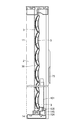
【図2】図1に示す例の正面説明図である。
【図3】図1に示す例の平面説明図である。
【図4】図1に示す例の一部平面説明図である。
【図5】図1に示す例の一部の詳細説明図である。
【図6】図1に示す例の一部の詳細説明図である。
【図7】図1に示す例の一部の詳細説明図である。
【図8】図1に示す例の動作説明図である。
【図9】図1に示す例の動作説明図である。
【図10】図1に示す例の動作説明図である。
【符号の説明】
1 ブラインド装置
2 開口
3 羽根
4 リンク機構
5 傾動機構
6 禁止機構[0001]
BACKGROUND OF THE INVENTION
The present invention relates to a blind device that is arranged in an opening such as a window of a building and blinds the opening.
[0002]
[Problems to be solved by the invention]
There is known a blind device in which a plurality of blades (slats) are arranged vertically in an opening such as a window of a building so that the opening is opened and closed by tilting the blade.
[0003]
By the way, in such a blind device, in order to be able to evacuate through an opening in the event of an emergency such as a fire in a building, the blades arranged in the opening and closing the opening can be moved up and down immediately, thereby obstructing the blade. It is preferable that the opening can be easily opened without being opened, but conversely, if the blade can be easily moved up and down, the opening may be opened from the outside. As a result, a third party can easily enter the building.
[0004]
In order to cope with this, when a lock mechanism (prohibition mechanism) is provided in the building so that the blade cannot be moved up and down when it is not necessary, the blade is tilted like a bowl instead of being completely closed. In this case, there is a possibility that the lock mechanism is operated from the outside through the gap between the blades and the lock is released.
[0005]
Further, in this type of blind device, a tilting mechanism is provided to selectively arrange the blades in the complete closure and the hook-like closure, and this tilting mechanism usually includes a ball chain and a gear mechanism. The gear mechanism prevents unintentional tilt release.
[0006]
By the way, when a ball chain or a gear mechanism is used for the tilting mechanism, it takes time to tilt and release the tilt, and it is difficult to tilt and release the tilt by an instantaneous operation.
[0007]
The present invention has been made in view of the above points, and the object of the present invention is to easily open the opening from the inside of the building, while the blades are tilted in a bowl shape. An object of the present invention is to provide a blind device in which the opening cannot be opened.
[0008]
Another object of the present invention is to provide a blind device that can perform the tilting and releasing of tilting of the blades in one behavior and can quickly evacuate through an opening in an emergency such as a fire in a building. .
[0009]
[Means for Solving the Problems]
In the blind device according to the first aspect of the present invention, a plurality of blades which are arranged in the opening in the vertical direction and are each tiltable and arranged to be movable up and down, and the plurality of blades are connected to each other. A link mechanism, a tilting mechanism that tilts the uppermost blade of the plurality of blades, and a prohibiting mechanism that prohibits the lifting of the lowermost blade of the plurality of blades so as to be manually releasable. The link mechanism includes a pair of juxtaposed link members, and the tilting mechanism elastically attaches one of the pair of link members upward so as to tilt the uppermost blade. An urging elastic urging mechanism and a manual raising mechanism for manually raising the other link member of the pair of link members so as to release the tilt of the uppermost blade. On the lowest blade by turning A pivot lever that releasably inhibits the pivot lever when the uppermost blade is tilted by the tilt mechanism and a plurality of blades are arranged in a bowl shape via one link member. The lowermost blade is prevented from turning in the direction of lifting the prohibition of the lowermost blade at least, while the lowermost blade prevents the uppermost blade from being tilted by the tilting mechanism. When the plurality of blades are arranged so as to completely close the opening via the member, it is possible to turn in the direction to release the prohibition of raising the lowest blade.
[0010]
According to the blind device of the first aspect, when the plurality of blades are arranged in a bowl shape, the swiveling of the swivel lever in the direction to release the prohibition of raising the lowest blade is at least the lowest blade. In other words, when the blades are arranged in a bowl shape, the prohibition mechanism is canceled from outside the building, because the pivoting lever is hindered by the tilted lowermost blade. Therefore, when the opening cannot be opened from the outside of the building, and when the plurality of blades are arranged so as to completely close the opening, the upward movement of the lowermost blade is released. Since the swivel lever can be swiveled, the opening can be easily opened in the building, and even in such a case, the plurality of blades are arranged so as to completely close the opening. The prohibition mechanism cannot be canceled from outside, Te, will not be able to open the opening from outside the building.
[0011]
In the blind device according to the second aspect of the present invention, in the blind device according to the first aspect, the prohibiting mechanism includes a lateral member that is movable up and down and a pivotable lever is rotatably supported. The connecting mechanism for connecting to the lowest blade, the engaging portion fixed to the lower frame defining the opening, and the swiveling lever in the direction for releasing the prohibition of raising the lowest blade to the engaging portion While being disengaged, it includes an engaged portion provided on the swivel lever so as to engage with the engagement portion by swiveling in the opposite direction of the swivel lever.
[0012]
In the blind device according to the third aspect of the present invention, in the blind device according to the second aspect, the connection mechanism includes a belt having one end connected to the lateral end of the lowest blade and the other end of the belt. And a spring having the other end connected to the horizontal member, and the spring elastically biases the horizontal end of the lowest blade downward. Such a coupling mechanism may further include a guide mechanism for guiding the lateral movement along the lateral member at the other end of the belt as in the blind device according to the fourth aspect of the present invention.
[0013]
A blind device according to a fifth aspect of the present invention connects a plurality of blades to each other and a plurality of blades arranged in the opening in the vertical direction and tiltable and vertically movable. A link mechanism and a tilt mechanism that tilts the uppermost blade of the plurality of blades, wherein the link mechanism includes a pair of link members arranged side by side; An elastic biasing mechanism that elastically biases one of the pair of link members upward so as to tilt the uppermost blade, and a pair of link members that release the tilt of the uppermost blade A manual lifting mechanism that manually lifts the other link member, and the manual lifting mechanism includes a string-like body connected to the other link member at one end, and the other end of the string-like body. And has an engaging part. A puller and a puller that supports the puller in a rotatable and vertically movable manner, and engages with an engaging portion of the puller and engages the puller via a string-like body caused by the elastic force of the elastic biasing mechanism. And a puller support means having an engaged portion for preventing the ascent.
[0014]
According to the blind device of the fifth aspect, the manual disengagement of the engaging portion with respect to the engaged portion causes the puller to rise through the string-like body due to the elastic force of the elastic biasing mechanism. As a result, the blade can be tilted with one behavior, and the evacuation through the opening in an emergency such as a fire in the building can be quickly performed.
[0015]
In the blind device of the fifth aspect, the engaged portion of the puller support means is preferably composed of a plurality of recesses arranged in the vertical direction as in the blind device of the sixth aspect of the present invention, Here, the engaging portion of the puller includes a claw portion that fits into the recess, and in the case of the engaged portion and the engaging portion including the recess and the claw portion, the puller is preferably As in the blind device according to the seventh aspect of the present invention, it comprises a manual operation part to which one end of the string-like body is connected, and a shaft part provided integrally with the manual operation part, The engaging portion is provided integrally with the shaft portion, and the puller support means is provided on the vertical frame that defines the opening, and the support main body provided with the engaged portion, The support body is provided with a slit extending in the vertical direction and into which the shaft portion of the puller is inserted. By that.
[0016]
In the blind device according to any one of the fifth to seventh aspects, like the blind device according to the eighth aspect of the present invention, the string-like body is composed of a belt, and the tilting mechanism has the belt wound around, It is preferable to further include a turning portion for turning the belt.
[0017]
The blind device according to any of the fifth to eighth aspects, as in the blind device according to the ninth aspect of the present invention, is configured to prohibit the ascent of the lowest blade among the plurality of blades from being manually released freely. It is preferable to further include a prohibiting mechanism. In this case, the prohibiting mechanism can move up and down like the blind device according to the tenth aspect of the present invention, and the lateral lever in which the pivotable lever is rotatably supported. A member, a coupling mechanism for connecting the transverse member to the lowest blade, an engaging portion fixed to a lower frame defining the opening, and a turn of the swivelable lever in a direction to release the prohibition of raising the lowest blade Thus, the engaging portion is disengaged from the engaging portion, and the engaged portion is provided on the swivel lever so as to be engaged with the engaging portion by swiveling in the opposite direction of the swivel lever. In the blind device of the tenth aspect, The connecting mechanism is preferably a belt whose one end is connected to the lateral end side of the lowest blade as in the blind device of the eleventh aspect of the present invention, and one end is connected to the other end of the belt. And a spring having the other end connected to the lateral member, wherein the spring elastically biases the lateral end of the lowest blade downward. Preferably, such a coupling mechanism further includes a guide mechanism for guiding the lateral movement along the transverse member at the other end of the belt, like the blind device according to the twelfth aspect of the present invention. Good.
[0018]
In the blind device of any of the above aspects, preferably the link mechanism further includes a support mechanism for supporting each of the lateral ends of each blade, as in the blind device of the thirteenth aspect of the present invention. The pair of link members interconnects a plurality of blades via a support mechanism, and in the blind device of any of the above aspects, preferably the blind device of the fourteenth aspect of the present invention As described above, each support mechanism includes a shaft member attached to the blade and an arm member attached to the shaft member, and one link member of the pair of link members is each arm member. The other link member of the pair of link members is connected to the other end of each arm member, and the tilting mechanism raises one end of the uppermost arm member. Best Further, in the blind device according to any one of the above aspects, preferably, as in the blind device according to the fifteenth aspect of the present invention, one of the pair of link members. The link member is connected to the front edge of each blade, the other link member of the pair of link members is connected to the rear edge of each blade, and the tilting mechanism is connected to the uppermost blade. The front end is raised to tilt the uppermost blade.
[0019]
Next, the present invention and its embodiments will be described in more detail with reference to the drawings. The present invention is not limited to these embodiments.
[0020]
DETAILED DESCRIPTION OF THE INVENTION
1 to 7, the
[0021]
The
[0022]
The
[0023]
The
[0024]
The
[0025]
As shown in FIG. 3, each
[0026]
As shown in FIG. 3 in particular, each
[0027]
The
[0028]
The
[0029]
The
[0030]
The string-
[0031]
The
[0032]
The puller support means 70 is provided on the
[0033]
As shown in FIG. 1, the
[0034]
The engaged
[0035]
The turning
[0036]
The
[0037]
The
[0038]
The prohibiting
[0039]
The
[0040]
The
[0041]
The
[0042]
The
[0043]
The
[0044]
The
[0045]
Note that a coupling mechanism equivalent to the
[0046]
The engaging
[0047]
In the prohibiting
[0048]
Further, in the prohibiting
[0049]
In the
[0050]
As described above, according to the
[0051]
Further, according to the
[0052]
By the way, in said
[0053]
【The invention's effect】
ADVANTAGE OF THE INVENTION According to this invention, while being able to open an opening easily from the inside of a building, even if it is a case where a blade | wing is tilted like a bowl, the blind apparatus which cannot open an opening from the outside of a building can be provided.
[0054]
Further, according to the present invention, it is possible to provide a blind device that can perform tilting and releasing tilting of the blades with a single behavior, and can quickly evacuate through an opening in an emergency such as a fire in a building.
[Brief description of the drawings]
FIG. 1 is an explanatory side view of a preferred example of an embodiment of the present invention.
2 is an explanatory front view of the example shown in FIG. 1. FIG.
FIG. 3 is an explanatory plan view of the example shown in FIG. 1;
FIG. 4 is a partial plan view of the example shown in FIG.
FIG. 5 is a detailed explanatory diagram of a part of the example shown in FIG. 1;
FIG. 6 is a detailed explanatory diagram of a part of the example shown in FIG. 1;
FIG. 7 is a detailed explanatory diagram of a part of the example shown in FIG. 1;
8 is an operation explanatory diagram of the example shown in FIG. 1. FIG.
FIG. 9 is an operation explanatory diagram of the example shown in FIG. 1;
10 is an operation explanatory diagram of the example shown in FIG. 1. FIG.
[Explanation of symbols]
1 Blind device
2 opening
3 feathers
4 Link mechanism
5 Tilt mechanism
6 Prohibition mechanism
Claims (15)
Priority Applications (1)
| Application Number | Priority Date | Filing Date | Title |
|---|---|---|---|
| JP2002241180A JP3885687B2 (en) | 2002-08-21 | 2002-08-21 | Blind device |
Applications Claiming Priority (1)
| Application Number | Priority Date | Filing Date | Title |
|---|---|---|---|
| JP2002241180A JP3885687B2 (en) | 2002-08-21 | 2002-08-21 | Blind device |
Publications (2)
| Publication Number | Publication Date |
|---|---|
| JP2004076503A JP2004076503A (en) | 2004-03-11 |
| JP3885687B2 true JP3885687B2 (en) | 2007-02-21 |
Family
ID=32023758
Family Applications (1)
| Application Number | Title | Priority Date | Filing Date |
|---|---|---|---|
| JP2002241180A Expired - Fee Related JP3885687B2 (en) | 2002-08-21 | 2002-08-21 | Blind device |
Country Status (1)
| Country | Link |
|---|---|
| JP (1) | JP3885687B2 (en) |
Families Citing this family (4)
| Publication number | Priority date | Publication date | Assignee | Title |
|---|---|---|---|---|
| JP4543727B2 (en) * | 2004-04-06 | 2010-09-15 | オイレスEco株式会社 | Opening and closing device |
| JP4876963B2 (en) * | 2007-02-20 | 2012-02-15 | オイレスEco株式会社 | Blind device |
| JP6056216B2 (en) * | 2012-06-28 | 2017-01-11 | オイレスEco株式会社 | Blind device |
| JP5953983B2 (en) * | 2012-06-28 | 2016-07-20 | オイレスEco株式会社 | Blind device |
-
2002
- 2002-08-21 JP JP2002241180A patent/JP3885687B2/en not_active Expired - Fee Related
Also Published As
| Publication number | Publication date |
|---|---|
| JP2004076503A (en) | 2004-03-11 |
Similar Documents
| Publication | Publication Date | Title |
|---|---|---|
| US7779886B2 (en) | Dual function mechanism for a Venetian blind | |
| CA2998010C (en) | Livestock head holder with singular operating lever for closing, unlocking and opening same | |
| JP3885687B2 (en) | Blind device | |
| TW201200707A (en) | Window opening and closing device | |
| JP4355630B2 (en) | Natural ventilation window locking device | |
| JPH031572Y2 (en) | ||
| JP3338419B2 (en) | Arm stopper device for lid of opening | |
| JP4879531B2 (en) | Natural ventilation window | |
| KR101496969B1 (en) | The emergency escaping apparatus for building | |
| JP5123156B2 (en) | Window equipment | |
| JP3741430B2 (en) | Window shield moving mechanism | |
| JP4470286B2 (en) | Blind device | |
| JP4560950B2 (en) | Blind device | |
| JPH0737032Y2 (en) | Blind lifting operation code | |
| JP4221259B2 (en) | Shutter for building opening | |
| JP4763024B2 (en) | Shutter for building opening | |
| JPH10317775A (en) | Upper hinge pin elevating device of door | |
| JP2001073610A (en) | Shutter for building opening part | |
| JPH0435495Y2 (en) | ||
| JP4555107B2 (en) | Folding door emergency opening device | |
| JP4431809B2 (en) | Blind device | |
| KR200191908Y1 (en) | Hoist car safety door of building | |
| JPH04122167U (en) | Midway release mechanism for vertical axis opening/closing windows | |
| JP4720012B2 (en) | Flip-up gate | |
| JPH06264663A (en) | Intermediate locking device of opening and closing of door |
Legal Events
| Date | Code | Title | Description |
|---|---|---|---|
| A711 | Notification of change in applicant |
Free format text: JAPANESE INTERMEDIATE CODE: A712 Effective date: 20040107 |
|
| A621 | Written request for application examination |
Free format text: JAPANESE INTERMEDIATE CODE: A621 Effective date: 20050729 |
|
| A977 | Report on retrieval |
Free format text: JAPANESE INTERMEDIATE CODE: A971007 Effective date: 20061025 |
|
| TRDD | Decision of grant or rejection written | ||
| A01 | Written decision to grant a patent or to grant a registration (utility model) |
Free format text: JAPANESE INTERMEDIATE CODE: A01 Effective date: 20061031 |
|
| A61 | First payment of annual fees (during grant procedure) |
Free format text: JAPANESE INTERMEDIATE CODE: A61 Effective date: 20061113 |
|
| R150 | Certificate of patent or registration of utility model |
Free format text: JAPANESE INTERMEDIATE CODE: R150 Ref document number: 3885687 Country of ref document: JP Free format text: JAPANESE INTERMEDIATE CODE: R150 |
|
| FPAY | Renewal fee payment (event date is renewal date of database) |
Free format text: PAYMENT UNTIL: 20091201 Year of fee payment: 3 |
|
| FPAY | Renewal fee payment (event date is renewal date of database) |
Free format text: PAYMENT UNTIL: 20101201 Year of fee payment: 4 |
|
| FPAY | Renewal fee payment (event date is renewal date of database) |
Free format text: PAYMENT UNTIL: 20111201 Year of fee payment: 5 |
|
| FPAY | Renewal fee payment (event date is renewal date of database) |
Free format text: PAYMENT UNTIL: 20121201 Year of fee payment: 6 |
|
| FPAY | Renewal fee payment (event date is renewal date of database) |
Free format text: PAYMENT UNTIL: 20121201 Year of fee payment: 6 |
|
| FPAY | Renewal fee payment (event date is renewal date of database) |
Free format text: PAYMENT UNTIL: 20131201 Year of fee payment: 7 |
|
| R250 | Receipt of annual fees |
Free format text: JAPANESE INTERMEDIATE CODE: R250 |
|
| R250 | Receipt of annual fees |
Free format text: JAPANESE INTERMEDIATE CODE: R250 |
|
| R250 | Receipt of annual fees |
Free format text: JAPANESE INTERMEDIATE CODE: R250 |
|
| R250 | Receipt of annual fees |
Free format text: JAPANESE INTERMEDIATE CODE: R250 |
|
| R250 | Receipt of annual fees |
Free format text: JAPANESE INTERMEDIATE CODE: R250 |
|
| R250 | Receipt of annual fees |
Free format text: JAPANESE INTERMEDIATE CODE: R250 |
|
| R250 | Receipt of annual fees |
Free format text: JAPANESE INTERMEDIATE CODE: R250 |
|
| R250 | Receipt of annual fees |
Free format text: JAPANESE INTERMEDIATE CODE: R250 |
|
| LAPS | Cancellation because of no payment of annual fees |