JP3889112B2 - Dam dam corridor and its construction method - Google Patents
Dam dam corridor and its construction method Download PDFInfo
- Publication number
- JP3889112B2 JP3889112B2 JP10120797A JP10120797A JP3889112B2 JP 3889112 B2 JP3889112 B2 JP 3889112B2 JP 10120797 A JP10120797 A JP 10120797A JP 10120797 A JP10120797 A JP 10120797A JP 3889112 B2 JP3889112 B2 JP 3889112B2
- Authority
- JP
- Japan
- Prior art keywords
- side wall
- cast
- dam
- concrete
- corridor
- Prior art date
- Legal status (The legal status is an assumption and is not a legal conclusion. Google has not performed a legal analysis and makes no representation as to the accuracy of the status listed.)
- Expired - Fee Related
Links
Images


Landscapes
- Forms Removed On Construction Sites Or Auxiliary Members Thereof (AREA)
Description
【0001】
【発明の属する技術分野】
この発明は、ダム堤体の通廊及びその施工法に関し、特に、予め工場生産した埋設型枠を用いて構築する通廊、及びこの埋設型枠を用いた通廊の施工法に関するものである。
【0002】
【従来の技術】
ダム堤体内には、保守点検や操作用通路、或は漏水の外部排水等のために通廊が縦横に巡らされている。この通廊は、従来一般に、堤体を構成する現場打ちコンクリートにより形成されている。このため、コンクリートの打込みに合せて、短時間で広範囲に亙って型枠を設置すると共に支保工をなす必要があった。一方、一部のダムにおいては、コンクリートブロックを積み上げることにより通廊を構成したり、ドーナツ状のプレキャストコンクリート部材を軸方向に連結して通廊を構成することが試みられている。
【0003】
【発明が解決しようとする課題】
しかしながら、型枠と支保工による在来工法によるときは、多数の熟練作業員を短期間に集中的に投入しなければならない。このため、人手不足の昨今、作業員の確保が困難である。また、現場打ちコンクリートを養生させる間、支保工を維持していなければならないので、通廊内部を資材の搬入や作業員の通行に利用することは出来ない。更に、一部の作業が遅れると全体の作業日程が影響を受け、工期の長期化やコストアップを招いている。
一方、コンクリートブロックを積み上げる工法や、プレキャストコンクリート部材を連結する工法では、現場打ちコンクリートとの一体化等、信頼性の点で問題があった。また、巨大なコンクリート部材を吊下げて設置作業を行なうため、大型クレーン等の重機が必要であった。
本発明は上記に鑑み提案されたもので、現場打ちコンクリートとのなじみが良好で信頼性の高い通廊を、簡単な施工により安価且つ短期間で提供することを目的とする。
【0004】
【課題を解決するための手段】
上記目的を達成するため、請求項1に記載した発明は、予め工場生産したコンクリート製の埋設型枠を、ダム建設現場において通行空間を確保するように組み立てて形成するダム堤体内に設ける通廊であって、埋設型枠は、天井部を形成する天井パネルと、側壁部を形成する側壁パネルとからなり、天井パネルの長さを側壁パネルの半分とし、前記両パネルの端部に隣接する埋設型枠と互に連結するための連結手段を備えると共に、現場打ちコンクリートとの接合面に付着処理部及び付着筋を備え、施工現場において、複数の埋設型枠を連結手段により連結して内部に通行空間を形成すると共に、周囲に現場打ちコンクリートを打ち込んで当該現場打ちコンクリートと一体化するダム堤体の通廊である。
また、請求項2に記載した発明は、予め工場生産したコンクリート製で付着処理部及び付着筋を備え、天井部を形成する天井パネルと、側壁部を形成する側壁パネルとからなり、天井パネルの長さを側壁パネルの半分とした埋設型枠を、ダム建設現場の所定位置に吊り込んで、内部に通行空間を確保するように組み立て、周囲に打設する現場打ちコンクリートの1リフト分に対応して内部に簡易支保工をなし、現場打ちコンクリートのリフトに対応して簡易支保工を順次移動させ、周囲の現場打ちコンクリートの打設が完了した後、簡易支保工を撤去して、埋設型枠と現場打ちコンクリートとを一体化するダム堤体の通廊の施工法である。
【0005】
【発明の実施の形態】
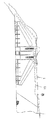
山間部に建設したダムの堤体1内には、完成後は保守点検のために、或は見学者の通路となり、一方建設中は作業員や機材の搬入路となる通廊11が縦横に巡らされている。この通廊11は水平面ばかりではなく、各階層を繋ぐ斜面に多くの場合は階段12として設けられ、更にエレベータ13も設けられている。尚、ダムの堤体1は、その構造により重力式、ロックフィル式、アーチ式等、種々の形式に分類されているが、何れの形式のダムであっても通廊11は必要である。
【0006】
従来、ダムの堤体1を建設するときは広範囲に亙ってコンクリートの打込を行なうので、通廊11を設けるためにはコンクリートの打込作業に合せて型枠を組み立てなければならず、作業員を短期間に集中的に投入する必要があった。一方、通廊11を開設したことにより堤体1の強度低下を招くことがあってはならないので、通廊11は堤体1と一体構造になって強度を確保していなければならない。
【0007】
本発明は、予め作製した埋設型枠を用いて、短期間で建設可能であると共に、充分な強度を発揮する通廊11を提供するものである。即ち、本発明の概要は、ダムの堤体1内に配設する通廊11を、軸方向に適宜な長さに分割すると共に、断面部においても適宜な部分に分割し、これらの分割した各部に対応して埋設型枠となるコンクリート部材を予め工場で生産し、このコンクリート製品を施工現場において組み立てて形成するようにしたものである。
【0008】
以下、本発明の一実施の形態を図面を参照して説明する。図面は、ダムの堤体1内に配設する通廊11を、断面部において天井部及び側壁部並びに底床部に分割し、底床部は現場打ちのコンクリートスラブを利用する場合を示している。
【0009】
即ち、図面に示す実施の形態では、天井部を形成するための天井パネル2(図5ないし図7参照)と、側壁部を形成するための側壁パネル3(図8ないし図9参照)とを、埋設型枠として予め作製している。尚、一例として、各パネルのサイズを示せば、側壁パネル3は長さ約3m、高さ約2.5mであって、鉄筋を含まない厚さは約6cm程度である。一方、天井パネル2は、ほゞ逆椀形の断面を有し、横幅は約3.1m、高さ約80cm、長さは側壁パネル3の半分の約1.5m程度である。このように、天井パネル2の長さを、側面パネルの半分とすれば、天井パネル2の重量を、側面の重量とほゞ合せることができ、同じクレーン等を使用して作業が可能となる。
【0010】
図2は、具体的な施工例を示す各パネルの割付図であり、この施工例では、二つの水平部11a,11bを階段部12aにより連絡させ、一方の水平部11aの端部には更にT字状に他の水平部11cが連絡すると共に、エレベータ13が設置してある。
【0011】
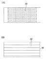
次に、個々のパネルについて具体的に説明する。先ず、通廊11の側壁部分を形成する側壁パネル3は、図8ないし図9に示すように、矩形のコンクリート製品であって、前記したように横幅×高さ×厚さが約300×250×6cm程度の大きさである。また、背面側(堤体1の内部に埋設される側)には、凹凸模様による付着処理部31を備えると共に、トラス状の付着筋32を備えている。
【0012】
一方、側壁パネル3の内部には、図8に破線で示すように、格子状に内部鉄筋33が配置され、この内部鉄筋33に上記付着筋32を構成するトラス筋の脚部32aが定着されている。
【0013】
また、側壁パネル3の所望の位置には、後述する支保工を付け止めるためのブラケット金具41を取り付けるための埋込ナット42が配置してある。即ち、図示の実施形態の場合は、上下方向に3段の支保工を取付可能なように、左右の側縁付近に沿って、夫々3個所に埋込ナット42を埋め込んでいる。
【0014】
更に、側壁パネル3の外縁部、即ち、上下の縁部及び左右の側縁部には、他のパネルまたは底床部と連結するための連結金具51を取り付けるための埋込ナット52を配置してある。例えば、図示の実施形態においては、上下縁部に沿って各々4個所、左右側縁には夫々上下2個所に埋め込んである。
【0015】
そして、側壁パネル3の上端面には、後述する天井パネル2と連結する際に、互に嵌合するように、段継状の継手部34が形成してある。
【0016】
尚、図示の実施形態においては、側壁パネル3の表面(通廊11の内部に露出する側)が平滑に仕上がるように打ち放ちとしているが、製造時に使用する型枠に凹凸模様を設けることにより、出来上がった側壁パネル3の表面に様々な意匠を施すことも可能である。
【0017】
上記のような側壁パネル3の上方に設置する天井パネル2は、図5ないし図7に示すように、上端部が縮幅した逆椀状である。即ち、対向する左右の側板部21の上縁から内向き斜めに斜板部22が延出し、この斜板部22の上縁がほゞ水平な天板部分23の各縁に連絡している。
【0018】
天井パネル2の外面側、即ちダム堤体1の内部に埋設される面には、付着処理を施して凹凸面24を設けると共に天板部分23には付着筋25を配設する。尚、図示していないが当該天井パネル2の内部には格子状に内部鉄筋が配筋してある。
【0019】
一方、通廊11の天井面となる内面側には、前記側壁パネル3と同様に製造時に凹凸模様を設けることにより、天井面に様々な意匠を施すことができる。
【0020】
上記のような天井パネル2の長さは、前記した側壁パネル3の例えば半分とすると、両パネルの重量バランスを図ることができ、共通の小型のクレーン等によって作業することが可能である。
【0021】
天井パネル2の側面の下端部には、前記した側壁パネル3の継手部34に対応する継手部26を形成する。また、連結金具51を取り付けるための埋込ナット27を所望の位置に配置しておく。
【0022】
通廊11の底床部分にも埋設型枠を用意してもよいが、図示の実施形態では堤体1を構築するために打ち込むコンクリートを利用して底床6を形成している。尚、底床6の端部には、排水用の側溝7を予め配置してからコンクリートを打ち込んでいる。
【0023】
上記側溝7は、例えばU字型の断面を有するコンクリート製品である所謂U字溝を連結して構成する。このU字溝の一例を図10に示すと、長さ約2m、高さ約36cm、溝の内法約30cm程度のものであり、壁体71内には鉄筋72が配置してある。また、U字溝の接続に際しては、端面に設けた凹部73にシール材74を充填するとよい。
【0024】
水平部分に形成する通廊11は、前記したような側壁パネル3と天井パネル2とを順次連結して形成する。一方、他の階層の通廊11と連結するため通廊11は、異る階層の間に傾斜状に設ける必要がある。そして、この傾斜する通廊11の底床6をスロープとしてもよいが、階段状に形成した方が短距離で高さの違いを吸収できるので効率的である。
【0025】
そこで、図示の実施の形態においては、階段部を形成するための階段ブロック8を用意している。即ち、図11ないし図13に示すように、1ブロックあたり、踏板81と蹴込板82とを5段あてに備える階段ブロック8を設けている。そして、この階段ブロック8の裏面側には付着処理を施して付着部83を形成すると共に、前縁部及び後縁部には段継手84、85を設けている。
【0026】
一方、階段ブロック8の一側縁には、前記した側壁パネル3を載せるための載置部86を形成する。一方、他の側縁には側溝7を臨ませ、該側溝7の外側側縁の上端面に側壁パネル3を載置するようにする。尚、図13に示すように、各連結部にはシール溝を形成すると共に、シール材87を充填して密着させるとよい。
【0027】
通廊11が分岐したり、方向を変える部分には、適宜角度のブロックを予め構成しておき、必要に応じて適宜組み合せるようにするとよい。例えば、90度、135度等を用意しておけばよい。
【0028】
前記したように、各パネルには鉄筋を配置する。即ち、埋設型枠の内部には内部鉄筋33を配設する。また、背面側には、堤体1と一体化するための付着筋25,32を配設する。更に、例えば図14に示すように、堤体1の構造材となる構造鉄筋9をパネルの周囲に配設し、上記付着筋25,32或は内部鉄筋33と定着させる。このように構成すれば、埋設型枠も構造材の一部となって堤体1の強度低下をきたすことがない。尚、配筋作業は、工場で予め行なうこともできるし、現場にて行なうこともできる。一方、上記構造鉄筋9を予め埋設型枠内に配設しておくこともできる。
【0029】
各パネルの連結には連結金具51を用いる。即ち、天井パネル2と側壁パネル3との連結には、両パネルの適宜位置に埋め込んだ埋込ナット27,52を利用して板状の連結金具51を取り付ける。また、側壁パネル3が底床6から立ち上がる部分は、上記と同じくパネルに埋め込んだ埋込ナット52を利用してL字型の固定金具53を取り付ける。更に、側壁パネル3の軸方向の延長についても、埋込ナット52を利用して板状の連結金具51を取り付ける。尚、各パネルの間にはシール材54を介在させる。
【0030】
通廊11の内部には、照明や通信用のケーブルを通し、或は空調用ダクトを設けるとよい。また、これらを背面側に埋め込むようにすることも可能である。
【0031】
次に、本発明に係るダム堤体の通廊11の施工法を説明する。先ず、底床6となるコンクリートを打設する。このとき、側溝7を予め埋め込む。
【0032】
所定の位置に側壁パネル3を対向させて起立させる。このとき、一方の側壁パネル3は側溝7の外側上端面に載置し、他の側壁パネル3は底床6の上面に載置する。そして、下縁部分に埋設した埋込ナット52を利用して取り付けたL字型の固定金具53を利用して底床6と連結する。また、コンクリートスラブに埋め込んだアンカー61と、適宜な高さ位置の付着筋32との間にステー62を斜めに張設する。更に、対向する側壁パネル3の上縁付近にパイプサポート43を介在させて間隔を保持する。このようにして、一対の側壁パネル3の設置を行なう(図15参照)。
【0033】
上記のようにして設置した側壁パネル3の外側に、コンクリートを打設する。このとき、コンクリートによる圧力に対抗するために、1リフト分、例えば75cmよりも若干下がった位置にパイプサポート43を配置する(図16参照)。
【0034】
尚、上記パイプサポート43は、図19に示すように、側壁パネル3に埋め込んだ埋込ナット42を利用して取り付けたアングル状のサポート金具44に桟木45を取り付け、この桟木45を介してパイプサポート先端のベースジャッキ46により保持する。
【0035】
第1リフトL1の打込が完了したら、第2リフトL2の打込に備えて、パイプサポート43を移動する。即ち、第1リフトL1に使用したパイプサポート43を第2リフトL2の上縁付近に上昇させるのである(図17参照)。このときも、前記と同様にサポート金具44及び桟木45を介在させる。そして、第2リフトL2の打込を行なう。
【0036】
次いで、第3リフトL3の打込に備えて支保工を行なうのであるが、第3リフトL3は側壁パネル3のほゞ上縁まで達するので、この支保工は最初に間隔保持のための配置したパイプサポート43で足りる(図18参照)。そして、第3リフトL3の打込を行なう。
【0037】
更に、天井パネル2を設置する。この天井パネル2は、前記したように下縁部分に継手部26が設けてあるので、この継手部26を側壁パネル3の継手部34に嵌合させると共に、連結金具51により止着する。
【0038】
一方、内側には支保工を実施する。即ち、図19に示すように、天井パネル2を下側から支えるジャッキ47及び幅方向に支えるパイプサポート43等を配置する。更に詳しく述べれば、天井パネル2の斜板部22をアングルピース48を介在させて支えると共に、天板部分23には桟木45を配置する。そして、Uヘッド47aに取り付けた大引き49を軸線方向に配置して上記桟木45を支持する。
【0039】
更に、この天井パネル2の長さは前記したように側壁パネル3の長さの半分であるので、天井パネル2を1枚の側壁パネル3あたり2枚配置する。そして、この天井パネル2同士を連結する際も連結金具51を利用する。
【0040】
天井パネル2の設置が終了したら、第4リフトのコンクリートを打ち込む。この第4リフトは天板部分23をほゞ埋設する高さとなる。
【0041】
一方、異る階層の通廊11を結ぶための階段部分においては、図20及び図21に示すように、支保工が多くなるが、前記した階段ブロック8を用いて上記した水平部と同様に施工することができる。尚、各ジャッキ47につなぎパイプ63及び根がらみパイプ64を架け渡して固定する。
【0042】
以上、本発明を図面の実施形態について説明したが、本発明は前記した実施形態に限定されるものではなく、特許請求の範囲に記載した構成を変更しない限り適宜に実施できる。
【0043】
【発明の効果】
本発明は、上記のように構成したので、以下のような効果を奏する。
施工がきわめて容易になる。即ち、予め工場生産した埋設型枠を順次組み立てて配置すればよいので、型枠大工や鉄筋工等、熟練技術者が不要となり、ボルト締め及び簡単な溶接ができれば、一般作業員で充分である。従って、熟練技術者が不足する昨今、人手不足の解消にきわめて有効である。
また、広範囲に亙って打込が必要なダムの堤体工事において、技術者を短期間に集中して投入する必要がないので、人手不足による工期の遅れがない。
しかも、埋設型枠であるのでコンクリートの保温効果を有し、山間部に建設されるダムにおいても理想的な養生状態とすることができ、また乾燥収縮を抑制することが可能で、コンクリートの持つ最大性能を発揮させることができる。
一方、型枠の解体が不要であると共に、設置後直ちに内部を利用可能になり、施工中も通廊を通行可能である。従って、カーテングラウチング資材機材の搬入をスムーズに行える。
通廊を適宜な形状に分割して数種類の分割形状のパネルないしブロックを用意し、これらのパネルないしブロックを組み合せて所望の形状の通廊を構成することができるので、少ない製作型枠で済み、コスト削減に有効であると共に、プレキャスト化のメリットも大きい。
更に、パネルないしブロックの表面に適宜な模様を形成することも容易なので、様々なデザイン或は意匠に対応することができ、特に見学者や観光客が通行可能な一般開放用通廊に適用した場合には、ダムのイメージアップに貢献することができる。
そして、支保工が簡単て、支保工部材数の大幅な軽減が可能であると共に、型枠組立作業の安全性が向上し、しかも小型クレーンで充分に作業可能である。
【図面の簡単な説明】
【図1】本発明に係る通廊を適用するダムの堤体の略図である。
【図2】通廊の割付を示す平面図及び側面図である。
【図3】通廊の断面図である。
【図4】側壁パネルと天井パネルとを組付けた側面図である。
【図5】天井パネルの正面図である。
【図6】天井パネルの平面図である。
【図7】天井パネルの側面図である。
【図8】側壁パネルの内面側を示す正面図及び側面図である。
【図9】側壁パネルの外面側を示す背面図及び底面図である。
【図10】側溝を示す正面図及び側面図、断面を示す正面図及び側面図、並びに連結部分の詳細図である。
【図11】階段ブロックを示す平面図及び側面図である。
【図12】階段ブロックを示す裏面図及び正面図である。
【図13】階段ブロックと側溝及び側壁パネルとの連結状態の説明図である。
【図14】支保工及び構造鉄筋の配置状態を示す通廊の正面図である。
【図15】通廊の施工法を示す説明図である。
【図16】通廊の施工法を示す説明図である。
【図17】通廊の施工法を示す説明図である。
【図18】通廊の施工法を示す説明図である。
【図19】通廊の施工法を示す説明図である。
【図20】階段部分の施工法を示す説明図である。
【図21】図20におけるA線に沿った断面図である。
【符号の説明】
1 堤体
2 天井パネル
3 側壁パネル
7 側溝
8 階段ブロック
11 通廊
24 凹凸面
25 付着筋
26 継手部
31 付着処理部
32 付着筋
34 継手部
43 パイプサポート
47 ジャッキ[0001]
BACKGROUND OF THE INVENTION
The present invention relates to a dam embankment corridor and a construction method thereof, and more particularly, to a corridor constructed using a prefabricated embedded formwork and a construction method of the corridor using the buried formwork. .
[0002]
[Prior art]
Inside the dam body, there are vertical and horizontal corridors for maintenance and inspection, operation passages, or external drainage of leaked water. The corridor is generally formed of cast-in-place concrete that constitutes a bank body. For this reason, it was necessary to install the formwork over a wide range in a short time and to perform support work in accordance with the concrete driving. On the other hand, in some dams, attempts have been made to construct a corridor by stacking concrete blocks, or to construct a corridor by connecting donut-shaped precast concrete members in the axial direction.
[0003]
[Problems to be solved by the invention]
However, when using the conventional method of formwork and support, a large number of skilled workers must be concentrated in a short period of time. For this reason, it is difficult to secure workers in the recent shortage of manpower. In addition, the support work must be maintained while curing the cast-in-place concrete, so the interior of the corridor cannot be used for carrying materials or passing workers. Furthermore, if a part of work is delayed, the whole work schedule is affected, resulting in a longer construction period and cost increase.
On the other hand, the method of stacking concrete blocks and the method of connecting precast concrete members have problems in terms of reliability such as integration with cast-in-place concrete. Moreover, in order to perform installation work by suspending a huge concrete member, a heavy machine such as a large crane is required.
The present invention has been proposed in view of the above, and it is an object of the present invention to provide a corridor that is well-suited with on-site concrete and has high reliability at a low cost and in a short period of time by simple construction.
[0004]
[Means for Solving the Problems]
In order to achieve the above-mentioned object, the invention described in
Moreover, the invention described in
[0005]
DETAILED DESCRIPTION OF THE INVENTION
In the
[0006]
Conventionally, when constructing the
[0007]
The present invention provides a
[0008]
Hereinafter, an embodiment of the present invention will be described with reference to the drawings. The drawing shows a case where the
[0009]
That is, in the embodiment shown in the drawings, a ceiling panel 2 (see FIGS. 5 to 7) for forming a ceiling portion and a side wall panel 3 (see FIGS. 8 to 9) for forming a side wall portion are provided. It has been prepared in advance as an embedded formwork. As an example, if the size of each panel is shown, the
[0010]
FIG. 2 is an allocation diagram of each panel showing a specific construction example. In this construction example, two
[0011]
Next, each panel will be specifically described. First, the
[0012]
On the other hand, inside the
[0013]
Further, an embedded
[0014]
Further, embedded
[0015]
And the
[0016]
In the illustrated embodiment, the surface of the side wall panel 3 (side exposed to the inside of the corridor 11) is laid out so as to be finished smoothly, but by providing a concavo-convex pattern on the formwork used during manufacture. Various designs can be applied to the surface of the completed
[0017]
As shown in FIGS. 5 to 7, the
[0018]
On the outer surface side of the
[0019]
On the other hand, on the inner surface side that becomes the ceiling surface of the
[0020]
When the length of the
[0021]
A
[0022]
Although an embedded formwork may be prepared for the bottom floor portion of the
[0023]
The
[0024]
The
[0025]
Therefore, in the illustrated embodiment, a
[0026]
On the other hand, on one side edge of the
[0027]
An appropriate angle block may be preliminarily configured at a portion where the
[0028]
As described above, reinforcing bars are arranged on each panel. That is, the
[0029]
A connection fitting 51 is used to connect the panels. That is, for connecting the
[0030]
The
[0031]
Next, the construction method of the
[0032]
The
[0033]
Concrete is placed outside the
[0034]
As shown in FIG. 19, the
[0035]
When driving of the first lift L1 is completed, the
[0036]
Next, a support work is performed in preparation for driving the third lift L3. Since the third lift L3 reaches almost the upper edge of the
[0037]
Furthermore, the
[0038]
On the other hand, support work will be carried out inside. That is, as shown in FIG. 19, a
[0039]
Furthermore, since the length of the
[0040]
When the installation of the
[0041]
On the other hand, as shown in FIGS. 20 and 21, in the staircase portion for connecting the
[0042]
As mentioned above, although embodiment of drawing was described for this invention, this invention is not limited to above-described embodiment, It can implement suitably, unless the structure described in the claim is changed.
[0043]
【The invention's effect】
Since the present invention is configured as described above, the following effects can be obtained.
Construction becomes extremely easy. That is, since it is sufficient to sequentially assemble and arrange the embedded formwork produced in the factory in advance, it is not necessary for skilled technicians such as formwork carpenters and rebar workers, and ordinary workers are sufficient if bolt tightening and simple welding are possible. . Therefore, it is extremely effective in resolving the shortage of labor due to the shortage of skilled engineers.
Moreover, in the construction of a dam body that needs to be driven over a wide area, it is not necessary to concentrate engineers in a short period of time, so there is no delay in the construction period due to lack of manpower.
Moreover, because it is a buried formwork, it has the effect of keeping concrete warm, it can be in an ideal curing state even in a dam constructed in a mountainous area, and it can suppress drying shrinkage. Maximum performance can be demonstrated.
On the other hand, it is not necessary to dismantle the formwork, and the interior can be used immediately after installation, and can pass through the corridor even during construction. Therefore, it is possible to smoothly carry in the curtain grouting material equipment.
By dividing the corridor into appropriate shapes, several types of divided panels or blocks can be prepared, and these panels or blocks can be combined to form the desired shape of the corridor. In addition to being effective in reducing costs, the benefits of precasting are also significant.
Furthermore, since it is easy to form an appropriate pattern on the surface of the panel or block, it can be applied to various designs or designs, and is especially applied to general open corridors that can be visited by visitors and tourists. In some cases, it can contribute to improving the image of the dam.
The support work is simple, the number of support work members can be greatly reduced, the safety of the formwork assembly work is improved, and the work can be sufficiently performed with a small crane.
[Brief description of the drawings]
FIG. 1 is a schematic view of a dam body to which a corridor according to the present invention is applied.
FIGS. 2A and 2B are a plan view and a side view showing allocation of a corridor.
FIG. 3 is a cross-sectional view of a corridor.
FIG. 4 is a side view in which a side wall panel and a ceiling panel are assembled.
FIG. 5 is a front view of a ceiling panel.
FIG. 6 is a plan view of a ceiling panel.
FIG. 7 is a side view of a ceiling panel.
FIGS. 8A and 8B are a front view and a side view showing an inner surface side of the side wall panel. FIGS.
FIGS. 9A and 9B are a rear view and a bottom view showing the outer surface side of the side wall panel. FIGS.
FIG. 10 is a front view and a side view showing a side groove, a front view and a side view showing a cross section, and a detailed view of a connecting portion.
FIG. 11 is a plan view and a side view showing a staircase block.
FIG. 12 is a back view and a front view showing a staircase block.
FIG. 13 is an explanatory diagram of a connection state between the stair block, the side groove, and the side wall panel.
FIG. 14 is a front view of a corridor showing the arrangement of support works and structural reinforcing bars.
FIG. 15 is an explanatory view showing a construction method of a corridor.
FIG. 16 is an explanatory view showing a construction method of a corridor.
FIG. 17 is an explanatory view showing a construction method of a corridor.
FIG. 18 is an explanatory view showing a construction method of a corridor.
FIG. 19 is an explanatory view showing a construction method of a corridor.
FIG. 20 is an explanatory diagram showing a construction method for a staircase portion.
21 is a cross-sectional view taken along line A in FIG.
[Explanation of symbols]
DESCRIPTION OF
Claims (2)
埋設型枠は、天井部を形成する天井パネルと、側壁部を形成する側壁パネルとからなり、天井パネルの長さを側壁パネルの半分とし、前記両パネルの端部に隣接する埋設型枠と互に連結するための連結手段を備えると共に、現場打ちコンクリートとの接合面に付着処理部及び付着筋を備え、施工現場において、複数の埋設型枠を連結手段により連結して内部に通行空間を形成すると共に、周囲に現場打ちコンクリートを打ち込んで当該現場打ちコンクリートと一体化することを特徴とするダム堤体の通廊。A corridor provided in a dam embankment formed by assembling a concrete embedded formwork produced in advance in a factory so as to secure a passage space at a dam construction site,
The embedded form consists of a ceiling panel that forms the ceiling part and a side wall panel that forms the side wall part, and the length of the ceiling panel is half of the side wall panel, and the embedded form form adjacent to the end parts of the two panels. In addition to providing connecting means for connecting to each other, an adhesion processing portion and an adhesion bar are provided on the joint surface with the cast-in-place concrete, and a plurality of embedded molds are connected by the connecting means on the construction site to provide a passage space inside. A dam embankment corridor characterized by being formed and cast with cast-in-place concrete around it and integrated with the cast-in-place concrete.
Priority Applications (1)
| Application Number | Priority Date | Filing Date | Title |
|---|---|---|---|
| JP10120797A JP3889112B2 (en) | 1997-04-18 | 1997-04-18 | Dam dam corridor and its construction method |
Applications Claiming Priority (1)
| Application Number | Priority Date | Filing Date | Title |
|---|---|---|---|
| JP10120797A JP3889112B2 (en) | 1997-04-18 | 1997-04-18 | Dam dam corridor and its construction method |
Publications (2)
| Publication Number | Publication Date |
|---|---|
| JPH10292353A JPH10292353A (en) | 1998-11-04 |
| JP3889112B2 true JP3889112B2 (en) | 2007-03-07 |
Family
ID=14294487
Family Applications (1)
| Application Number | Title | Priority Date | Filing Date |
|---|---|---|---|
| JP10120797A Expired - Fee Related JP3889112B2 (en) | 1997-04-18 | 1997-04-18 | Dam dam corridor and its construction method |
Country Status (1)
| Country | Link |
|---|---|
| JP (1) | JP3889112B2 (en) |
-
1997
- 1997-04-18 JP JP10120797A patent/JP3889112B2/en not_active Expired - Fee Related
Also Published As
| Publication number | Publication date |
|---|---|
| JPH10292353A (en) | 1998-11-04 |
Similar Documents
| Publication | Publication Date | Title |
|---|---|---|
| RU2418917C2 (en) | Structural elements and methods of their application | |
| US7958687B2 (en) | Concrete panel construction system | |
| CA2051393C (en) | A fire-resistant prefabricated steel beam | |
| US3678638A (en) | Building construction of modular units with settable material therebetween | |
| KR102263295B1 (en) | Double wall structure with flip type stopper and construction method | |
| CN108222291B (en) | Tensioning and anchoring method connection type assembled wall-plate structure and installation method | |
| CN110612373A (en) | Prefabricated pre-decorated volume construction of buildings | |
| JP2004528497A (en) | Reinforced building panels and triangular columns | |
| AU2018228650B2 (en) | Aerated concrete-hybrid construction element | |
| KR20050054407A (en) | Steel concrete structure using angle shapes | |
| KR20210069209A (en) | Precast Concrete Panel for exterior wall and construction method | |
| US20090301011A1 (en) | Reinforced concrete ceiling and process for the manufacture thereof | |
| RU2467134C2 (en) | System of panel construction and appropriate method | |
| US3600862A (en) | Procedure and precast building elements made of concrete or reinforced concrete for the construction of buildings or skeletons | |
| CN110778154A (en) | Integral prefabricated toilet | |
| JP3889112B2 (en) | Dam dam corridor and its construction method | |
| JPH09195438A (en) | Reinforced structures for precast concrete boards and buildings | |
| CN104652662B (en) | Prefabricated panel system | |
| CN214531897U (en) | Supporting system for construction of assembled prestressed hollow slab floor | |
| JP3961116B2 (en) | Floor structure in steel-frame building | |
| KR101086058B1 (en) | Building floor unit and floor construction method using the same | |
| KR930012072B1 (en) | Complex wire panels | |
| KR20210077872A (en) | Wall and floor construction method formed in a double structure | |
| JP2001003338A (en) | Construction method of railing of dam embankment and precast concrete railing member for dam embankment | |
| CA1296916C (en) | Structural panel and method of forming same |
Legal Events
| Date | Code | Title | Description |
|---|---|---|---|
| A521 | Written amendment |
Free format text: JAPANESE INTERMEDIATE CODE: A821 Effective date: 20040225 |
|
| A621 | Written request for application examination |
Free format text: JAPANESE INTERMEDIATE CODE: A621 Effective date: 20040225 |
|
| RD02 | Notification of acceptance of power of attorney |
Free format text: JAPANESE INTERMEDIATE CODE: A7422 Effective date: 20040225 |
|
| A977 | Report on retrieval |
Free format text: JAPANESE INTERMEDIATE CODE: A971007 Effective date: 20060424 |
|
| A131 | Notification of reasons for refusal |
Free format text: JAPANESE INTERMEDIATE CODE: A131 Effective date: 20060627 |
|
| A521 | Written amendment |
Free format text: JAPANESE INTERMEDIATE CODE: A523 Effective date: 20060825 |
|
| TRDD | Decision of grant or rejection written | ||
| A01 | Written decision to grant a patent or to grant a registration (utility model) |
Free format text: JAPANESE INTERMEDIATE CODE: A01 Effective date: 20061031 |
|
| A61 | First payment of annual fees (during grant procedure) |
Free format text: JAPANESE INTERMEDIATE CODE: A61 Effective date: 20061129 |
|
| R150 | Certificate of patent or registration of utility model |
Free format text: JAPANESE INTERMEDIATE CODE: R150 |
|
| LAPS | Cancellation because of no payment of annual fees |