JP3895112B2 - Combustion device - Google Patents
Combustion device Download PDFInfo
- Publication number
- JP3895112B2 JP3895112B2 JP2001013030A JP2001013030A JP3895112B2 JP 3895112 B2 JP3895112 B2 JP 3895112B2 JP 2001013030 A JP2001013030 A JP 2001013030A JP 2001013030 A JP2001013030 A JP 2001013030A JP 3895112 B2 JP3895112 B2 JP 3895112B2
- Authority
- JP
- Japan
- Prior art keywords
- gas
- raw fuel
- combustion
- mixing chamber
- fuel cell
- Prior art date
- Legal status (The legal status is an assumption and is not a legal conclusion. Google has not performed a legal analysis and makes no representation as to the accuracy of the status listed.)
- Expired - Fee Related
Links
Images



Classifications
-
- Y—GENERAL TAGGING OF NEW TECHNOLOGICAL DEVELOPMENTS; GENERAL TAGGING OF CROSS-SECTIONAL TECHNOLOGIES SPANNING OVER SEVERAL SECTIONS OF THE IPC; TECHNICAL SUBJECTS COVERED BY FORMER USPC CROSS-REFERENCE ART COLLECTIONS [XRACs] AND DIGESTS
- Y02—TECHNOLOGIES OR APPLICATIONS FOR MITIGATION OR ADAPTATION AGAINST CLIMATE CHANGE
- Y02E—REDUCTION OF GREENHOUSE GAS [GHG] EMISSIONS, RELATED TO ENERGY GENERATION, TRANSMISSION OR DISTRIBUTION
- Y02E60/00—Enabling technologies; Technologies with a potential or indirect contribution to GHG emissions mitigation
- Y02E60/30—Hydrogen technology
- Y02E60/50—Fuel cells
Landscapes
- Fuel Cell (AREA)
- Feeding And Controlling Fuel (AREA)
- Combustion Of Fluid Fuel (AREA)
Description
【0001】
【発明の属する技術分野】
本発明は、燃焼装置に関する。詳しくは、2種類のガスと一次空気を混合して予混合ガスとする混合室と、その予混合ガスを全一次燃焼させるバーナを備えた全一次燃焼型の燃焼装置に関する。
【0002】
【従来の技術】
原燃料ガスと一次空気を混合させて予混合ガスとする混合室と、その予混合ガスを全一次燃焼させるバーナを備えた全一次燃焼型の燃焼装置が知られている。この燃焼装置の混合室に原燃料ガスに加えて他のガスを供給する場合がある。このような燃焼装置の一例を図7を参照して説明する。図7は従来技術に係る燃焼装置の説明図である。
図7には、燃焼装置120を燃料電池発電システムに組込んだ例が示されている。この燃料電池発電システムは、改質器56と、燃料電池62と、2つの燃焼装置120a、120bで主に構成されている。改質器56は、改質燃料を加熱して水素リッチな改質ガスを生成する。燃料電池62は、改質器56で生成された水素リッチな改質ガスを燃料として発電する。2つの燃焼装置120a、120bはそれぞれ、混合室24a、24bと、バーナ30a、30bと、送風ファン38a、38bを備えている。混合室24では、都市ガスやプロパンガス等の炭化水素を含む原燃料ガスと、燃料電池62で消費されなかった水素や炭化水素等の可燃成分を含むオフガスと、送風ファン38から供給される一次空気を混合して予混合ガスとする。バーナ30は、混合室24で混合した予混合ガスを全一次燃焼させる。その燃焼熱を改質器56に加えて改質反応を促進する。燃料電池62で発電に利用できる水素は最大でも改質ガス中の水素の75〜80%程度であり、残りの20〜25%の水素は未利用のまま燃料電池62からオフガスとして排出されるため、このオフガスの有効利用を図ろうとするものである。
【0003】
2種類のガス(上記の場合には原燃料ガスとオフガス)を燃焼装置の混合室に供給する場合に、図7に示す方式では、燃焼装置120aの混合室24aに原燃料ガスの流路管36を接続し、燃焼装置120bの混合室24bにオフガスの流路管34を接続していた。すなわち、原燃料ガスの流路管36とオフガスの流路管34を各々別の燃焼装置120a、120bの混合室24a、24bに接続していた。
一方、図8に示すように、混合室24にガスを供給する1本の流路管35に、原燃料ガスの流路管36とオフガスの流路管34を接続する方式の燃焼装置220も知られている。
【0004】
【発明が解決しようとする課題】
図7に示す方式では、2つの燃焼装置120a、120bが必要となりコスト高となっていた。また、原燃料ガスの発熱量(以下、単位体積あたりの発熱量を単に発熱量という)は9000〜32000kcal/m3程度であり、オフガスの発熱量は800〜3000kcal/m3程度であり、各ガスの発熱量は大きく異なる。このため、各々の燃焼装置120a、120bのバーナ30a、30bにおいて発生する熱量(燃焼熱量)が異なるため、改質器56へ供給する熱量の位置的な分布のばらつきが生じる。この熱量のばらつきは、改質器56の改質効率の低下や改質触媒の劣化を招いていた。
【0005】
一方、図8に示す方式では、オフガスの流量変動があると原燃料ガスの流量まで変動してしまう。図7の方式では、オフガスの流量変動があっても原燃料ガスの流量は変動しない。上記のように、原燃料ガスの発熱量はオフガスの発熱量の3〜40倍程度であり、図8の方式のようにオフガスの流量変動に応じて原燃料ガスの流量まで変動すると、全体の発熱量は大きく変動してしまう。むしろ図7の方式のようにオフガスの流量変動に抗して原燃料ガスの流量が一定に維持されるようにした方が全体の発熱量の変動は小さく抑えられる。
【0006】
図8の方式において、オフガスの流量変動があると原燃料ガスの流量まで変動してしまう理由を説明する。通常、原燃料ガスの流路管36にはガバナ64を設けられており、ガバナ出口(A地点)での原燃料ガスの圧力は一定に維持される。流路管35に供給される原燃料ガスの流量は、B地点とA地点での圧力差の平方根に比例する。オフガスの流量変動が生じると、B地点での圧力が変動する。この結果、オフガスの流量変動が生じると、流路管35から混合室24内に供給される原燃料ガスの流量も変動してしまう。すなわち、オフガスの流量が増加すると原燃料ガスの流量は減少する。仮に、原燃料ガスの発熱量とオフガスの発熱量が等しければ、オフガスの流量の増加によって原燃料ガスの流量が減少しても全体の発熱量は一定に維持される。しかしながら、原燃料ガスの発熱量はオフガスの発熱量の3〜40倍程度であり、オフガスの流量の増加によって原燃料ガスの流量が減少すると、全体の燃焼熱量は大きく減少してしまう。このように図8の方式では、改質器56に供給するバーナ30の燃焼熱量が大きく変動するために、改質器56の改質効率の低下や改質触媒の劣化を招いていた。
【0007】
上記した流量変動の問題や燃焼熱量のばらつき・変動の問題は、原燃料ガスとオフガスの組合せに限られず、2種類のガスを燃焼する場合に共通する問題である。本発明は、2種類のガスを燃焼する場合に、低コストでありながらも、一方のガスの流量変動によって他方のガスの流量変動が生じない燃焼装置を実現することを目的とする。
【0008】
【課題を解決するための手段および作用と効果】
上記した問題を解決するため、本発明に係る燃焼装置は、燃料電池から排出されるオフガスと、原燃料ガスと、ファンによって送り込まれる一次空気を混合して予混合ガスとする混合室と、その予混合ガスを燃焼させるバーナを備えている。そして、前記オフガスの流路と、前記原燃料ガスの流路が、前記混合室に各々独立して接続されており、前記オフガスの流路と、前記一次空気の流路が、前記混合室に各々独立して接続されていることを特徴とする。ここで「原燃料ガス」としては、ブタンガス、プロパンガス、メタンガス、エタンガス、灯油、ガソリン等の炭化水素燃料や、メタノール、エタノール等のアルコール系燃料が挙げられる。ここで、「オフガスの流路と、原燃料ガスの流路」は混合室に各々独立して接続されているのであれば、各ガスの流路は複数接続されていてもよい。
本発明に係る燃焼装置によると、燃料電池から排出されるオフガスと原燃料ガスを1つの燃焼装置で燃焼させるため、オフガスと原燃料ガスを各々別の燃焼装置で燃焼させる場合に比べてコストを低減できる。それでいながら、オフガスと原燃料ガスの流路が混合室に各々独立して接続され、オフガスと一次空気の流路が混合室に各々独立して接続されているため、オフガスの流量変動によって原燃料ガスや一次空気の流量変動が生じない。このため、オフガスの流量変動に伴うオフガスと原燃料ガスと一次空気の混合比率の変動を小さく抑えることができる。従って、オフガスと原燃料ガスと一次空気の予混合ガスを適正な空気過剰率で燃焼させることができるため、不完全燃焼や失火の発生を防止できる。燃料電池から排出されるオフガスの流量変動があっても、原燃料ガスの流量変動が生じないことから、全体の燃焼熱量の変動を小さく抑えることができる。
【0011】
【発明の実施の形態】
本発明の実施の形態の主要な特徴を記載する。
改質燃料を加熱して水素リッチな改質ガスを生成する改質器と、この改質器で生成された改質ガスを燃料として発電する燃料電池と、この燃料電池から排出されたオフガスを原燃料ガスとともに燃焼させて、その燃焼熱を改質器の改質反応に用いる燃焼装置を備えた燃料電池発電システムであって、
前記燃焼装置は、原燃料ガスとオフガスと一次空気を混合して予混合ガスとする混合室と、その予混合ガスを燃焼させるバーナを備え、前記混合室には、原燃料ガスの流路管と、オフガスの流路管が各々独立して接続されていることを特徴とする燃料電池発電システム。
【0012】
【実施例】
本発明を具現化した好適な実施例について、図を参照して説明する。まず、本実施例に係る全一次燃焼型の燃焼装置を含む燃料電池発電システムを図1を参照して説明する。図1は本実施例に係る燃焼装置を含む燃料電池発電システムの模式図である。
図1に示す燃料電池発電システムは、改質器56と、燃料電池62と、燃焼装置20で主に構成されている。改質器56には、改質燃料の流路管54が接続されている。改質燃料の流路管54には、水の流路管52が接続されている。水の流路管52には、ポンプ50が取り付けられている。改質器56と燃料電池62の間には、改質ガスの流路管60が接続されている。燃料電池62と燃焼装置20の混合室24の間には、オフガスの流路管34が接続されている。さらに燃焼装置20の混合室24には、原燃料ガスの流路管36が流量制御のためのガバナ64を介して接続されている。また、燃焼装置20の混合室24には、送風ファン38が接続されている。混合室24より下流側にはバーナ30が設けられている。
【0013】
この燃料電池発電システムでは、改質器56は、改質燃料の流路管54を通って供給される改質燃料と、水の流路管52を通って供給される水を、改質触媒を用いて水蒸気改質反応させ、水素リッチな改質ガスを生成する。例えば、改質燃料としてブタンガスを用いると、約60〜70%の水素と、約5〜10%のメタン等を含む水素リッチな改質ガスが生成される。この改質ガスが流路管60を通じて燃料電池62に供給されると、燃料電池62では、改質ガス中の水素と空気中の酸素の電気化学的反応によって発電が行われる。燃料電池62で発電に利用できる水素は最大でも改質ガス中の水素の75〜80%程度であり、残りの20〜25%の水素やメタン等は未利用のまま燃料電池62からオフガスとして排出される。
【0014】
改質器56で改質反応を行わせるためには、700〜900℃程度の高温が必要である。また、改質反応は吸熱反応であるので、改質反応を効率良く行わせるには反応量に応じた熱量が必要となる。そこで、燃焼装置20の混合室24に、燃料電池62から排出されたオフガスを流路管34を通じて供給し、同時に原燃料ガスを流路管36を通じて供給し、また同時に燃焼用一次空気を送風ファン38で強制的に送り込み、これらを混合した予混合ガスをバーナ30で燃焼させて改質器56を加熱する。このように、オフガスと原燃料ガスという2種類のガスを燃焼装置20で燃焼させることによって、改質反応に必要な高温を作り維持するとともに、吸熱反応に必要な熱を生成する。
【0015】
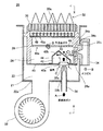
次に、図1の燃料電池発電システムの一部を構成する燃焼装置20を図2と図3を参照して詳細に説明する。図2は本実施例に係る燃焼装置の断面図であり、図3は図2のX−X線断面図である。
図2と図3に示すように、燃焼装置20は、アウターケース22によって外枠が構成されている。このアウターケース22には、孔部22a〜22cが形成されている。孔部22aには、送風ファン38の先端部が挿入された状態で取り付けられている。この送風ファン38を回転させると、アウターケース22によって構成された空気供給室21内に空気が取り入れられる。孔部22bには、原燃料ガスの流路管36の下流側に設けられたノズル36aが挿入されている。この状態で流路管36は固定されている。図3に示すように、孔部22bは2箇所に設けられており、それぞれの孔部に2本の流路管36が接続されている。孔部22cには、オフガスの流路管34の段差部34bが挿入されている。この状態で流路管34は固定されている。この流路管34の上流側は、オフガスを供給する燃料電池62(図1参照)に接続されている。図3に示すように、オフガスのノズル34a(流路管34)は6本設けられている。
【0016】
アウターケース22には、混合ケース26が取り付けられている。この混合ケース26の上流側(送風ファン38と原燃料の流路管36が位置する側)の端部には、導入板40が取り付けられている。この導入板40には、流路管36からの原燃料ガスと送風ファン38からの空気の導入孔40aが形成されている。この導入板40で区切られることによって、混合ケース26内に混合室24が形成されている。この混合室24のオフガスの流路管34側には孔部26aが設けられている。この孔部26aには、流路管34のノズル34aが挿入されている。導入板40の下流側(混合室24側)の面には、囲い板42が取り付けられている。この囲い板42は、原燃料ガスとオフガスと空気を予め混合するための予備混合室44を形成している。この囲い板42には、第1スリット群42aと第2スリット群42bが形成されている。第1スリット群42aは、図2のX−X線断面図である図3に示すように、7つの矩形状のスリットが並列して形成されている。図示を省略するが、第2スリット群42bも第1スリット群42aと同様に、複数の矩形状のスリットが並列して形成されている。
【0017】
この囲い板42より下流側には、混合板46が混合ケース26に連設して形成されている。この混合板46には、細長い矩形状のスリット46aが1つ形成されている。この混合板46より下流側には、分布板48が設けられている。この分布板48は混合ケース26に取り付けられている。この分布板48には、多数の小孔群48aが形成されている。この分布板48より下流側には、バーナ30が設けられている。このバーナ30は混合ケース26に取り付けられている。このバーナ30はセラミックス等によって形成されており、バーナ30側からみた平面図である図4によく示されるように、多数の炎口群30aが形成されている。符号32は、この炎口群30aより炎が出ている状態を示している。
【0018】
次に、本実施例に係る燃焼装置20の作用を図2と図3を参照して説明する。燃焼装置20の燃焼運転が開始されると、図示しない元ガス弁が開弁され、矢印Aに示すように、原燃料ガスが流路管36を通じてノズル36aから予備混合室44内に供給される。同時に、送風ファン38から空気供給室21に強制的に燃焼用一次空気が送り込まれ、この一次空気はさらに矢印Cに示すように導入孔40aを介して予備混合室44内に供給される。そして、しばらくした後、燃料電池62(図1参照)から、オフガスが矢印Bに示すように、流路管34を通じてノズル34aから予備混合室44(一部は混合室24)内に供給される。このようにしばらくした後にオフガスが供給されるのは、図1に示すように、改質ガスが燃料電池62を通ってオフガスとなり予備混合室44(一部は混合室24)内に供給される際に、流路管34の長さの分だけ時間がかかるからである。
すると、これらの原燃料ガス、オフガス、空気が囲い板42に衝突し、予備混合室44内で渦流を形成しながら攪拌され、予備的に混合される。
【0019】
その後、予備混合されたガスは、囲い板42に設けられた第1スリット群42aと第2スリット群42bを通過して、混合板46に衝突する。混合板46に衝突したガスは、混合室24内で十分に混合された後、矢印Dに示すように細長い矩形状のスリット46aを通過する。このスリット46aを通過したガスは、原燃料ガスとオフガスと空気がほぼ均一に混合された予混合ガスとなっている。その後、この予混合ガスは分布板48に形成された多数の小孔群48aを通過することによって、均一な流速分布となる。均一な流速分布となった予混合ガスはバーナ30に供給される。この予混合ガスは、バーナ30の近傍に設けられた点火プラグ(図示せず)により点火されて、全一次燃焼される。
【0020】
本実施例によると、原燃料ガスとオフガスを1つの燃焼装置20で燃焼させるため、原燃料ガスとオフガスを各々別の燃焼装置で燃焼させる場合に比べてコストを低減できる。また、図1に示す燃料電池発電システムでは、燃料電池62の負荷変動に応じて発電出力が変動するので、燃料電池62で消費される改質ガス中の水素量は負荷変動に応じて大きく変動する。このため、燃料電池62から排出されるオフガスの流量(オフガス中の水素量)も大きく変動し得る。しかしながら本実施例によると、図2に示すように原燃料ガスの流路管36とオフガスの流路管34が混合室24に各々独立して接続されているため、オフガスの流量変動によって原燃料ガスの流量変動が生じない。このため、オフガスの流量変動に伴う原燃料ガスとオフガスと一次空気の混合比率の変動を小さく抑えることができる。従って、原燃料ガスとオフガスと一次空気の予混合ガスを適正な空気過剰率で燃焼させることができるため、不完全燃焼や失火の発生を防止できる。
【0021】
また、本実施例によると、図2に示すように原燃料ガスとオフガスを1つの燃焼装置20の混合室24で混合させてバーナ30で燃焼させるため、両ガスの発熱量が大きく異なっていても(原燃料ガス:9000〜32000kcal/m3、オフガス:800〜3000kcal/m3)、燃焼熱量の位置的な分布のばらつきを抑えることができる。また、原燃料ガスの流路管36とオフガスの流路管34が混合室24に各々独立して接続されているため、オフガスの流量変動によって原燃料ガスの流量変動が生じない。上記のようにオフガスの流量は燃料電池62の負荷変動によって大きく変動しやすいが、オフガスの発熱量は小さいため、オフガスの流量変動が生じても本実施例のように原燃料ガスの流量を一定に維持できれば、全体の燃焼熱量の変動は小さく抑えることができる。
従って、本実施例によると、オフガスの流量変動が生じても、改質器56の改質効率の低下や改質触媒の劣化を小さく抑えることができる。
【0022】
本発明の他の実施例としては、図5と図6に示すような燃焼装置であってもよい。図5は他の実施例に係る燃焼装置の断面図であり、図6は図5のX−X線断面図である。
図5と図6に示すように、本発明の他の実施例に係る燃焼装置20bでは、オフガスの流路管34と原燃料ガスの流路管36が並列に設けられている。具体的には、アウターケースの孔部22cに、オフガスの流路管34の段差部34bと、原燃料ガスの流路管36の段差部36bが挿入されている。また、混合ケース26の孔部26aにオフガスのノズル34aが挿入され、孔部26bに原燃料ガスのノズル36aが挿入されている。
また、混合ケース26の導入板40より上流側(送風ファン38側)の端部に仕切り板39が取り付けられている。この仕切り板39には開口39aが形成されている。この仕切り板39と導入板40によって区切られた空間23内には、原燃料ガスのノズル36aが突出している。このため、空間23は、原燃料ガスと空気を予め混合するための予備混合室としての機能を果たしている。
【0023】
以上、本発明の実施例に係る燃焼装置とこれを含む燃料電池発電システムについて説明したが、本発明の適用範囲は上記の実施例になんら限定されるものではない。すなわち、本発明は、当業者の知識に基づいて種々の変更、改良を施した形態で実施することができる。
例えば、本実施例では、原燃料ガスを供給する流路管36(ノズル36a)が2本の場合を説明したが、本発明の適用範囲はこれに限られない。原燃料ガスが囲い板42に衝突しさえすれば、流路管36の本数は6本であってもよい。6本の場合の方が原燃料ガスと他のガスと空気をより混合しやすい。
【図面の簡単な説明】
【図1】本発明の実施例に係る燃焼装置を含む燃料電池発電システムの模式図。
【図2】本発明の実施例に係る燃焼装置の断面図。
【図3】図2のX−X線断面図。
【図4】バーナ側からみた平面図。
【図5】本発明の他の実施例に係る燃焼装置の断面図。
【図6】図5のX−X線断面図。
【図7】従来技術に係る燃焼装置の説明図(1)。
【図8】従来技術に係る燃焼装置の説明図(2)。
【符号の説明】
20:燃焼装置
21:空気供給室
22:アウターケース、22a〜c:孔部
24:混合室
26:混合ケース
30:バーナ、30a:炎口群
32:炎
34:オフガスの流路管、34a:ノズル、34b:段差部
36:原燃料ガスの流路管、36a:ノズル、36b:段差部
38:送風ファン
40:導入板、40a:導入孔
42:囲い板、42a:第1スリット群、42b:第2スリット群
44:予備混合室
46:混合板、46a:スリット
48:分布板、48a:小孔群
50:ポンプ
52:水の流路管
54:改質燃料の流路管
56:改質器
60:改質ガスの流路管
62:燃料電池
64:ガバナ[0001]
BACKGROUND OF THE INVENTION
The present invention relates to a combustion apparatus. More specifically, the present invention relates to an all-primary combustion type combustion apparatus including a mixing chamber in which two kinds of gas and primary air are mixed to form a premixed gas, and a burner that performs all primary combustion of the premixed gas.
[0002]
[Prior art]
2. Description of the Related Art An all-primary combustion type combustion apparatus is known that includes a mixing chamber that mixes raw fuel gas and primary air to form a premixed gas, and a burner that performs primary combustion of the premixed gas. In addition to the raw fuel gas, another gas may be supplied to the mixing chamber of the combustion apparatus. An example of such a combustion apparatus will be described with reference to FIG. FIG. 7 is an explanatory diagram of a combustion apparatus according to the prior art.
FIG. 7 shows an example in which the combustion device 120 is incorporated in a fuel cell power generation system. This fuel cell power generation system mainly includes a
[0003]
In the case of supplying two types of gases (raw fuel gas and off gas in the above case) to the mixing chamber of the combustion apparatus, in the method shown in FIG. 7, the flow path pipe of the raw fuel gas is supplied to the
On the other hand, as shown in FIG. 8, there is also a
[0004]
[Problems to be solved by the invention]
In the method shown in FIG. 7, two
[0005]
On the other hand, in the method shown in FIG. 8, if the flow rate of the off gas is varied, the flow rate of the raw fuel gas is varied. In the method of FIG. 7, the flow rate of the raw fuel gas does not change even if the flow rate of the off gas varies. As described above, the calorific value of the raw fuel gas is about 3 to 40 times the calorific value of the off gas, and when the raw fuel gas is fluctuated according to the fluctuation of the off gas flow rate as in the method of FIG. The calorific value fluctuates greatly. Rather, if the flow rate of the raw fuel gas is kept constant against fluctuations in the flow rate of off gas as in the method of FIG.
[0006]
In the system shown in FIG. 8, the reason why the flow rate of the raw fuel gas is changed when the flow rate of the off gas is changed will be described. Normally, a
[0007]
The above-described flow rate fluctuation problem and combustion heat quantity variation / variation problem are not limited to the combination of raw fuel gas and off-gas, and are common problems when two types of gas are burned. An object of the present invention is to realize a combustion apparatus that does not cause fluctuations in the flow rate of one gas due to fluctuations in the flow rate of one gas, even though the cost is low, when two types of gas are burned.
[0008]
[Means for solving the problem, operation and effect]
In order to solve the above-described problem, a combustion apparatus according to the present invention includes a mixing chamber that mixes off-gas discharged from a fuel cell , raw fuel gas, and primary air fed by a fan into a premixed gas, A burner for burning the premixed gas is provided. The off-gas flow path and the raw fuel gas flow path are independently connected to the mixing chamber, and the off-gas flow path and the primary air flow path are connected to the mixing chamber. Each is connected independently . Examples of the “raw fuel gas” include hydrocarbon fuels such as butane gas, propane gas, methane gas, ethane gas, kerosene and gasoline, and alcohol fuels such as methanol and ethanol. Here, as long as the “ off gas channel and the raw fuel gas channel” are independently connected to the mixing chamber, a plurality of each gas channel may be connected.
According to the combustion apparatus according to the present invention, the off-gas and raw fuel gas discharged from the fuel cell are burned by one combustion apparatus, and therefore the cost is lower than when the off-gas and raw fuel gas are burned by separate combustion apparatuses. Can be reduced. Without leaving in it, the flow path of the off-gas and the raw fuel gas are each independently connected to the mixing chamber, since the flow path of the off-gas and primary air are each independently connected to the mixing chamber, the raw by the flow rate fluctuation of the off-gas No fluctuations in the flow rate of fuel gas or primary air . For this reason, the fluctuation | variation of the mixing ratio of off gas , raw fuel gas, and primary air accompanying the flow volume fluctuation | variation of off gas can be suppressed small. Accordingly, the premixed gas of off-gas , raw fuel gas, and primary air can be burned at an appropriate excess air ratio, so that incomplete combustion and misfire can be prevented. Even if there is a fluctuation in the flow rate of the off-gas discharged from the fuel cell, the fluctuation in the flow rate of the raw fuel gas does not occur.
[0011]
DETAILED DESCRIPTION OF THE INVENTION
The main features of the embodiment of the present invention will be described.
A reformer that heats the reformed fuel to generate a hydrogen-rich reformed gas, a fuel cell that generates electricity using the reformed gas generated by the reformer as fuel, and an off-gas discharged from the fuel cell. A fuel cell power generation system including a combustion device that burns with raw fuel gas and uses the combustion heat for a reforming reaction of a reformer,
The combustion apparatus includes a mixing chamber that mixes raw fuel gas, off-gas, and primary air to make a premixed gas, and a burner that burns the premixed gas, and the mixing chamber has a flow tube for the raw fuel gas. And a fuel cell power generation system, wherein the off-gas channel pipes are independently connected to each other.
[0012]
【Example】
A preferred embodiment of the present invention will be described with reference to the drawings. First, a fuel cell power generation system including an all primary combustion type combustion apparatus according to this embodiment will be described with reference to FIG. FIG. 1 is a schematic diagram of a fuel cell power generation system including a combustion apparatus according to the present embodiment.
The fuel cell power generation system shown in FIG. 1 mainly includes a
[0013]
In this fuel cell power generation system, the
[0014]
In order for the
[0015]
Next, the
As shown in FIG. 2 and FIG. 3, the outer frame of the
[0016]
A mixing
[0017]
On the downstream side of the surrounding
[0018]
Next, the operation of the
Then, these raw fuel gas, off gas, and air collide with the surrounding
[0019]
Thereafter, the premixed gas passes through the
[0020]
According to the present embodiment, since the raw fuel gas and the off gas are burned by one
[0021]
Further, according to the present embodiment, as shown in FIG. 2, since the raw fuel gas and the off gas are mixed in the mixing
Therefore, according to this embodiment, it is possible to suppress a reduction in reforming efficiency of the
[0022]
Another embodiment of the present invention may be a combustion apparatus as shown in FIGS. FIG. 5 is a sectional view of a combustion apparatus according to another embodiment, and FIG. 6 is a sectional view taken along line XX of FIG.
As shown in FIGS. 5 and 6, in the
Further, a
[0023]
The combustion apparatus according to the embodiment of the present invention and the fuel cell power generation system including the combustion apparatus have been described above, but the scope of the present invention is not limited to the above-described embodiment. In other words, the present invention can be implemented in various modifications and improvements based on the knowledge of those skilled in the art.
For example, in this embodiment, the case where there are two flow path pipes 36 (
[Brief description of the drawings]
FIG. 1 is a schematic diagram of a fuel cell power generation system including a combustion apparatus according to an embodiment of the present invention.
FIG. 2 is a cross-sectional view of a combustion apparatus according to an embodiment of the present invention.
3 is a cross-sectional view taken along line XX in FIG.
FIG. 4 is a plan view seen from the burner side.
FIG. 5 is a sectional view of a combustion apparatus according to another embodiment of the present invention.
6 is a cross-sectional view taken along line XX in FIG.
FIG. 7 is an explanatory diagram (1) of a combustion apparatus according to the prior art.
FIG. 8 is an explanatory diagram (2) of a combustion apparatus according to the prior art.
[Explanation of symbols]
20: Combustion device 21: Air supply chamber 22: Outer case, 22a to c: Hole 24: Mixing chamber 26: Mixing case 30: Burner, 30a: Flame group 32: Flame 34: Off-gas flow pipe, 34a:
Claims (1)
前記オフガスの流路と、前記原燃料ガスの流路が、前記混合室に各々独立して接続されており、
前記オフガスの流路と、前記一次空気の流路が、前記混合室に各々独立して接続されていることを特徴とする燃焼装置。A combustion apparatus comprising a mixing chamber that mixes off-gas discharged from a fuel cell , raw fuel gas, and primary air sent by a fan into a premixed gas, and a burner that burns the premixed gas,
The off gas flow path and the raw fuel gas flow path are independently connected to the mixing chamber ,
The combustion apparatus, wherein the off-gas flow path and the primary air flow path are independently connected to the mixing chamber .
Priority Applications (1)
| Application Number | Priority Date | Filing Date | Title |
|---|---|---|---|
| JP2001013030A JP3895112B2 (en) | 2001-01-22 | 2001-01-22 | Combustion device |
Applications Claiming Priority (1)
| Application Number | Priority Date | Filing Date | Title |
|---|---|---|---|
| JP2001013030A JP3895112B2 (en) | 2001-01-22 | 2001-01-22 | Combustion device |
Publications (2)
| Publication Number | Publication Date |
|---|---|
| JP2002213710A JP2002213710A (en) | 2002-07-31 |
| JP3895112B2 true JP3895112B2 (en) | 2007-03-22 |
Family
ID=18879953
Family Applications (1)
| Application Number | Title | Priority Date | Filing Date |
|---|---|---|---|
| JP2001013030A Expired - Fee Related JP3895112B2 (en) | 2001-01-22 | 2001-01-22 | Combustion device |
Country Status (1)
| Country | Link |
|---|---|
| JP (1) | JP3895112B2 (en) |
Families Citing this family (8)
| Publication number | Priority date | Publication date | Assignee | Title |
|---|---|---|---|---|
| JP4340873B2 (en) * | 2004-01-06 | 2009-10-07 | 株式会社ノーリツ | Combustion device |
| JP2006100206A (en) * | 2004-09-30 | 2006-04-13 | Dainichi Co Ltd | Combustion device for hydrogen supply device used in fuel cell |
| JP4945901B2 (en) * | 2005-01-07 | 2012-06-06 | 株式会社日立製作所 | Operation method of fuel cell power generation system |
| JP5202069B2 (en) * | 2008-03-28 | 2013-06-05 | アイシン精機株式会社 | Combustion device of reformer and reformer |
| JP4983859B2 (en) * | 2009-05-29 | 2012-07-25 | カシオ計算機株式会社 | Combustor |
| CN102734792A (en) * | 2011-04-12 | 2012-10-17 | 无锡市晨光耐火材料有限公司 | Flue gas mixing chamber |
| JP6422323B2 (en) * | 2014-12-11 | 2018-11-14 | 東京瓦斯株式会社 | Fuel cell module |
| CN117080504B (en) * | 2023-10-13 | 2024-01-26 | 成都岷山绿氢能源有限公司 | Fuel cell system and control method |
-
2001
- 2001-01-22 JP JP2001013030A patent/JP3895112B2/en not_active Expired - Fee Related
Also Published As
| Publication number | Publication date |
|---|---|
| JP2002213710A (en) | 2002-07-31 |
Similar Documents
| Publication | Publication Date | Title |
|---|---|---|
| JP3196549B2 (en) | Power generation system with fuel reformer | |
| JP4718188B2 (en) | Non-catalytic combustor for reducing NOx emissions | |
| US20110079016A1 (en) | Compact aircraft combustor | |
| JPH0861674A (en) | Catalytic method | |
| JP2006118854A (en) | Method and system for rich-lean catalytic combustion | |
| JP2002213710A (en) | Combustion device | |
| CN101292386B (en) | Fuel cell system and method for operating a reformer | |
| CN114738751B (en) | Anti-flashback multi-nozzle burner and waste gas treatment method | |
| JP3765989B2 (en) | Reformer heating method and heating apparatus | |
| EP1085261A1 (en) | Improved nozzle-mix burner | |
| JP2003074804A (en) | Combustion equipment | |
| JP2007255744A (en) | Tubular flame burner and fuel reforming device | |
| JP2008533656A (en) | Reformer, fuel cell system, and method of operating fuel cell system | |
| US20070183949A1 (en) | Hydrocarbon reformer system including a pleated static mixer | |
| JP2004134253A (en) | Heater for apparatus for producing hydrogen in fuel cell system | |
| JP5525855B2 (en) | Combustion device | |
| JP2003007325A (en) | Fuel cell anode off-gas combustor, hydrogen production device, and fuel cell power generation system | |
| JP4108630B2 (en) | Combustion equipment for different types of fuel | |
| KR20220115119A (en) | Fuel reformer burner of fuel cell system | |
| JP2000329346A (en) | Premixed combustor and cogeneration system having the combustor | |
| Chun et al. | Development of a Combined Plasma‐Matrix Reformer for Solid Oxide Fuel Cell Application | |
| RU2080518C1 (en) | Flame tube burner device | |
| JP4703250B2 (en) | Combustion device for hydrogen supply device for fuel cell | |
| JP2003282113A (en) | Solid oxide fuel cell system | |
| JP2002025597A (en) | Reforming device for fuel cell and its operating method |
Legal Events
| Date | Code | Title | Description |
|---|---|---|---|
| A131 | Notification of reasons for refusal |
Free format text: JAPANESE INTERMEDIATE CODE: A131 Effective date: 20051018 |
|
| A521 | Written amendment |
Free format text: JAPANESE INTERMEDIATE CODE: A523 Effective date: 20051213 |
|
| RD02 | Notification of acceptance of power of attorney |
Free format text: JAPANESE INTERMEDIATE CODE: A7422 Effective date: 20051213 |
|
| A131 | Notification of reasons for refusal |
Free format text: JAPANESE INTERMEDIATE CODE: A131 Effective date: 20060404 |
|
| AA91 | Notification of revocation by ex officio |
Free format text: JAPANESE INTERMEDIATE CODE: A971091 Effective date: 20060418 |
|
| A131 | Notification of reasons for refusal |
Free format text: JAPANESE INTERMEDIATE CODE: A131 Effective date: 20060516 |
|
| A521 | Written amendment |
Free format text: JAPANESE INTERMEDIATE CODE: A523 Effective date: 20060712 |
|
| TRDD | Decision of grant or rejection written | ||
| A01 | Written decision to grant a patent or to grant a registration (utility model) |
Free format text: JAPANESE INTERMEDIATE CODE: A01 Effective date: 20061212 |
|
| A61 | First payment of annual fees (during grant procedure) |
Free format text: JAPANESE INTERMEDIATE CODE: A61 Effective date: 20061213 |
|
| R150 | Certificate of patent or registration of utility model |
Free format text: JAPANESE INTERMEDIATE CODE: R150 |
|
| FPAY | Renewal fee payment (event date is renewal date of database) |
Free format text: PAYMENT UNTIL: 20101222 Year of fee payment: 4 |
|
| FPAY | Renewal fee payment (event date is renewal date of database) |
Free format text: PAYMENT UNTIL: 20101222 Year of fee payment: 4 |
|
| FPAY | Renewal fee payment (event date is renewal date of database) |
Free format text: PAYMENT UNTIL: 20111222 Year of fee payment: 5 |
|
| FPAY | Renewal fee payment (event date is renewal date of database) |
Free format text: PAYMENT UNTIL: 20111222 Year of fee payment: 5 |
|
| FPAY | Renewal fee payment (event date is renewal date of database) |
Free format text: PAYMENT UNTIL: 20121222 Year of fee payment: 6 |
|
| FPAY | Renewal fee payment (event date is renewal date of database) |
Free format text: PAYMENT UNTIL: 20121222 Year of fee payment: 6 |
|
| FPAY | Renewal fee payment (event date is renewal date of database) |
Free format text: PAYMENT UNTIL: 20131222 Year of fee payment: 7 |
|
| R250 | Receipt of annual fees |
Free format text: JAPANESE INTERMEDIATE CODE: R250 |
|
| R250 | Receipt of annual fees |
Free format text: JAPANESE INTERMEDIATE CODE: R250 |
|
| R250 | Receipt of annual fees |
Free format text: JAPANESE INTERMEDIATE CODE: R250 |
|
| LAPS | Cancellation because of no payment of annual fees |