JP3933246B2 - Inkwell cover film - Google Patents
Inkwell cover film Download PDFInfo
- Publication number
- JP3933246B2 JP3933246B2 JP10385297A JP10385297A JP3933246B2 JP 3933246 B2 JP3933246 B2 JP 3933246B2 JP 10385297 A JP10385297 A JP 10385297A JP 10385297 A JP10385297 A JP 10385297A JP 3933246 B2 JP3933246 B2 JP 3933246B2
- Authority
- JP
- Japan
- Prior art keywords
- ink fountain
- cover film
- ink
- side plate
- fountain
- Prior art date
- Legal status (The legal status is an assumption and is not a legal conclusion. Google has not performed a legal analysis and makes no representation as to the accuracy of the status listed.)
- Expired - Fee Related
Links
Images




Landscapes
- Inking, Control Or Cleaning Of Printing Machines (AREA)
Description
【0001】
【発明の属する技術分野】
本発明は、オフセット印刷機、凸版印刷機等に用いるインキ壺の内面を保護するためのインキ壺カバーフィルムに関する。
【0002】
【従来の技術】
オフセット印刷機又は凸版印刷機におけるインキ供給には、通常インキ壺方式が使用されており、インキ壺のインキが元ローラ(壺ローラともいう)から呼び出しローラを介してインキ練りローラに供給され、多数のインキ練りローラで練られた後版胴に供給されている。かかるインキ装置において、印刷品目を替える場合、使用済のインキを洗浄しなければならない。洗浄が不十分な状態で新しいインキを投入すると古いインキと混じってしまって正確な色再現できないため、特に暗色から明色に替える時は入念に洗浄を行う。
【0003】
インキ洗浄はローラ洗浄とインキ壺洗浄とに大きく分けられる。一般的にローラ洗浄は印刷機を運転状態にしてローラ群に洗浄液をかけ、ドクタでインキの混ざった洗浄液を回収する。ローラ洗浄は自動化が進んでおり、多くの印刷機においてこれらの作業を自動で行うことができる。一方、インキ壺の洗浄はインキ壺の形状が複雑なことから自動化が難しく、ほぼ全ての印刷機において手作業で行われている。
【0004】
インキ壺の洗浄を自動化する方法はいくつか提案されているが、構造が比較的簡単で現実性のある方法としては、インキ壺及びインキキーをカバーフィルムで覆い、洗浄時にカバーフィルムを交換することで洗浄を自動化もしくは簡単化する方法で提案されている。
【0005】
【発明が解決しようとする課題】
しかしながら、従来提案されているカバーフィルムは、インキ壺の底面のみを覆うものであるので、インキ壺側面の保護ができず、このため従来はインキ壺側面を、手作業によって洗浄するか、或いはインキ壺側面専用の小さなカバーフィルムを貼り付けておいて、それを手作業で剥がすという作業を行っている。このため、カバーフィルムを用いても洗浄作業の効率化にはつながりにくく、メリットが小さいという問題があった。
【0006】
本発明は、かかる問題点に鑑みて為されたもので、オフセット印刷機、凸版印刷機等の印刷機のインキ壺の内側の底面及び側面を覆うことができるインキ壺カバーフィルムであって、品目替え時等においては、そのインキ壺カバーフィルムのインキで汚れた部分を容易に交換することができ、それによって容易にインキ壺のインキを除去してインキ壺をきれいにすることの可能なインキ壺カバーフィルムを提供することを目的とする。
【0007】
【課題を解決するための手段】
本発明は上記目的を達成するため、インキ壺の内面を保護するために使用するインキ壺カバーフィルムとして、前記インキ壺内面のうち、インキ壺底面を覆う幅を有する長尺の直線部と、その直線部の長手方向に一定ピッチで且つその直線部の両側に形成された複数のフラップ部を備えたものを用い、その各フラップ部を、前記インキ壺側面を覆う側面保護部と、元ローラとインキ壺側板との間にはさみ込まれる余裕部とを有する形状とすると共にその余裕部を前記直線部から分離可能としたものである。
【0008】
上記構成のインキ壺カバーフィルムを、直線部がインキ壺底面下端のインキキーを経てインキ壺底面を覆うように通し、両側のフラップ部の側面保護部でインキ壺側面(インキ壺側板の内面)を覆うと共に余裕部を元ローラとインキ壺側板の端面との間にはさみ込まれるように取り付けることで、インキ壺内面全域のみならず、インキ壺側板の、元ローラに押し付けられる端面をも良好に覆ってインキで汚れないように保護することができ、色替えのための洗浄時には、そのインキ壺カバーフィルムを、直線部の長手方向に移動させ、インキの付着した部分をインキ壺外に送り出し、新たな部分をインキ壺内に位置させることで、インキ壺内面のインキ汚れを無くすことができ、従来行っていた手作業によるインキ壺洗浄動作を不要とできる。また、インキ壺カバーフィルムの新たな部分をインキ壺内に移動させ、且つフラップ部をインキ壺側板に取り付ける作業は比較的簡単であるので、容易に自動化することができ、また、手作業で行うとしても作業が容易で、作業者への作業負担を小さくできる。
【0009】
【発明の実施の形態】
以下、図面に示す本発明の好適な実施例を説明する。図1は、オフセット印刷機或いは凸版印刷機に設けられ、本発明の一実施例によるインキ壺カバーフィルム(以下カバーフィルムと略称する)を使用するインキ壺装置を備えたインキ装置の要部を示す概略断面図、図2はそのインキ装置に設けられたインキ壺装置の概略側面図、図3はそのインキ壺装置の概略平面図、図4はそのインキ壺装置に用いたカバーフィルムの一部の概略平面図、図5(a)、(b)、(c)はそれぞれ、そのインキ壺装置を異なる作動状態で示す概略斜視図、図6(a)、(b)、(c)、(d)はそれぞれ、そのインキ壺装置を異なる作動状態で示す概略断面図又は側面図である。図1〜図6において、1は印刷ユニットのフレーム、2はインキ壺装置(詳細は後述)、3はそのインキ壺装置2の一部を構成する元ローラ、4は呼び出しローラ、5はインキ練りローラであり、これらは版胴(図示せず)に対してインキ供給を行うインキ装置を構成している。
【0010】
インキ壺装置2は、元ローラ3と、その元ローラ3に近接配置され、平坦なインキ壺底面7aを形成するインキ壺本体7と、そのインキ壺本体7に、インキ壺底面7aの下端に位置するように設けられ、元ローラ3との間隙を調整可能な複数のインキキー8と、そのインキキー8の位置を調整するためのインキキー調整用ロッド9と、インキ壺本体7の両端に設けられ、インキ壺側面10aを形成するインキ壺側板10等を備えている。このインキ壺側板10は、元ローラ3の外周面に押し付けられてインキ漏れを防止するための円弧状の端面10bを備えている。更に、このインキ壺側板10は、インキ壺本体7の両端外面7bに接するように、且つ支軸11を中心として旋回可能に取り付けられており、インキ壺の両端に位置する作動位置〔図5(a)、図6(a)に示す位置〕と、その位置よりも低い、好ましくはインキ壺底面7aよりも低い退避位置〔図5(b)、図6(b)に示す位置〕とに移動可能となっている。そして、このインキ壺側板10には、そのインキ壺側板10を作動位置及び退避位置に往復動させるためのエアシリンダ等のインキ壺側板駆動装置(図示せず)が連結されている。
【0011】
インキ壺本体7は、図6(a)に示すように、元ローラ3と共にインキ壺を形成する作動位置と、図6(b)に示すように、作動位置よりも下方に退避し且つインキ壺底面7aがほぼ水平となる退避位置に移動可能に設けられている。また、そのインキ壺本体7には、インキ壺本体7を作動位置と退避位置とに往復動させるエアシリンダ等の駆動装置(図示せず)が連結されている。
【0012】
図1〜図6において、インキ壺装置2は更に、インキ壺内面を保護するための長尺のカバーフィルム15と、そのカバーフィルム15を繰り出すカバーフィルム供給ロール16と、カバーフィルム供給ロール16から引き出され、インキキー8を経てインキ壺底面7aを覆うように通されたカバーフィルム15の、インキ壺底面7aを覆っていた部分を引き出し、新たな部分をインキ壺底面7a上に位置させるよう、カバーフィルム15を移動させるカバーフィルム搬送装置17を備えている。ここでは、カバーフィルム搬送装置17として、カバーフィルム15を案内するガイドローラ18とカバーフィルム15を巻き上げる巻取ロール19を設けており、その巻取ロール19には駆動モータ(図示せず)が連結されている。更に、その巻取ロール19の上流に、カバーフィルム15上の残インキ20〔図6(b)参照〕をかき取り除去する残インキ除去装置21が設けられている。
【0013】
ここで使用するカバーフィルム15は、図4に示すように、長尺の且つ一定幅の直線部15aと、その直線部の長手方向に一定ピッチで且つその直線部15aの両側に形成された複数のフラップ部15bを備えたものである。直線部15aの幅は、一対のインキ壺側面10a、10a間のインキ壺底面7aの幅に等しく定められている。フラップ部15bは、インキ壺側面10a(インキ壺側板10の内面)を覆うほぼ三角形の側面保護部15b1 と、それに続いて設けられた余裕部15b2 とからなり、その余裕部15b2 は元ローラ3とそれに対向するインキ壺側板10の端面10bとの間にはさみ込まれるためのものである。従って、側面保護部15b1 は、インキ壺側面10aと同等若しくはそれよりも大きい面積を有し、また、余裕部15b2 はインキ壺側板10の端面10bと同等若しくはそれよりも大きい面積を有している。ここで、フラップ部15bの側面保護部15b1 は、その全長に渡って直線部15aにつながっているが、余裕部15b2 は直線部15aとの間に細い切り込み15cを介在させ、これによって直線部15aから分離可能となっている。このように余裕部15b2 を直線部15aから切り離しているので、カバーフィルム15の装着時にしわの発生を抑えながら、余裕部15b2 をインキ壺側板10の元ローラに接触する円弧状の端面10bを覆うように折り曲げることができる。切り込み15cの奥の部分15dには丸みを付けており、これによって切り込み15cが起点となってカバーフィルム15が裂けることを防止している。カバーフィルム15はロール状に巻き取られた状態で供給され、カバーフィルム供給ロール16としてセットされる。
【0014】
カバーフィルム15の材料としては、PET(ポリエチレンテレフタレート)、ナイロン、ポリカーボネート等の軟質樹脂フィルムを用いることができ、その厚さとしては、耐久性、柔軟性等を考慮して、100〜200μm程度とすることが好ましい。また、フィルム表面にハードコート処理を施せばフィルムの耐久性を大きく向上させることができる。
【0015】
図1、図3において、カバーフィルム供給ロール16から引き出されたカバーフィルム15の搬送途中には、巻き上げ長さ測定ローラ23が配置され、ロータリーエンコーダ24に接続されている。このロータリーエンコーダ24は、巻取ロール19によってカバーフィルム15を巻き上げ、カバーフィルム15の新たな部分をインキ壺底面7a上に送り込む際にカバーフィルム15の送り量を測定し、カバーフィルム15の所望の位置(フラップ部15bを設けた位置)を正しくインキ壺底面7a上に位置決めすることができるように、設けている。なお、カバーフィルム15を巻き上げた際の位置決めは、巻き上げ長さ測定ローラ23及びロータリーエンコーダ24を設ける場合に限らず、適宜変更可能であり、例えば、図7に示すように、カバーフィルム15にセンサ検知用小穴26或いはマークを、一定ピッチで設けておき、図8に示すように、カバーフィルム15の搬送経路に配置した光電センサ27でそのセンサ検知用小穴26或いはマークを検知する方法を採用してもよい。
【0016】
図3において、元ローラ3の両端には、元ローラ3の外径とほぼ等しい外径を有する円筒部材30が、元ローラ3が回転しても回転しないように配置されている。インキ壺側板10の元ローラ3に接する部分は肉厚に形成され、元ローラ3と円筒部材30の両方に押し付けられるようになっている。
【0017】
なお、図示は省略しているが、以下に説明する洗浄動作を自動的に行うためのシーケンス制御装置が設けられている。
【0018】
次に、上記構成のインキ壺装置2について、その動作を説明する。
通常の印刷時には、インキ壺本体7及びインキ壺側板10は図1、図5(a)、図6(a)等に示す作動位置を占めており、カバーフィルム15はインキ壺内面を覆っている。すなわち、カバーフィルム15の直線部15a(図4参照)はインキキー8及びインキ壺底面7aを覆っており、フラップ部15bの側面保護部15b1 がインキ壺側面10aを覆っており、更に余裕部15b2 がインキ壺側板10と元ローラ3及び円筒部材30の間に挟み付けられている。この状態で印刷が行われる。すなわち、図1において、元ローラ3がゆっくり矢印方向に回転し、インキ壺内に供給されているインキが元ローラ3の外周面にインキ膜を形成し、そのインキが、元ローラ3に接触する位置に移動した呼び出しローラ4に転移され、次いで、呼び出しローラ4がインキ練りローラ5に接触する位置に移動してインキをインキ練りローラ5に転移させるという動作でインキ供給が行われる。
【0019】
この動作中、インキ壺内面は、底面のみならず側面もカバーフィルム15で覆われているので、インキ壺本体7やインキ壺側板10がインキで汚れることはない。また、元ローラ3が回転するので、その元ローラ3とインキ壺側板10とではさみ付けられているカバーフィルム15の余裕部15b2 が元ローラ3で引っ張られる恐れがあるが、この余裕部15b2 は、回転しない円筒部材30とインキ壺側板10とで挟み付けられ固定されているので、そのカバーフィルム15が動いてトラブルを起こすということがない。なお、カバーフィルム15の滑り性が良く、円筒部材30とインキ壺側板10とで余裕部15b2 を固定していなくても、元ローラ3に接触する余裕部15b2 が元ローラ3で引っ張られる恐れがない場合には、円筒部材30は省略してもよい。
【0020】
印刷終了後、インキ壺の洗浄を行う場合は、シーケンス制御装置の洗浄ボタンを押す。すると、図5(b)、図6(b)に示すように、インキ壺本体7が退避位置に下がると共にインキ壺側板10も退避位置に下がり、カバーフィルム15の巻き上げが可能な状態となる。なお、カバーフィルム15の巻き上げは、インキ壺側板10のみを下げた状態としても可能であるが、インキ壺本体7も下げておくとカバーフィルム15の巻き上げ力が小さくて済み、且つ、インキ壺底面7aが水平となって残インキ20の排出が容易となるので、好ましい。
【0021】
次に、巻取ロール19が回転してカバーフィルム15を所定量巻き上げ、残インキ20で汚れた部分を巻き取ると共に、カバーフィルム15の新たな所定の部分をインキ壺本体7上に移動させる。この際、カバーフィルム15上の残インキ20は残インキ除去装置21がかき取って除去しており、このため巻取ロール19内に多量のインキが巻き込まれてトラブルを起こすということが防止される。また、カバーフィルム15の両側縁にはフラップ部15bが水平に延び出しているが、カバーフィルム15の巻き上げの際、インキ壺側板10は下方に退避しているので、そのインキ壺側板10がフラップ部15bの走行に干渉することはない。
【0022】
カバーフィルム15が移動した後、図6(c)に示すようにインキ壺本体7が元の作動位置に戻る。この時の状態が図5(b)に示す状態であり、カバーフィルム15のフラップ部15bがインキ壺底面7aの両側に水平に延び出した状態となっている。次に、インキ壺側板10が上方に旋回し、フラップ部15bを上向きに折り込みつつ移動し、その端面10bと元ローラ3及び円筒部材30との間にフラップ部15bの余裕部15b2 をはさみ込み固定する。これにより、インキ壺内面(インキ壺底面7a及びインキ壺側面10a)にカバーフィルム15が貼り付けられた状態となり、洗浄動作が終了する。なお、インキ壺側板10を上げる動作は、インキ壺本体7を上げる動作と同時に或いはその前に行ってもよいが、インキキー部分のカバーフィルム15にしわが入るのを避けるため、インキ壺本体7を先に上げるのが望ましい。
【0023】
以上のようにしてインキ壺洗浄動作が自動的に行われ、作業者に対する作業負担が大幅に削減される。またこのインキ壺洗浄動作は、印刷機に設けている複数の印刷ユニットについて同時に行われる。かくして、印刷機の各インキ壺の洗浄を極めて短時間に容易に行うことができ、印刷機の停止時間を短縮して生産性を向上させることができる。なお、このインキ壺洗浄動作と並行して、インキ装置の他のローラの洗浄動作も行われる。洗浄動作の終了後、インキ壺にインキを供給し、印刷動作に入る。
【0024】
なお、上記構成のインキ壺装置では、インキ壺側板10を支軸11を中心として旋回可能に設け、インキ壺の両端に位置する作動位置とそれよりも低い退避位置とに移動させる構成としているが、インキ壺側板10の移動は必ずしも旋回方式に限らず、スライド方式としてもよい。すなわち、図9に示すように、インキ壺側板10をインキ壺本体7の両端外面7bに接して斜め下方に直線状に移動するように配置し、図9(a)に示す作動位置から、図9(b)に示すように、インキ壺側板10がインキ壺底面7aよりも低い位置となった退避位置に移動し、また、その位置から図9(c)に示す作動位置に移動するように、エアシリンダ等のインキ壺側板駆動装置(図示せず)を連結しておく。その他の構成は、図1〜図8に示す装置と同様である。図9に示す構成においても、インキ壺側板10を図9(b)に示す退避位置に移動させた状態で、カバーフィルム15を巻き上げて、インキで汚れた部分を排出し、新たな部分をインキ壺底面7a上に位置させ、次いで、インキ壺側板10を図9(c)に示す位置に押し上げることで、カバーフィルム15のフラップ部15bをインキ壺側板10の内面即ちインキ壺端面10a上に位置させることができ、インキ壺の底面のみならず側面にカバーフィルム15をかぶせることができ、従来行っていた手作業によるインキ壺洗浄動作を省略できる。
【0025】
ところで、図4に示すカバーフィルム15は前記したようにロール状に巻き取られ、カバーフィルム供給ロール16として使用されている。そして、このカバーフィルム供給ロール16からのカバーフィルム15は、図5(b)に示すように、巻取ロール19で巻き上げた時にフラップ部15bの余裕部15b2 が後側となって移動するように(図4では矢印A方向に移動するように)配置されている。従って、カバーフィルム15をロール状に巻き取って供給ロール16を製造する場合には、カバーフィルム15を図4で矢印B方向に巻き取る必要がある。この場合、フラップ部15の余裕部15b2 を前にして巻き取る必要があり、その余裕部15b2 が図4に示すように自由に動きうる状態となっていると、余裕部15b2 がめくれて、良好な巻き取りが困難となるという問題の生じることがある。
【0026】
図10はこの問題を解決した実施例のカバーフィルム15Aを示すものである。この実施例のカバーフィルム15Aは、余裕部15b2 の先端と直線部15aとを細い連結部15eで連結しており、それ以外は図4のカバーフィルム15と同様である。ここで、連結部15eは、カバーフィルム15Aを余裕部15b2 を前にして、すなわち矢印B方向に巻き取る際には、余裕部15b2 の先端を直線部15aに連結した状態に保持して、余裕部15b2 のめくれを防止するが、図5(c)に示すようにインキ壺側板10を起こしてフラップ部15bをインキ壺の所定位置にセットする際には、インキ壺側板10で連結部15eを容易に破断しうる程度の強度のものであり、具体的には1〜3mm程度の幅のもの、好ましくは1.5mm程度の幅のものである。この実施例のカバーフィルム15Aは、図4に示すカバーフィルム15と同様にインキ壺装置に使用可能であり、更に、製造時の巻き取りの際に余裕部15b2 のめくれが生じないので、巻き取り作業が容易となるという利点を有している。
【0027】
図11は本発明の更に他の実施例によるカバーフィルム15Bを示すものである。この実施例のカバーフィルム15Bは、直線部15aの両側に、横方向に延びる切れ目15fで区分された長方形状のフラップ部15b′を備えたものであり、そのフラップ部15b′も、インキ壺側面を保護する側面保護部15b1 ′と、元ローラとインキ壺側板との間にはさみ込まれる余裕部15b2 ′とを有している。この実施例のカバーフィルム15Bも、図4に示すカバーフィルム15と同様にインキ壺装置に使用可能である。ただし、インキ壺装置に取り付けた時には、側面保護部15b1 ′がインキ壺側板10よりも大きいため、インキ壺よりも上方に延び出した形状となるが、特に支障はない。また、邪魔になるようなら、インキ壺側板10の上端で折り返しておけばよい。図11に示すカバーフィルム15Bは、カバーフィルムの製造時に打ち抜く部分が少ないため、製造工程が簡略となる利点が得られる。
【0028】
以上に本発明の実施例によるカバーフィルム15、15A、15Bを、自動的にインキ壺洗浄動作(カバーフィルムの移動及びインキ壺内面への装着動作)を行うことの可能なインキ壺装置に用いる場合を説明したが、このカバーフィルム15、15A、15Bは、必ずしもこのような自動洗浄の可能なインキ壺装置に使用する場合に限らず、既存のインキ壺装置に使用することも可能である。その場合には、手動で、カバーフィルムのインキで汚れた部分を長手方向に移動させて新たな部分をインキ壺内に位置させ、且つフラップ部をインキ壺側面にセットすればよい。
【0029】
【発明の効果】
以上に説明したように本発明は、インキ壺の内面を保護するために使用するインキ壺カバーフィルムが、前記インキ壺内面のうち、インキ壺底面を覆う幅を有する長尺の直線部と、その直線部の長手方向に一定ピッチで且つその直線部の両側に連設された複数のフラップ部を備え、その各フラップ部が、前記インキ壺側面を覆う側面保護部と、元ローラとインキ壺側板との間にはさみ込まれる余裕部とを有すると共にその余裕部が前記直線部から分離可能であるという構成としたことにより、そのインキ壺カバーフィルムでインキ壺内面全域のみならず、インキ壺側板の、元ローラに押し付けられる端面をも良好に覆ってインキで汚れないように保護することができ、色替えのための洗浄時には、インキ壺カバーフィルムを、直線部の長手方向に移動させ、インキの付着した部分をインキ壺外に送り出し、新たな部分をインキ壺内に位置させることで、インキ壺内面のインキ汚れを無くすことができ、これらの動作を手作業で行ったとしてもきわめて容易に且つ短時間で行うことができ、インキ壺洗浄を容易に且つ短時間で行うことができるという効果を有している。また、インキ壺カバーフィルムの新たな部分をインキ壺内に移動させ、且つフラップ部をインキ壺側板に取り付ける作業は比較的簡単であるので、容易に自動化することができ、インキ壺洗浄作業の自動化を行うことにより、手作業によるインキ壺洗浄動作を一層削減できると共に、印刷機の停止時間を短縮でき、生産性を向上できるという効果を有している。
【0030】
ここで、前記フラップ部の余裕部の先端を前記直線部に連結しておくと、インキ壺カバーフィルムを製造し、余裕部を前にして巻き取る際に、余裕部がめくれて巻き取り不良を生じるということがなく、製造が容易となるという効果が得られる。
【図面の簡単な説明】
【図1】本発明の実施例によるインキ壺カバーフィルムを使用するインキ壺装置を備えたインキ装置の要部を示す概略断面図
【図2】そのインキ壺装置の概略側面図
【図3】そのインキ壺装置の概略平面図
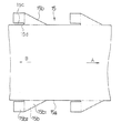
【図4】本発明の一実施例によるカバーフィルムの一部の概略平面図
【図5】(a)、(b)、(c)はそれぞれ、そのインキ壺装置を異なる作動状態で示す概略斜視図
【図6】(a)、(b)、(c)、(d)はそれぞれ、そのインキ壺装置を異なる作動状態で示す概略断面図又は側面図
【図7】本発明の他の実施例によるカバーフィルムの一部を示す概略平面図
【図8】図7に示すカバーフィルムを使用したインキ壺装置の概略断面図
【図9】インキ壺装置の変形例を示すもので、(a)、(b)、(c)はそれぞれ異なる作動状態で示す概略斜視図
【図10】本発明の更に他の実施例によるカバーフィルムの一部を示す概略平面図
【図11】本発明の更に他の実施例によるカバーフィルムの一部を示す概略平面図
【符号の説明】
1 印刷ユニットのフレーム
2 インキ壺装置
3 元ローラ
4 呼び出しローラ
5 インキ練りローラ
7 インキ壺本体
7a インキ壺底面
8 インキキー
10 インキ壺側板
10a インキ壺側面
11 支軸
15、15A、15B カバーフィルム
15a 直線部
15b、15b′ フラップ部
15b1 、15b1 ′ 側面保護部
15b2 、15b2 ′ 余裕部
16 カバーフィルム供給ロール
17、17A カバーフィルム搬送装置
19 巻取ロール
20 残インキ
21 残インキ除去装置
23 巻き上げ長さ測定ローラ
24 ロータリーエンコーダ[0001]
BACKGROUND OF THE INVENTION
The present invention relates to an ink fountain cover film for protecting the inner surface of an ink fountain used in an offset printing press, a relief printing press, and the like.
[0002]
[Prior art]
An ink fountain system is usually used for ink supply in an offset printing press or letterpress printing machine. Ink fountain ink is supplied from an original roller (also called a fountain roller) to an ink kneading roller via a calling roller. After being kneaded by an ink kneading roller, it is supplied to the plate cylinder. In such an inking device, when the printing item is changed, the used ink must be washed. If new ink is introduced with insufficient cleaning, it will be mixed with old ink and accurate color reproduction will not be possible. Therefore, cleaning should be performed carefully, especially when changing from dark to light.
[0003]
Ink cleaning is roughly divided into roller cleaning and ink fountain cleaning. In general, roller cleaning is performed by putting a printing machine in an operating state, applying a cleaning liquid to a group of rollers, and collecting a cleaning liquid mixed with ink by a doctor. Roller cleaning is being automated, and these operations can be performed automatically in many printing presses. On the other hand, the cleaning of the ink fountain is difficult to automate due to the complicated shape of the ink fountain, and is performed manually in almost all printing presses.
[0004]
Several methods have been proposed for automating the cleaning of ink fountains. However, a relatively simple and realistic method is to cover the ink fountain and ink key with a cover film and replace the cover film during cleaning. It has been proposed to automate or simplify the cleaning.
[0005]
[Problems to be solved by the invention]
However, the conventionally proposed cover film covers only the bottom surface of the ink fountain, and therefore cannot protect the side surface of the ink fountain. A small cover film for the side walls is attached and the work is peeled off manually. For this reason, there is a problem that even if a cover film is used, it is difficult to improve the efficiency of the cleaning operation and the merit is small.
[0006]
The present invention has been made in view of such problems, and is an ink fountain cover film that can cover the bottom surface and side surface of the ink fountain of a printing press such as an offset printing press and a letterpress printing press. When changing the ink fountain cover, the ink scum cover film can be easily replaced with the ink-stained part, so that the ink fountain can be easily removed to clean the ink fountain. The object is to provide a film.
[0007]
[Means for Solving the Problems]
In order to achieve the above object, the present invention provides an ink fountain cover film used to protect the inner surface of an ink fountain, and a long straight portion having a width covering the bottom surface of the ink fountain, of the inner surface of the ink fountain, A straight line portion having a constant pitch in the longitudinal direction and provided with a plurality of flap portions formed on both sides of the straight portion, each flap portion is covered with a side protection portion covering the ink fountain side surface, and an original roller A shape having a margin portion sandwiched between the ink fountain side plate and the margin portion can be separated from the straight portion.
[0008]
Pass the ink fountain cover film with the above configuration so that the straight line passes through the ink key at the bottom of the ink fountain and covers the bottom of the ink fountain, and covers the side of the ink fountain (the inner surface of the ink fountain side plate) with the side protection of the flaps on both sides. In addition, by attaching the margin part so as to be sandwiched between the original roller and the end surface of the ink fountain side plate, not only the entire inner surface of the ink fountain, but also the end surface of the ink fountain side plate pressed against the original roller can be covered well. The ink stub cover film can be moved in the longitudinal direction of the straight part and sent to the outside of the ink fountain when cleaning for color change. By locating the part in the ink fountain, it is possible to eliminate ink stains on the inner surface of the ink fountain and eliminate the need for manual ink fountain cleaning operations. Also, it is relatively easy to move a new part of the ink fountain cover film into the ink fountain and to attach the flap part to the ink fountain side plate, so it can be easily automated and performed manually. However, the work is easy, and the work burden on the worker can be reduced.
[0009]
DETAILED DESCRIPTION OF THE INVENTION
Hereinafter, preferred embodiments of the present invention shown in the drawings will be described. FIG. 1 shows a main part of an inking device provided with an ink fountain device using an ink fountain cover film (hereinafter abbreviated as a cover film) according to an embodiment of the present invention provided in an offset printing press or a relief printing press. 2 is a schematic side view of an ink fountain device provided in the inking device, FIG. 3 is a schematic plan view of the ink fountain device, and FIG. 4 is a part of a cover film used in the ink fountain device. 5A, 5B, and 5C are schematic perspective views showing the ink fountain device in different operating states, and FIGS. 6A, 6B, 6C, and 6D, respectively. ) Is a schematic sectional view or a side view showing the ink fountain device in different operating states. 1 to 6, 1 is a frame of a printing unit, 2 is an ink fountain device (details will be described later), 3 is an original roller constituting a part of the
[0010]
The
[0011]
The
[0012]
1 to 6, the
[0013]
As shown in FIG. 4, the
[0014]
As a material of the
[0015]
In FIG. 1 and FIG. 3, a winding
[0016]
In FIG. 3,
[0017]
In addition, although illustration is abbreviate | omitted, the sequence control apparatus for performing the washing | cleaning operation | movement demonstrated below automatically is provided.
[0018]
Next, the operation of the
During normal printing, the
[0019]
During this operation, the inner surface of the ink fountain is covered not only with the bottom but also with the
[0020]
When cleaning the ink fountain after printing, press the cleaning button on the sequence controller. Then, as shown in FIGS. 5B and 6B, the
[0021]
Next, the take-
[0022]
After the
[0023]
As described above, the ink fountain cleaning operation is automatically performed, and the work burden on the worker is greatly reduced. The ink fountain cleaning operation is simultaneously performed for a plurality of printing units provided in the printing press. Thus, each ink fountain of the printing press can be easily cleaned in a very short time, and the stop time of the printing press can be shortened to improve productivity. In parallel with this ink fountain cleaning operation, the other rollers of the inking device are also cleaned. After the cleaning operation is completed, ink is supplied to the ink fountain and the printing operation is started.
[0024]
In addition, in the ink fountain device having the above-described configuration, the ink
[0025]
By the way, the
[0026]
FIG. 10 shows a
[0027]
FIG. 11 shows a
[0028]
When the
[0029]
【The invention's effect】
As described above, according to the present invention, the ink fountain cover film used for protecting the inner surface of the ink fountain includes a long straight portion having a width that covers the bottom surface of the ink fountain among the inner surface of the ink fountain, A plurality of flap portions provided at a constant pitch in the longitudinal direction of the linear portion and continuously provided on both sides of the linear portion, each of the flap portions covering a side surface of the ink fountain, a base roller, and an ink fountain side plate In addition to the ink fountain cover film, not only the entire area of the ink fountain inner surface but also the ink fountain side plate can be separated from the linear portion. The end surface pressed against the original roller can also be covered well to protect it from being smudged with ink, and the ink fountain cover film should be The ink smeared area inside the ink fountain can be eliminated by moving the ink to the outside of the ink fountain. However, the ink fountain can be easily and in a short time, and the ink fountain can be easily and in a short time. Also, it is relatively easy to move a new part of the ink fountain cover film into the ink fountain and attach the flap to the ink fountain side plate, so it can be easily automated and the ink fountain cleaning work can be automated. As a result, it is possible to further reduce the ink fountain washing operation by manual work, to shorten the stop time of the printing press, and to improve productivity.
[0030]
Here, when the tip of the margin part of the flap part is connected to the straight part, when the ink fountain cover film is manufactured and wound up with the margin part in front, the margin part is turned over to cause a winding failure. It does not occur, and the effect of facilitating manufacture is obtained.
[Brief description of the drawings]
FIG. 1 is a schematic cross-sectional view showing the main part of an inking device equipped with an ink fountain device using an ink fountain cover film according to an embodiment of the present invention. FIG. 2 is a schematic side view of the ink fountain device. FIG. 4 is a schematic plan view of a part of a cover film according to an embodiment of the present invention. FIG. 5A, FIG. 5B, and FIG. 6 is a schematic perspective view showing different operating states. FIGS. 6A, 6B, 6C and 6D are schematic sectional views and side views showing the ink fountain device in different operating states. FIG. FIG. 8 is a schematic plan view showing a part of a cover film according to another embodiment of the present invention. FIG. 8 is a schematic cross-sectional view of an ink fountain apparatus using the cover film shown in FIG. (A), (b), (c) are different operating states. FIG. 10 is a schematic plan view showing a part of a cover film according to still another embodiment of the present invention. FIG. 11 is a schematic plan view showing a part of a cover film according to still another embodiment of the present invention. [Explanation of symbols]
DESCRIPTION OF SYMBOLS 1
Claims (2)
Priority Applications (1)
| Application Number | Priority Date | Filing Date | Title |
|---|---|---|---|
| JP10385297A JP3933246B2 (en) | 1997-04-07 | 1997-04-07 | Inkwell cover film |
Applications Claiming Priority (1)
| Application Number | Priority Date | Filing Date | Title |
|---|---|---|---|
| JP10385297A JP3933246B2 (en) | 1997-04-07 | 1997-04-07 | Inkwell cover film |
Publications (2)
| Publication Number | Publication Date |
|---|---|
| JPH10278228A JPH10278228A (en) | 1998-10-20 |
| JP3933246B2 true JP3933246B2 (en) | 2007-06-20 |
Family
ID=14364982
Family Applications (1)
| Application Number | Title | Priority Date | Filing Date |
|---|---|---|---|
| JP10385297A Expired - Fee Related JP3933246B2 (en) | 1997-04-07 | 1997-04-07 | Inkwell cover film |
Country Status (1)
| Country | Link |
|---|---|
| JP (1) | JP3933246B2 (en) |
Families Citing this family (3)
| Publication number | Priority date | Publication date | Assignee | Title |
|---|---|---|---|---|
| EP2881257B1 (en) * | 2013-12-06 | 2025-07-16 | Heidelberger Druckmaschinen Intellectual Property AG & Co. KG | Separated protection part of a liner designed for an ink-fountain |
| JP6346836B2 (en) * | 2014-09-29 | 2018-06-20 | 富士機械工業株式会社 | Printing device with lifter for plate cylinder replacement |
| CN105904847A (en) * | 2016-04-14 | 2016-08-31 | 上海烟草集团有限责任公司 | Ink fountain liner of offset press and folding method of ink fountain liner |
-
1997
- 1997-04-07 JP JP10385297A patent/JP3933246B2/en not_active Expired - Fee Related
Also Published As
| Publication number | Publication date |
|---|---|
| JPH10278228A (en) | 1998-10-20 |
Similar Documents
| Publication | Publication Date | Title |
|---|---|---|
| JPH08238758A (en) | Cleaning device for printer of rotary press | |
| EP0729833A1 (en) | Inking arrangement for printing presses | |
| JP3933246B2 (en) | Inkwell cover film | |
| JP3694551B2 (en) | Original roller of printing press and ink fountain cleaning method | |
| JP3933247B2 (en) | Inkwell cover film | |
| JP3933248B2 (en) | Ink fountain device for printing press | |
| JP3779952B2 (en) | Printing unit for sheet-fed press | |
| JP3694550B2 (en) | Ink fountain device for printing press | |
| JP3884521B2 (en) | Ink fountain device for printing press | |
| JP2578123B2 (en) | Impression cylinder cleaning equipment for sheet-fed printing presses | |
| JP3884522B2 (en) | Ink fountain device for printing press | |
| JP4011200B2 (en) | Ink fountain cover film mounting device | |
| JPH081868Y2 (en) | Impressor cleaning device for sheet-fed printing press | |
| JP2944943B2 (en) | Cleaning device for cleaning the cylinder of an offset printing device | |
| JPH0999549A (en) | Former roller cleaning device for printing machine | |
| JP3792480B2 (en) | Cleaning method and cleaning device in printing apparatus | |
| JPH08207323A (en) | Thermal recording device and sheet bundle used therefor | |
| JP2867426B2 (en) | Blanket cleaning method | |
| JP4382622B2 (en) | Ink fountain device for printing machine | |
| JP4398337B2 (en) | Ink fountain device for printing machine | |
| JP2019123175A (en) | Ink collection container for doctor pan | |
| JPS622989B2 (en) | ||
| JP2006095854A (en) | Ink fountain device for printing machine | |
| JP2000317408A (en) | Cleaning equipment | |
| JP4323471B2 (en) | Printing unit for sheet-fed press |
Legal Events
| Date | Code | Title | Description |
|---|---|---|---|
| A621 | Written request for application examination |
Free format text: JAPANESE INTERMEDIATE CODE: A621 Effective date: 20040316 |
|
| A977 | Report on retrieval |
Free format text: JAPANESE INTERMEDIATE CODE: A971007 Effective date: 20061106 |
|
| A131 | Notification of reasons for refusal |
Free format text: JAPANESE INTERMEDIATE CODE: A132 Effective date: 20061114 |
|
| TRDD | Decision of grant or rejection written | ||
| A01 | Written decision to grant a patent or to grant a registration (utility model) |
Free format text: JAPANESE INTERMEDIATE CODE: A01 Effective date: 20070306 |
|
| A61 | First payment of annual fees (during grant procedure) |
Free format text: JAPANESE INTERMEDIATE CODE: A61 Effective date: 20070313 |
|
| R150 | Certificate of patent or registration of utility model |
Free format text: JAPANESE INTERMEDIATE CODE: R150 |
|
| FPAY | Renewal fee payment (event date is renewal date of database) |
Free format text: PAYMENT UNTIL: 20100330 Year of fee payment: 3 |
|
| FPAY | Renewal fee payment (event date is renewal date of database) |
Free format text: PAYMENT UNTIL: 20110330 Year of fee payment: 4 |
|
| FPAY | Renewal fee payment (event date is renewal date of database) |
Free format text: PAYMENT UNTIL: 20110330 Year of fee payment: 4 |
|
| FPAY | Renewal fee payment (event date is renewal date of database) |
Free format text: PAYMENT UNTIL: 20120330 Year of fee payment: 5 |
|
| LAPS | Cancellation because of no payment of annual fees |