JP3942016B2 - Metal roofing material - Google Patents
Metal roofing material Download PDFInfo
- Publication number
- JP3942016B2 JP3942016B2 JP2002055052A JP2002055052A JP3942016B2 JP 3942016 B2 JP3942016 B2 JP 3942016B2 JP 2002055052 A JP2002055052 A JP 2002055052A JP 2002055052 A JP2002055052 A JP 2002055052A JP 3942016 B2 JP3942016 B2 JP 3942016B2
- Authority
- JP
- Japan
- Prior art keywords
- metal
- roofing material
- convex linear
- roof
- convex
- Prior art date
- Legal status (The legal status is an assumption and is not a legal conclusion. Google has not performed a legal analysis and makes no representation as to the accuracy of the status listed.)
- Expired - Fee Related
Links
- 239000002184 metal Substances 0.000 title claims description 74
- 239000000463 material Substances 0.000 title claims description 51
- 238000010276 construction Methods 0.000 description 11
- 230000000694 effects Effects 0.000 description 2
- 230000002265 prevention Effects 0.000 description 2
- 239000000758 substrate Substances 0.000 description 2
- 229910000831 Steel Inorganic materials 0.000 description 1
- 239000010959 steel Substances 0.000 description 1
Images






Landscapes
- Roof Covering Using Slabs Or Stiff Sheets (AREA)
Description
【0001】
【発明の属する技術分野】
本発明は、鋼板等から形成した金属屋根材に関するものである。
【0002】
【従来の技術】
前記金属屋根材、例えば金属瓦は軽量でありながら強度も高く、且つ安価で施工もしやすいという利点から、近年従来の瓦に代わるものとして注目され、特に建物の耐震性を向上させる目的で使用されるようになった。
【0003】
しかし従来の金属瓦は、例えば特許第2624194号に示される如く適宜間隔で同一の半円筒形ストレート部(本発明における凸状直線体に相当)が配設されており、金属瓦1のストレート部1aは実際には図9に示すようになだらかな山形の断面をもつため、金属瓦1の施工、修理時に作業者がこの山形を踏んで、これを潰してしまうおそれがある。
【0004】
また、従来は図10に示すように、下になる金属瓦1−1の上端を屋根下地3に直接ビス2−1で固定するともに、上になる金属瓦1−2の下端をビス2−2で下になる金属瓦1−1に固定しており、このため半円筒形ストレート部1aは前後端付近で支持されるのみとなって支持力を弱め、このため前記潰れや強風による剥がれを生じやすかった。
【0005】
また、複数枚の金属瓦1をその端部を前後左右に重ね合わせて屋根を葺いた場合、図11の如く前後方向では上になる金属瓦1−2の下端と下になる金属瓦1−1の上端とは、単にその形状を合致させているため、風雨の激しい時には金属瓦1−1、1−2の重なり合った部分から雨水が浸入することがあった。
【0006】
また、同じく複数枚の金属瓦1をその端部を前後左右に重ね合わせて屋根を葺いた場合、前記の如く金属瓦1のストレート部1aがなだらかな形の断面をもつため、左右方向では図12に示すように、やはり風雨の激しい時は金属瓦1−1、1−3の重なり合った部分から雨水が浸入することがあった。
【0007】
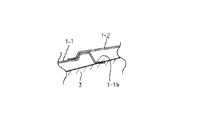
さらに、前記と同様に複数枚の金属瓦1をその端部を前後左右に重ね合わせて屋根を葺く場合、前後方向において下になる金属瓦1−1の上端のフランジ1−1bが水平状態に切断したままであるため、図13のように施工時に屋根下地3や他の屋根材を傷付けるおそれがあった。
【0008】
【発明が解決しようとする課題】
本発明の解決しようとする主たる課題は、金属屋根材の前記利点はそのままに、殊に施工時等における踏み潰しを防止でき、強風等による剥がれに強く、また雨水の浸入を完全に阻止でき、更に屋根下地の湿気を極力抑えることのできる金属屋根材を提供することにある。
【0009】
【課題を解決するための手段】
上記課題を解決するための本発明金属屋根材は、金属製薄板により、左右方向に適宜間隔で並行に複数の凸状直線体を断面積が大なるものと小なるものを交互に配設するよう形成され、且つ該凸状直線体の前後には他の同一屋根材との連結部を形成するとともに、該連結部を屋根材の屋根への施工時上になる側では、支持及び各凸状直線体の連絡のために上に凸な連絡路として形成され、また下になる側には、隣合う屋根材の前記連絡路を覆って嵌合する嵌合体として形成し、更に前記複数の凸状直線体の上下には開口部を設け、その開口部の上側は下側より開口面積を小としたことを特徴とするものである。
【0010】
【発明の実施の形態】
本発明の好ましい実施の形態を、図1乃至図8により説明すると、本発明金属屋根材10は、金属製薄板により、左右方向に適宜間隔で並行に複数の凸状直線体11を断面積が大なるもの11−1と小なるもの11−2を交互に配設するよう形成され、且つ該凸状直線体11の前後には他の同一屋根材との連結部12、13を形成するとともに、該連結部12、13を屋根材の屋根への施工時上になる側では、支持及び各凸状直線体の連絡のために上に凸な連絡路14として形成され、また下になる側には、隣合う屋根材の前記連絡路を覆って嵌合する嵌合部15として形成し、更に前記複数の凸状直線体の上下には通気口11a、12aを設け、その通気口の上側は下側より開口面積を小としたものである。
【0011】
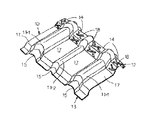
図1乃至図8に示す実施例について更に詳細に説明する。図1は本発明の金属屋根材10を施工時下になる側から見た状態を示し、図2は同じく施工時上になる側から見た状態を示すが、薄鋼板上に2本の断面積の大きな凸状直線体11−1とその間に断面積の小さな凸状直線体11−2が各々並行に形成されており、それらの間と両側には平坦部17が形成されている。
【0012】
前記凸状直線体11−1及び11−2の一方の端部には、連結部12となる連絡路14が前記各凸状直線体11−1及び11−2の端部を左右方向に連絡して形成され、また、他方の端部には連結部13となる嵌合部15が形成されている。前記連絡路14のフランジ14aには、図2に示すように前記凸状直線体11−1及び11−2に通ずる通気口11−1a及び11−2aが形成されている。図中18は連絡路14の外面に交差して形成された水切り用突部である。
【0013】
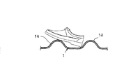
前記凸状直線体11−1及び11−2の断面形状は、図3に示すように、凸状直線体11−1では3つの角部をもつ山形、また凸状直線体11−2では1つの角部をもつ山形をそれぞれ成し、それらの間及び両側に平坦部17が設けられており、このように凸状直線体11−1及び11−2を山形にすることにより、剛性が高く雨水が溜まり難い直線体が得られる。
【0014】
また、2本の凸状直線体11−1のそれぞれから凸状直線体11−2の間の距離は、図3に示すように作業者の靴等が少なくとも大小の凸状直線体11−1、11−2に架かるような距離に設定するが、作業態様から考察すれば、靴の幅方向で必ず凸状直線体11−1または11−2にかかるのが望ましい。。
【0015】
本発明に係る金属屋根材10の連結部12となる連絡路14の端部フランジ14aには、傷付け防止用反り14bが形成されており、施工の際に屋根下地3に傷を付けたり、あるいは金属屋根材10同士間での傷を付け合うことを防止している。
【0016】
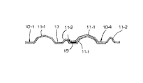
上記の如き金属屋根材10−1、10−2、10−3、…を用いて金属屋根構造を形成しようとするときは、左右方向には図6に示すように、例えば金属屋根材10−1と同屋根材10−4の互いに隣り合う凸状直線体11−1を、必要あればシール19を挟んで重ね合わせる。
【0017】
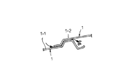
また、金属屋根構造の前後方向には、図4、図5、図7及び図8に示すように、例えば金属屋根材10−1の連結部12となる連絡路14の端部フランジ14aをビス16により屋根下地3に固定するとともに、同屋根材10−1の連結部13となる嵌合部15を直ぐ下の金属屋根材の連絡路14に被せ、下端を長いビス16’により金属屋根材10−2及びその直ぐ下の金属屋根材を共に屋根下地3に固定する。同様に、金属屋根材10−2、10−3、…と組上げて行けば、図7をさらに横に拡大した如き金属屋根構造が完成する。
【0018】
また、前記金属屋根材10−1、10−2、10−3、…の組付けにより、各凸状直線体11−1、11−2が下から上まで連続するので、その内部に対流通気システムが構成され、屋根下地3の湿気を減少させることができる。
【0019】
即ち、該システムは、金属屋根構造と屋根下地3の間の空気を凸状直線体11−1、11−2及び連絡路14を介して対流作用を利用して上方に移動せしめるようにしたもので、図7に示すように、太陽熱によって温められた金属屋根構造と屋根下地3の間の空気は、太矢印のように断面大なる凸状直線体11−1を上昇する間に通気口11−1aの出口で絞られて徐々に流速を増し、これによって小断面の凸状直線体11−2内及び平坦部17下の空気を引き入れて上昇し、金属屋根構造の上端から放出される。これにより金属屋根構造と屋根下地3の間の空気の澱みをなくし、屋根下地3の湿気を減少させるとともに、夏期における屋根裏の温度を下げる効果も期待できる。
【0020】
上記の如く構成された本発明金属屋根材は、先ず作業者が屋根材を踏んだとき、例えば大きな断面をもつ凸状直線体11−1と小さな断面を持つ凸状直線体11−2間に足が架かるので体重が分散されるとともに、体重は角部をもつ山形の剛性の高い凸状直線体11−1、11−2に支持され、また図4に明示するビス16’にも支持されることにより、凸状直線体11−1、11−2に変形を生ずることはない。
【0021】
また、前記のように金属屋根構造とするとき、上の金属屋根材10−2の連結部13の端部を、下の金属屋根材10−1とともにビス16’により屋根下地3に固定したので、前記体重によるほか強風等による金属屋根材の引き剥がし作用に対しても十分耐えうる。
【0022】
さらに、前記連絡路14に、前記嵌合体15の内部に接触する部分において水切り用突部18を交差して形成したので、図5に示すように、金属屋根材10の前後方向において、強風雨で連絡路14と嵌合部15のすき間から矢印のように雨水が浸入しようとしても、水切り用突部18によって阻止される。
【0023】
また金属屋根材10の左右方向においても、図6に示すように、強風雨で重ね合わせた凸状直線体11−1のすき間から矢印のように雨水が浸入しようとしても、角部のある山形形状およびシール19によって阻止される。
【0024】
【発明の効果】
本発明の金属屋根材は、金属製薄板により、左右方向に適宜間隔で並行に複数の凸状直線体を断面積が大なるものと小なるものを交互に配設するよう形成され、且つ該凸状直線体の前後には他の同一屋根材との連結部を形成するとともに、該連結部を屋根材の屋根への施工時上になる側では、支持及び各凸状直線体の連絡のために上に凸な連絡路として形成され、また下になる側には、隣合う屋根材の前記連絡路を覆って嵌合する嵌合体として形成し、更に前記複数の凸状直線体の上下には通気口を設け、その通気口の上側は下側より開口面積を小としたことを特徴とするので、まず断面積の大なる凸状直線体と小なる凸状直線体とを交互に適宜間隔で配設したことにより、体重が分散されて凸状直線体の踏み潰しが防止できる。この場合、凸状直線体の断面形状として角部のある山形としたものでは剛性が高くなり一層効果がある。
【0025】
また、複数の凸状直線体の上下には通気口を設け、その通気口の上側は下側より開口面積を小としたので、金属屋根板を組み合わせた金属屋根構造と屋根下地の間の空気は、断面大なる凸状直線体を上昇する間に通気口の出口で絞られて徐々に流速を増し、これによって小断面の凸状直線体内及び平坦部下の空気を引き入れて上昇し、金属屋根構造の上端から放出される。これにより金属屋根構造と屋根下地の間の空気の澱みをなくし、屋根下地の湿気を減少させるとともに、夏期における屋根裏の温度を下げる効果も期待できる。
【0026】
また、前記連絡路の断面形状が、前記嵌合体の内部に接触する部分において水切り用突部を交差して形成したものでは、前後方向において強風雨等で浸入しようとする雨水を完全に防止できる。
【0027】
また、凸状直線体の断面形状として角部のある山形としたものでは、複数の角部によって、左右方向における強風時の雨水の浸入を阻止できる。
【0028】
また、前記連結部における連絡路を形成する側の端部に傷付け防止用反りを設けたものでは、金属屋根材による施工時または金属屋根材の運搬時の傷付けを防止できる。
【図面の簡単な説明】
【図1】本発明金属屋根材の斜視図で、施工時の下側からみたもの
【図2】本発明金属屋根材の斜視図で、施工時の上側からみたもの
【図3】本発明金属屋根材の要部横断面略図で、力の分散状況も示すもの
【図4】本発明金属屋根構造の要部縦断面略図
【図5】本発明金属屋根構造の連結状態を示す部分的縦断面図
【図6】本発明金属屋根構造の連結状態を示す部分的横断面図
【図7】本発明金属屋根構造を示す斜視図で、併せて空気の対流状況を示す図
【図8】本発明金属屋根構造における金属屋根材の連絡路のフランジ部分を示す断面略図
【図9】従来の金属屋根材の要部横断面略図で、力の集中状況も示すもの
【図10】従来の金属屋根構造の要部縦断面略図
【図11】従来の金属屋根構造の連結状態を示す部分的縦断面図
【図12】従来の金属屋根構造の連結状態を示す部分的横断面図
【図13】従来の金属屋根構造における金属屋根材の連絡路のフランジ部分を示す断面略図。
【符号の説明】
1、1−1、1−2、1−3 金属瓦 1a ストレート部
2−1、2−2、16、16’ ビス 3 屋根下地 1−1b フランジ
10、10−1、10−2、10−3、10−4、 金属屋根材
11、11−1、11−2 凸状直線体 11−1a、11−2a 通気口 12、13 連結部 14 連絡路 14a フランジ 14b 傷付け防止用反り 15 嵌合部 17 平坦部 18 水切り用突部 19 シール。[0001]
BACKGROUND OF THE INVENTION
The present invention relates to a metal roof material formed from a steel plate or the like.
[0002]
[Prior art]
The metal roofing material, for example, a metal roof tile, has attracted attention as an alternative to conventional roof tiles in recent years because of its advantages of being lightweight, high in strength, inexpensive and easy to install, and is particularly used for the purpose of improving the earthquake resistance of buildings. It became so.
[0003]
However, the conventional metal roof tile is provided with the same semi-cylindrical straight portion (corresponding to the convex linear body in the present invention) at an appropriate interval as shown in, for example, Japanese Patent No. 2624194. Since 1a actually has a gentle chevron-shaped cross section as shown in FIG. 9, when the
[0004]
Conventionally, as shown in FIG. 10, the upper end of the lower metal tile 1-1 is directly fixed to the
[0005]
Further, when a plurality of
[0006]
Similarly, when a plurality of
[0007]
Further, when the roof of a plurality of
[0008]
[Problems to be solved by the invention]
The main problem to be solved by the present invention is that the above-mentioned advantages of the metal roofing material can be kept intact, in particular, it can be prevented from being crushed during construction, strong against peeling due to strong winds, etc., and intrusion of rainwater can be completely prevented, Furthermore, it is providing the metal roof material which can suppress the moisture of a roof base | substrate as much as possible .
[0009]
[Means for Solving the Problems]
The metal roofing material of the present invention for solving the above-mentioned problems is formed by alternately arranging a plurality of convex linear bodies having a large cross-sectional area and a small one in parallel in the left-right direction at appropriate intervals by a thin metal plate. In addition, a connecting portion with other same roofing material is formed before and after the convex linear body, and on the side where the connecting portion is at the time of construction on the roof of the roofing material, the supporting and protruding portions are formed. Formed as an upwardly projecting communication path for communication between the straight linear bodies, and formed on the lower side as a fitting body that covers and covers the communication path of the adjacent roof material, and An opening is provided above and below the convex linear body, and the opening area of the upper side of the opening is smaller than the lower side .
[0010]
DETAILED DESCRIPTION OF THE INVENTION
A preferred embodiment of the present invention will be described with reference to FIGS. 1 to 8. The
[0011]
The embodiment shown in FIGS. 1 to 8 will be described in more detail. FIG. 1 shows the state of the
[0012]
At one end of the convex linear bodies 11-1 and 11-2, a connecting
[0013]
As shown in FIG. 3, the cross-sectional shape of the convex linear bodies 11-1 and 11-2 is a mountain shape having three corners in the convex linear body 11-1, and 1 in the convex linear body 11-2. Each of them has a chevron with two corners, and
[0014]
Also, the distance between each of the two convex linear bodies 11-1 and the convex linear body 11-2 is such that the operator's shoes are at least large and small convex linear bodies 11-1 as shown in FIG. , 11-2 is set to a distance that spans the convex linear body 11-1 or 11-2 in the width direction of the shoe. .
[0015]
The
[0016]
When the metal roof structure is to be formed using the metal roof materials 10-1, 10-2, 10-3,... As described above, as shown in FIG. 1 and the adjacent convex linear bodies 11-1 of the same roofing material 10-4 are overlapped with a
[0017]
Further, in the front-rear direction of the metal roof structure, as shown in FIGS. 4, 5, 7, and 8, for example, an
[0018]
Moreover, since each convex linear body 11-1, 11-2 continues from the bottom to the top by the assembly of the metal roof materials 10-1, 10-2, 10-3,... A system is constructed, and the humidity of the
[0019]
That is, the system moves the air between the metal roof structure and the
[0020]
The metal roofing material of the present invention configured as described above, when an operator steps on the roofing material, for example, between a convex linear body 11-1 having a large cross section and a convex linear body 11-2 having a small cross section. The weight is dispersed because the legs are laid, and the weight is supported by the convex straight linear bodies 11-1 and 11-2 having a corner and having high rigidity, and is also supported by the screw 16 'clearly shown in FIG. Thus, the convex linear bodies 11-1 and 11-2 are not deformed.
[0021]
Moreover, when it is set as a metal roof structure as mentioned above, since the edge part of the
[0022]
Further, since the draining
[0023]
Also in the left-right direction of the
[0024]
【The invention's effect】
The metal roofing material of the present invention is formed by a thin metal plate so that a plurality of convex linear bodies are alternately arranged in parallel in the left-right direction at appropriate intervals, and the ones having a large cross-sectional area are alternately arranged. At the front and back of the convex linear body, a connecting portion with other same roofing material is formed, and on the side where the connecting portion is on when the roofing material is installed on the roof, support and communication of each convex linear body are made. In order to form a connecting path that is convex upward, and on the lower side, it is formed as a fitting body that covers and fits the connecting path of the adjacent roofing material, and further above and below the plurality of convex linear bodies. Is provided with a vent, and the upper side of the vent is characterized by having a smaller opening area than the lower side, so first the convex linear body with a large cross-sectional area and the small convex linear body alternately By arranging them at appropriate intervals, the weight is dispersed and the convex linear body can be prevented from being crushed. In this case, if the cross-sectional shape of the convex linear body is a mountain shape with corners, the rigidity becomes higher and the effect is further improved.
[0025]
In addition, air vents are provided above and below the plurality of convex linear bodies, and the upper area of the air vents has a smaller opening area than the lower side, so the air between the metal roof structure combined with the metal roof plate and the roof base While the convex straight body having a large cross section is raised, it is throttled at the outlet of the vent to gradually increase the flow velocity. Released from the top of the structure. This eliminates air stagnation between the metal roof structure and the roof base, reduces the humidity of the roof base, and can also be expected to lower the temperature of the attic in the summer.
[0026]
In addition, when the cross-sectional shape of the communication path is formed by intersecting the draining protrusion at the portion contacting the inside of the fitting body, it is possible to completely prevent rainwater from entering due to strong wind and rain in the front-rear direction. .
[0027]
In addition, in the case where the cross-sectional shape of the convex linear body is a mountain shape with corners, the plurality of corners can prevent the intrusion of rainwater in a strong wind in the left-right direction.
[0028]
Moreover, in the thing which provided the curvature for damage prevention in the edge part by the side which forms the connection path in the said connection part, the damage at the time of construction by a metal roof material or the conveyance of a metal roof material can be prevented.
[Brief description of the drawings]
FIG. 1 is a perspective view of the metal roofing material of the present invention as viewed from the lower side during construction. FIG. 2 is a perspective view of the metal roofing material of the present invention as viewed from the upper side during construction. Fig. 4 is a schematic cross-sectional view of the main part of the roofing material and also shows the distribution of force. Fig. 4 is a schematic vertical cross-sectional view of the main part of the metal roof structure of the present invention. FIG. 6 is a partial cross-sectional view showing the connected state of the metal roof structure of the present invention. FIG. 7 is a perspective view showing the metal roof structure of the present invention and also shows the convection state of air. Fig. 9 is a schematic cross-sectional view showing a flange portion of a connecting path of a metal roof material in a metal roof structure. Fig. 9 is a schematic cross-sectional view of a main part of a conventional metal roof material and also shows a concentration state of force. Fig. 10 is a conventional metal roof structure. FIG. 11 is a partial vertical cross-sectional view showing a connection state of a conventional metal roof structure. Schematic cross sectional view showing a flange portion of the communication passage of the metal roofing in partial cross-sectional view [FIG. 13] conventional metal roof construction showing the connection state of the conventional metal roof construction.
[Explanation of symbols]
DESCRIPTION OF
Claims (4)
Priority Applications (1)
| Application Number | Priority Date | Filing Date | Title |
|---|---|---|---|
| JP2002055052A JP3942016B2 (en) | 2002-02-28 | 2002-02-28 | Metal roofing material |
Applications Claiming Priority (1)
| Application Number | Priority Date | Filing Date | Title |
|---|---|---|---|
| JP2002055052A JP3942016B2 (en) | 2002-02-28 | 2002-02-28 | Metal roofing material |
Publications (2)
| Publication Number | Publication Date |
|---|---|
| JP2003253817A JP2003253817A (en) | 2003-09-10 |
| JP3942016B2 true JP3942016B2 (en) | 2007-07-11 |
Family
ID=28665990
Family Applications (1)
| Application Number | Title | Priority Date | Filing Date |
|---|---|---|---|
| JP2002055052A Expired - Fee Related JP3942016B2 (en) | 2002-02-28 | 2002-02-28 | Metal roofing material |
Country Status (1)
| Country | Link |
|---|---|
| JP (1) | JP3942016B2 (en) |
Family Cites Families (7)
| Publication number | Priority date | Publication date | Assignee | Title |
|---|---|---|---|---|
| JPS5164524U (en) * | 1974-11-16 | 1976-05-21 | ||
| JPH0732714Y2 (en) * | 1989-04-25 | 1995-07-31 | 株式会社動宣 | Metal roof |
| JPH05346053A (en) * | 1992-06-16 | 1993-12-27 | Sekisui Chem Co Ltd | Roof structure for building |
| JP2846580B2 (en) * | 1994-05-26 | 1999-01-13 | 有限会社田村創研 | Roofing structure using metal shingles |
| JP2624194B2 (en) * | 1994-09-12 | 1997-06-25 | 株式会社動宣 | Metal roof tile |
| JP2788874B2 (en) * | 1995-08-01 | 1998-08-20 | 大阪鉄建協同組合 | Tile rod square wave plate |
| JP2000110305A (en) * | 1998-10-02 | 2000-04-18 | Shinko Kogyo Kk | Tile roof material made of metal and execution method thereof |
-
2002
- 2002-02-28 JP JP2002055052A patent/JP3942016B2/en not_active Expired - Fee Related
Also Published As
| Publication number | Publication date |
|---|---|
| JP2003253817A (en) | 2003-09-10 |
Similar Documents
| Publication | Publication Date | Title |
|---|---|---|
| US6463708B1 (en) | Roof shingle and system | |
| JPH058304B2 (en) | ||
| JP3942016B2 (en) | Metal roofing material | |
| US8776480B2 (en) | Vented nail base roof assembly and associated method | |
| JPH0415864B2 (en) | ||
| JP2011252361A (en) | Ventilation ridge | |
| JP3799155B2 (en) | Solar panel installation structure | |
| JPH108621A (en) | Flat roof structure | |
| JP4571449B2 (en) | Ventilation building | |
| JPH0245702Y2 (en) | ||
| JP3618070B2 (en) | Roof with solar cells | |
| JP2013032621A (en) | Ventilation water table | |
| JP5424040B2 (en) | Attic ventilation structure | |
| US20080134604A1 (en) | Roof ventilation system for tiled roof | |
| JP2000064541A (en) | Wing ventilation structure | |
| JP6962542B2 (en) | Kasagi structure | |
| JP2818928B2 (en) | Roof structure | |
| JP3241167B2 (en) | Cabinet for air conditioner | |
| JPH0781374B2 (en) | Roof waterproof ventilation structure | |
| JP3078957B2 (en) | Parapet panel with no snowfall roof | |
| JP4520076B2 (en) | Flat ridge structure of the roof | |
| JP4824991B2 (en) | Insulated roof structure | |
| JP2818927B2 (en) | Unit roof panels and roof structures | |
| JPH10131441A (en) | Roof mounting panel | |
| JPS6129856Y2 (en) |
Legal Events
| Date | Code | Title | Description |
|---|---|---|---|
| A621 | Written request for application examination |
Free format text: JAPANESE INTERMEDIATE CODE: A621 Effective date: 20050207 |
|
| A977 | Report on retrieval |
Free format text: JAPANESE INTERMEDIATE CODE: A971007 Effective date: 20061128 |
|
| A131 | Notification of reasons for refusal |
Free format text: JAPANESE INTERMEDIATE CODE: A131 Effective date: 20061212 |
|
| A521 | Written amendment |
Free format text: JAPANESE INTERMEDIATE CODE: A523 Effective date: 20070213 |
|
| TRDD | Decision of grant or rejection written | ||
| A01 | Written decision to grant a patent or to grant a registration (utility model) |
Free format text: JAPANESE INTERMEDIATE CODE: A01 Effective date: 20070327 |
|
| A61 | First payment of annual fees (during grant procedure) |
Free format text: JAPANESE INTERMEDIATE CODE: A61 Effective date: 20070329 |
|
| R150 | Certificate of patent or registration of utility model |
Ref document number: 3942016 Country of ref document: JP Free format text: JAPANESE INTERMEDIATE CODE: R150 Free format text: JAPANESE INTERMEDIATE CODE: R150 |
|
| FPAY | Renewal fee payment (event date is renewal date of database) |
Free format text: PAYMENT UNTIL: 20100413 Year of fee payment: 3 |
|
| FPAY | Renewal fee payment (event date is renewal date of database) |
Free format text: PAYMENT UNTIL: 20110413 Year of fee payment: 4 |
|
| R250 | Receipt of annual fees |
Free format text: JAPANESE INTERMEDIATE CODE: R250 |
|
| FPAY | Renewal fee payment (event date is renewal date of database) |
Free format text: PAYMENT UNTIL: 20120413 Year of fee payment: 5 |
|
| R250 | Receipt of annual fees |
Free format text: JAPANESE INTERMEDIATE CODE: R250 |
|
| FPAY | Renewal fee payment (event date is renewal date of database) |
Free format text: PAYMENT UNTIL: 20130413 Year of fee payment: 6 |
|
| R250 | Receipt of annual fees |
Free format text: JAPANESE INTERMEDIATE CODE: R250 |
|
| FPAY | Renewal fee payment (event date is renewal date of database) |
Free format text: PAYMENT UNTIL: 20130413 Year of fee payment: 6 |
|
| FPAY | Renewal fee payment (event date is renewal date of database) |
Free format text: PAYMENT UNTIL: 20140413 Year of fee payment: 7 |
|
| R250 | Receipt of annual fees |
Free format text: JAPANESE INTERMEDIATE CODE: R250 |
|
| R250 | Receipt of annual fees |
Free format text: JAPANESE INTERMEDIATE CODE: R250 |
|
| R250 | Receipt of annual fees |
Free format text: JAPANESE INTERMEDIATE CODE: R250 |
|
| R250 | Receipt of annual fees |
Free format text: JAPANESE INTERMEDIATE CODE: R250 |
|
| R250 | Receipt of annual fees |
Free format text: JAPANESE INTERMEDIATE CODE: R250 |
|
| R250 | Receipt of annual fees |
Free format text: JAPANESE INTERMEDIATE CODE: R250 |
|
| LAPS | Cancellation because of no payment of annual fees |