JP3950004B2 - Inkjet recording apparatus and inkjet recording method - Google Patents
Inkjet recording apparatus and inkjet recording method Download PDFInfo
- Publication number
- JP3950004B2 JP3950004B2 JP2002126039A JP2002126039A JP3950004B2 JP 3950004 B2 JP3950004 B2 JP 3950004B2 JP 2002126039 A JP2002126039 A JP 2002126039A JP 2002126039 A JP2002126039 A JP 2002126039A JP 3950004 B2 JP3950004 B2 JP 3950004B2
- Authority
- JP
- Japan
- Prior art keywords
- electric field
- driving electric
- chamber
- ejection
- ink
- Prior art date
- Legal status (The legal status is an assumption and is not a legal conclusion. Google has not performed a legal analysis and makes no representation as to the accuracy of the status listed.)
- Expired - Fee Related
Links
- 238000000034 method Methods 0.000 title claims description 28
- 230000005684 electric field Effects 0.000 claims description 190
- 239000000919 ceramic Substances 0.000 claims description 31
- 230000007423 decrease Effects 0.000 claims description 7
- 238000010586 diagram Methods 0.000 description 10
- 230000000052 comparative effect Effects 0.000 description 7
- 239000000758 substrate Substances 0.000 description 6
- 238000007796 conventional method Methods 0.000 description 3
- 230000000694 effects Effects 0.000 description 3
- 230000010287 polarization Effects 0.000 description 3
- 238000007599 discharging Methods 0.000 description 2
- 230000000149 penetrating effect Effects 0.000 description 2
- XLYOFNOQVPJJNP-UHFFFAOYSA-N water Substances O XLYOFNOQVPJJNP-UHFFFAOYSA-N 0.000 description 2
- 239000000853 adhesive Substances 0.000 description 1
- 230000001070 adhesive effect Effects 0.000 description 1
- 229910052782 aluminium Inorganic materials 0.000 description 1
- XAGFODPZIPBFFR-UHFFFAOYSA-N aluminium Chemical compound [Al] XAGFODPZIPBFFR-UHFFFAOYSA-N 0.000 description 1
- 238000005452 bending Methods 0.000 description 1
- 239000003086 colorant Substances 0.000 description 1
- 239000007788 liquid Substances 0.000 description 1
- 229910052751 metal Inorganic materials 0.000 description 1
- 239000002184 metal Substances 0.000 description 1
- 229920001721 polyimide Polymers 0.000 description 1
- 230000002940 repellent Effects 0.000 description 1
- 239000005871 repellent Substances 0.000 description 1
- 230000000087 stabilizing effect Effects 0.000 description 1
- 238000007740 vapor deposition Methods 0.000 description 1
Images


Classifications
-
- B—PERFORMING OPERATIONS; TRANSPORTING
- B41—PRINTING; LINING MACHINES; TYPEWRITERS; STAMPS
- B41J—TYPEWRITERS; SELECTIVE PRINTING MECHANISMS, i.e. MECHANISMS PRINTING OTHERWISE THAN FROM A FORME; CORRECTION OF TYPOGRAPHICAL ERRORS
- B41J2202/00—Embodiments of or processes related to ink-jet or thermal heads
- B41J2202/01—Embodiments of or processes related to ink-jet heads
- B41J2202/10—Finger type piezoelectric elements
Landscapes
- Particle Formation And Scattering Control In Inkjet Printers (AREA)
Description
【0001】
【発明の属する技術分野】
本発明は、例えば、プリンタ、ファックスなどに適用されるインクジェット式記録装置及びインクジェット式記録方法に関する。
【0002】
【従来の技術】
従来より、インクを吐出する複数のノズルを有するインクジェットヘッドを用いて被記録媒体に文字や画像を記録するインクジェット式記録装置が知られている。かかるインクジェット式記録装置では、インクジェットヘッドのノズルが被記録媒体に対向するようにヘッドホルダに設けられ、このヘッドホルダはキャリッジに搭載され被記録媒体の搬送方向とは直交する方向に走査されるようになっている。
【0003】
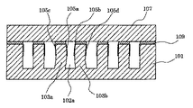
このようなインクジェットヘッドのヘッドチップの一例の分解概略を図13に、また、要部断面を図14に示す。
【0004】
図13及び図14に示すように、圧電セラミックプレート101には、複数のチャンバ102が並設され、各チャンバ102は、側壁103で分離されている。各チャンバ102の長手方向一端部は圧電セラミックプレート101の一端面まで延設されており、他端部は、他端面までは延びておらず、深さが徐々に浅くなっている。このような各チャンバ102内の両側壁103の開口側表面には、長手方向に亘って、駆動電界印加用の電極105が形成されている。
【0005】
また、圧電セラミックプレート101のチャンバ102の開口側には、カバープレート107が接着剤109を介して接合されている。このカバープレート107には、各チャンバ102の浅くなった他端部と連通する凹部となる共通インク室111と、この共通インク室111の底部からチャンバ102とは反対方向に貫通するインク供給口112とを有する。
【0006】
さらに、圧電セラミックプレート101とカバープレート107との接合体のチャンバ102が開口している端面には、ノズルプレート115が接合されており、ノズルプレート115の各チャンバ102に対向する位置にはノズル開口117が形成されている。
【0007】
なお、圧電セラミックプレート101のノズルプレート115とは反対側でカバープレート107とは反対側の面には、配線基板120が固着されている。配線基板120には、各電極105とボンディングワイヤ121等で接続された配線122が形成され、この配線122を介して電極105に駆動電圧を印加できるようになっている。
【0008】
このように構成されるヘッドチップでは、インク供給口112から各チャンバ102内にインクを充填し、所定のチャンバ102の両側の側壁103に電極105を介して所定の駆動電界を作用させると、側壁103が撓み変形してチャンバ102内の容積が一時的に変化し、これにより、チャンバ102内のインクがノズル開口117から吐出する。
【0009】
例えば、図15に示すように、チャンバ102aに対応するノズル開口117からインクを吐出する場合には、そのチャンバ102a内の電極105a、105bに正の駆動電圧を印加すると共にそれぞれに対向する電極105c、105dを接地するようにする。これにより、側壁103a、103bにはチャンバ102aに向かう方向の駆動電界が作用し、これが圧電セラミックプレート101の分極方向と直交すれば、圧電厚みすべり効果により側壁103a、103bがチャンバ102a方向に撓み変形し、チャンバ102a内の容積が減少してインクに対する圧力が増加し、ノズル開口117からインクが吐出する。
【0010】
【発明が解決しようとする課題】
しかしながら、上述した従来のインクジェット式記録装置に搭載されるインクジェットヘッドでは、チャンバの並び方向の位置、インク滴の吐出数、あるいはインク滴の吐出頻度等の吐出率の違いによって、各インク滴の吐出量、吐出スピード等の吐出特性にばらつきが生じてしまうという問題がある。
【0011】
例えば、インクジェットヘッドの端部側に配置されたチャンバと、その他の位置に配置されたチャンバとでは、インク滴の吐出スピードに差が生じるという問題がある。また、所定のチャンバに連通するノズル開口から複数のインク滴を連続的に吐出する場合と、待機状態のチャンバに連通するノズル開口からインク滴を単発的に吐出する場合とでは、インク滴の吐出スピードに差が生じてしまうという問題がある。さらに、全ノズル開口からインク滴を吐出する場合と、所定のノズル開口から単発的にインク滴を吐出する場合とでは、インク滴の吐出量に差が生じてしまうという問題がある。
【0012】
また、このような問題は、低温環境下、すなわち、インクの粘度が比較的高いと特に発生しやすい。
【0013】
本発明は、このような事情に鑑み、各ノズル開口から吐出されるインクの吐出特性を安定させることができるインクジェット記録装置及びインクジェット式記録方法を提供することを課題とする。
【0014】
【課題を解決するための手段】
上記課題を解決する本発明の第1の態様は、圧電セラミックプレートにノズル開口に連通し且つインクの充填されたチャンバを複数並設すると共に各チャンバの両側の側壁に電極が設けられたインクジェットヘッドを具備し、前記電極を介して前記側壁に前記チャンバ内の容積を一時的に増大させる予備駆動電界と当該予備駆動電界に連続し前記チャンバ内の容積を一時的に減少させる吐出駆動電界とからなる駆動電界を発生させることでインクを吐出させるインクジェット式記録装置において、インクを吐出させる所定のチャンバ以外のその他のチャンバでインクを吐出可能な少なくとも一つの待機チャンバの少なくとも一方の側壁に、前記予備駆動電界に対応して当該予備駆動電界と同一方向で発生され且つ当該予備駆動電界よりも発生期間の短い非吐出予備駆動電界を少なくとも含む待機駆動電界を発生させる待機駆動信号を、前記駆動電界を発生させる駆動信号と共に出力する駆動手段を具備することを特徴とするインクジェット式記録装置にある。
【0015】
本発明の第2の態様は、第1の態様において、前記非吐出予備駆動電界のピークが、前記予備駆動電界のピークと略同一であることを特徴とするインクジェット式記録装置にある。
【0016】
本発明の第3の態様は、第1又は2の態様において、前記予備駆動電界の発生期間をxとし、前記予備駆動電界と前記吐出駆動電界との間隔をyとしたときに、前記吐出駆動電界の発生期間が2x−yで表される長さであることを特徴とするインクジェット式記録装置にある。
【0017】
本発明の第4の態様は、第1〜3の何れかの態様において、前記非吐出予備駆動電界の発生期間が、前記予備駆動電界の発生期間の1/2以下であることを特徴とするインクジェット式記録装置にある。
【0018】
本発明の第5の態様は、第4の態様において、前記非吐出予備駆動電界の発生期間が、前記予備駆動電界の発生期間の1/10以下であることを特徴とするインクジェット式記録装置にある。
【0019】
本発明の第6の態様は、第1〜5の何れかの態様において、前記待機駆動電界が、前記吐出駆動電界に対応して当該吐出駆動電界と同一方向で発生される非吐出駆動電界を含むことを特徴とするインクジェット式記録装置にある。
【0020】
本発明の第7の態様は、第1〜6の何れかの態様において、前記待機駆動電界は、インクを吐出する直前の待機チャンバに対応して発生させることを特徴とするインクジェット式記録装置にある。
【0021】
本発明の第8の態様は、第1〜6の何れかの態様において、前記待機駆動電界は、全ての待機チャンバに対応して発生させることを特徴とするインクジェット式記録装置にある。
【0022】
本発明の第9の態様は、第1〜8の何れかの態様において、前記待機駆動電界は、前記待機チャンバの両方の側壁に対応して発生させることを特徴とするインクジェット式記録装置にある。
【0023】
本発明の第10の態様は、第1〜9の何れかの態様において、前記待機駆動電界は、前記待機チャンバの一方の側壁のみに対応して発生させることを特徴とするインクジェット式記録装置にある。
【0024】
本発明の第11の態様は、第1〜10の何れかの態様において、前記電極の全てが、前記駆動信号又は前記待機駆動信号が独立して出力される個別電極であることを特徴とするインクジェット式記録装置にある。
【0025】
本発明の第12の態様は、第1〜10の何れかの態様において、前記チャンバ内の相対向する一対の電極が、前記駆動信号又は前記待機駆動信号が出力される一対の個別電極であることを特徴とするインクジェット式記録装置にある。
【0026】
本発明の第13の態様は、第1〜10の何れかの態様において、前記チャンバのそれぞれの間に、前記インクの充填されないダミーチャンバが設けられ該ダミーチャンバ内の側壁に前記電極が設けられていることを特徴とするインクジェット式記録装置にある。
【0027】
本発明の第14の態様は、圧電セラミックプレートにノズル開口に連通し且つインクの充填されたチャンバを複数並設すると共に各チャンバの両側の側壁に電極が設けられたインクジェットヘッドを具備し、前記電極を介して前記側壁に前記チャンバ内の容積を一時的に増大させる予備駆動電界と当該予備駆動電界に連続し前記チャンバ内の容積を一時的に減少させる吐出駆動電界とからなる駆動電界を発生させることでインクを吐出させるインクジェット式記録方法において、インクを吐出させる所定のチャンバ以外のその他のチャンバでインクを吐出可能な少なくとも一つの待機チャンバの少なくとも一方の側壁に、前記予備駆動電界に対応して当該予備駆動電界と同一方向で発生され且つ当該予備駆動電界よりも発生期間の短い非吐出予備駆動電界を少なくとも含む待機駆動電界を発生させる待機駆動信号を、前記駆動電界を発生させる駆動信号と共に出力することを特徴とするインクジェット式記録方法にある。
【0028】
本発明の第15の態様は、第14の態様において、前記非吐出予備駆動電界のピークが、前記予備駆動電界のピークと略同一であることを特徴とするインクジェット式記録方法にある。
【0029】
本発明の第16の態様は、第14又は15の態様において、前記予備駆動電界の発生期間をxとし、前記予備駆動電界と前記吐出駆動電界との間隔をyとしたときに、前記吐出駆動電界の発生期間が2x−yで表される長さとすることを特徴とするインクジェット式記録方法にある。
【0030】
本発明の第17の態様は、第14〜16の何れかの態様において、前記非吐出予備駆動電界の発生期間が、前記予備駆動電界の発生期間の1/2以下であることを特徴とするインクジェット式記録方法にある。
【0031】
本発明の第18の態様は、第17の態様において、前記非吐出予備駆動電界の発生期間が、前記予備駆動電界の発生期間の1/10以下であることを特徴とするインクジェット式記録方法にある。
【0032】
本発明の第19の態様は、第14〜18の何れかの態様において、前記非吐出駆動電界が、前記吐出駆動電界に対応して当該吐出駆動電界と同一方向で発生される非吐出駆動電界を含むことを特徴とするインクジェット式記録方法にある。
【0033】
本発明の第20の態様は、第14〜19の何れかの態様において、前記非吐出駆動電界は、インクを吐出する直前の待機チャンバに対応して発生させることを特徴とするインクジェット式記録方法にある。
【0034】
本発明の第21の態様は、第14〜19の何れかの態様において、前記非吐出駆動電界は、全ての待機チャンバに対応して発生させることを特徴とするインクジェット式記録方法にある。
【0035】
本発明の第22の態様は、第14〜21の何れかの態様において、前記非吐出駆動電界を、前記待機チャンバの両方の側壁に対応して発生させることを特徴とするインクジェット式記録方法にある。
【0036】
本発明の第23の態様は、第14〜21の何れかの態様において、前記非吐出駆動電界を、前記待機チャンバの片側の側壁のみに対応して発生させることを特徴とするインクジェット式記録方法にある。
【0037】
かかる本発明では、インクを吐出させない待機チャンバの側壁に待機駆動電界を発生させることで、インクを吐出させる直前のチャンバの状態を常に一定の状態に維持できるため、各ノズル開口から吐出されるインクの吐出特性が安定する。
【0038】
【発明の実施の形態】
以下に本発明を実施形態に基づいて詳細に説明する。
【0039】
(実施形態1)
図1は、本発明の実施形態1に係るインクジェット式記録装置の概略図である。
【0040】
図1に示すように、本実施形態のインクジェット式記録装置10は、ヘッドが走査されるシリアル方式のインクジェット式記録装置であり、インクを吐出させるインクジェットヘッド20が設けられたヘッドユニット100を具備する。このヘッドユニット100はキャリッジ11上に固定されており、キャリッジ11は一対のガイドレール12a、12b上に軸方向に移動自在に搭載されている。
【0041】
また、ガイドレール12a、12bの一端側には駆動モータ13が設けられており、この駆動モータ13による駆動力が、当該駆動モータ13に連結されたプーリ14aと、ガイドレール12a、12bの他端側に設けられたプーリ14bとの間に掛け渡されたタイミングベルト15に沿って移動されるようになっている。
【0042】
さらに、キャリッジ11の搬送方向と直交する方向の両端部側には、ガイドレール12a、12bに沿ってそれぞれ一対の搬送ローラ16、17が設けられている。これらの搬送ローラ16、17は、キャリッジ11の下方に当該キャリッジ11の搬送方向とは直交する方向に被記録媒体Sを搬送するものである。
【0043】
そして、これら搬送ローラ16、17によって被記録媒体Sを送りつつキャリッジ11をその送り方向とは直交方向に走査することにより、インクジェットヘッド20によって被記録媒体S上に文字及び画像等が記録される。
【0044】
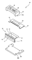
ここで、インクを吐出させるインクジェットヘッドの一例について説明する。なお、図2は、本発明の実施形態1に係るインクジェットヘッドの分解斜視図であり、図3は、ヘッドチップの分解斜視図であり、図4は、インクジェットヘッドの組立工程を示す概略斜視図である。
【0045】
図2に示すように、本実施形態のインクジェットヘッド20は、ヘッドチップ21と、このヘッドチップ21の一方面側に設けられるベースプレート22と、ヘッドチップ21の他方面側に設けられるヘッドカバー23と、ヘッドチップ21を駆動するための駆動回路24が搭載された配線基板25とを有する。
【0046】
まず、ヘッドチップ21について詳しく説明する。図3及び図4に示すように、ヘッドチップ21を構成する圧電セラミックプレート26には、ノズル開口27に連通してインクを吐出させるチャンバ28が複数並設され、各チャンバ28は、側壁29で分離されている。
【0047】
各チャンバ28の長手方向一端部は、圧電セラミックプレート26の一端面まで延設されており、他端部は、他端面までは延びておらず、深さが徐々に浅くなっている。なお、各チャンバ28は、例えば、円盤状のダイスカッターにより形成され、深さが徐々に浅くなった部分は、ダイスカッターの形状を利用して形成される。
【0048】
また、各チャンバ28内の両側の側壁28の開口側表面には、長手方向に亘って、チャンバ28毎に独立した駆動信号が出力される一対の個別電極30がそれぞれ形成されている。この一対の個別電極30は、例えば、公知の斜め方向からの蒸着によって各チャンバ28内の各側壁29にそれぞれ形成される。
【0049】
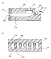
さらに、圧電セラミックプレート26のチャンバ28の開口側には、インク室プレート31が接合されている。このインク室プレート31には、各チャンバ28の浅くなった他端部のみと連通する凹部となるインク室32と、このインク室32の底部からチャンバ28とは反対方向に貫通するインク供給口33とが設けられている。
【0050】
ここで、本実施形態では、各チャンバ28は、ブラック(B)、イエロー(Y)、マゼンダ(M)、シアン(C)の各色のインクに対応したグループに分かれており、インク室32及びインク供給口33は、それぞれ4つずつ設けられている。
【0051】
なお、インク室プレート31は、例えば、セラミックプレート、金属プレート等で形成することができるが、圧電セラミックプレート26との接合後の変形等を考えると、熱膨張率の近似したセラミックプレートを用いるのが好ましい。
【0052】
また、圧電セラミックプレート26とインク室プレート31の接合体とのチャンバ28が開口している端面には、ノズルプレート34が接合されている。このノズルプレート34の各チャンバ28に対向する位置にはノズル開口27が形成されている。
【0053】
さらに、ノズルプレート34は、圧電セラミックプレート26とインク室プレート31との接合体のチャンバ28が開口している端面の面積よりも大きくなっている。このノズルプレート34は、ポリイミドフィルムなどに、例えば、エキシマレーザ装置を用いてノズル開口27を形成したものである。また、図示しないが、ノズルプレート34の被印刷物に対向する面には、インクの付着等を防止するために撥水性を有する撥水膜が設けられている。
【0054】
なお、本実施形態では、圧電セラミックプレート26とインク室プレート31との接合体のチャンバ28が開口している端部の周囲には、ノズル支持プレート35が配置されている。このノズル支持プレート35は、ノズルプレート34の接合体端面の外側と接合されて、ノズルプレート34を安定して保持するためのものである。
【0055】
ここで、このようなヘッドチップ21を具備するインクジェットヘッド20について詳細に説明する。
【0056】
図2及び図4に示すように、インクジェットヘッド20は、ヘッドチップ21を構成する圧電セラミックプレート26のノズル開口27側とは反対側の端部に、例えば、ボンディングワイヤ等を介して一対の個別電極30に接続される図示しない配線パターンが形成されている。
【0057】
また、圧電セラミックプレート26とインク室プレート31との接合体のノズル支持プレート35の後端側には、圧電セラミックプレート26側のアルミニウム製のベースプレート22と、インク室プレート31側のヘッドカバー23とが組み付けられる。このヘッドカバー23には、インク室プレート31のインク供給口33のそれぞれに連通するインク導入路36が設けられている。
【0058】
そして、ベースプレート22及びヘッドカバー23は、ベースプレート22の係止孔22aにヘッドカバー23の係止シャフト23aを係合することにより固定され、両者で圧電セラミックプレート26とインク室プレート31との接合体を挟持する。
【0059】
また、図4(a)に示すように、圧電セラミックプレート26の後端側に突出したベースプレート22上には配線基板25が固着されている。この配線基板25上には、ヘッドチップ21を駆動するための駆動ICを有する駆動回路24が搭載され、後述する駆動回路24とフレキシブルケーブルとが異方性導電膜37を介して接続される。これにより、図4(b)のインクジェットヘッド20が完成する。
【0060】
さらに、上述したインクジェットヘッド20は、インクカートリッジを保持するタンクホルダ40に組み付けられてヘッドユニット100が形成される。
【0061】
ここで、インクジェットヘッド20を組み付けるタンクホルダ40の一例について図5を参照して説明する。なお、図5は、本実施形態に係るタンクホルダの一例を示す概略斜視図である。
【0062】
図5に示すように、タンクホルダ40は、一方面が開口した略箱形形状を有し、インクカートリッジが着脱自在に保持可能なものである。
【0063】
また、タンクホルダ40の底壁上面には、インクカートリッジの底部に形成された開口部と、インク導入路36とを連結させる連結部41が設けられている。この連結部41は、例えば、ブラック(B)、イエロー(Y)、マゼンダ(M)、シアン(C)の各色のインク毎に設けられている。
【0064】
さらに、連結部41内には図示しないインク流路が形成され、その開口となる連結部41の先端には、フィルタ42が設けられている。
【0065】
この連結部41内に形成されたインク流路は、底壁の裏面側まで連通して形成されており、各インク流路は、タンクホルダ40の裏面側に設けられた流路基板43の側壁に開口するヘッド連結口44に連通している。
【0066】
また、タンクホルダ40の側面には、上述したインクジェットヘッド20を保持固定するヘッド保持部45が設けられている。
【0067】
このようなヘッド保持部45には、配線基板25上に設けられた駆動回路24を包囲する略コ字状に立設された包囲壁46と、この包囲壁46内にあってインクジェットヘッド20のベースプレート22及び配線基板25に設けられた係止孔22bと係合する係合シャフト47が立設されている。
【0068】
そして、上述したタンクホルダ40のヘッド保持部45にインクジェットヘッド20が搭載されることでヘッドユニット100が完成する。このとき、ヘッドカバー23に形成されたインク導入路36は、流路基板43のヘッド連結口44に連結されている。
【0069】
ここで、各チャンバ28内の側壁29に設けられた一対の個別電極30に駆動信号を出力する駆動手段を駆動回路24に表して詳細に説明する。なお、図6は、駆動回路とヘッドチップとの配線の接続状態を示す概略図である。
【0070】
図6に示すように、駆動回路24には、外部からの電源と、印刷信号等の外部信号とからなる外部回路50とが外部配線51を介して接続されている。これにより、外部信号が外部配線51を介して外部回路50から駆動回路24に出力される。
【0071】
また、駆動回路24は、フレキシブルケーブル38を介して各チャンバ28内の側壁29に設けられた一対の個別電極30にそれぞれ接続されている。これにより、駆動回路24に入力された外部信号は、各チャンバ28内の一対の個別電極30に駆動信号としてそれぞれ出力されることになる。
【0072】
なお、本実施形態では、各チャンバ28の側壁29を形成する圧電セラミックプレート26の分極方向は、チャンバ28の底部からインク室プレート31側に向かって各側壁29が突出する方向と同一方向である。
【0073】
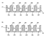
ここで、インクジェット式記録装置10の駆動方法について詳細に説明する。なお、図7は、圧電セラミックプレートの断面図及び一対の個別電極に付与される駆動波形を示す図であり、図8は、駆動波形の詳細を説明する図であり、図9は、チャンバの両側の側壁の動きを説明する圧電セラミックプレートの断面図である。
【0074】
図7に示す駆動波形60a〜60fは、各チャンバ28a〜28f内の一対の電極30にそれぞれ印加される駆動電圧を示す。また、駆動波形61は、駆動波形60a〜60cによってチャンバ28bの両側の側壁29a、29bに発生させる駆動電界を示す。また、駆動波形62は、駆動波形60d〜60fによってチャンバ28eの両側の側壁29d、29eに発生させる駆動電界を示す。
【0075】
本実施形態では、このような駆動波形61、62によってチャンバ28b(ノズル開口27)からインク滴を吐出後、連続してチャンバ28b、28eからインク滴を吐出させるようになっている。すなわち、チャンバ28bからインク滴を吐出させる場合は、チャンバ28eはインクを吐出しない待機状態となり、この待機状態から続いてチャンバ28b、28eから同時にインク滴を吐出させるようになっている。
【0076】
さらに、本実施形態のインク滴を吐出させるための駆動電界は、チャンバ28b、28e内の容積を一時的に増大させる予備駆動電界と、予備駆動電界に連続してチャンバ28b、28e内の容積を一時的に減少させる吐出駆動電界とからなる。なお、予備駆動電界は、駆動波形61のA及びE領域と駆動波形62のE領域とで表され、吐出駆動電界は、駆動波形61のC及びG領域と駆動波形62のG領域とに表されている。
【0077】
ここで、このような予備駆動電界と吐出駆動電界とのそれぞれの発生期間は、次の関係を満たしていることが好ましい。すなわち、図8に示すように、予備駆動電界の発生期間をxとし、予備駆動電界の発生期間と吐出駆動電界の発生期間との間隔をyとしたときに、吐出駆動電界の発生期間が2x−yで表される長さであることが好ましい。これにより、各ノズル開口27からインク滴を良好に吐出することができる。
【0078】
一方、駆動波形61のC領域に表された吐出駆動電界によってチャンバ28bからインク滴を吐出させる場合、本実施形態では、待機状態のチャンバ28eの両側の側壁29d、29eに駆動波形60d〜60eによってチャンバ28eからインク滴を吐出させない程度の待機駆動電界(駆動波形62のA〜C領域)を発生させている。
【0079】
このような待機駆動電界は、本実施形態では、予備駆動電界に対応して予備駆動電界と同一方向で発生され且つ予備駆動電界よりも発生期間の短い非吐出予備駆動電界と、吐出駆動電界に対応して吐出駆動電界と同一方向で発生される非吐出駆動電界とからなる。なお、非吐出予備駆動電界は、駆動波形62のA領域に表されている。また、非吐出駆動電界は、駆動波形62のC領域で表されており、本実施形態では、チャンバ28bからインクを吐出させた吐出駆動電界(駆動波形61のC領域)と同一の駆動電界としている。
【0080】
ここで、非吐出予備駆動電界の発生期間は、予備駆動電界の発生期間の1/2以下、特に、1/10以下であることが好ましく、1/18とするのが最適である。これにより、非吐出駆動電界との組み合わせによっても、インク滴が誤吐出されることなく、所定の側壁に電界を発生させることができる。
【0081】
また、非吐出予備駆動電界のピークは、予備駆動電界のピークと略同一であることが好ましい。これにより、予備駆動電界の発生期間を変更することのみで、非吐出予備駆動電界を容易に発生させることができる。
【0082】
以下、インクを吐出させる際の各チャンバの両側の側壁の動きについて詳細に説明する。
【0083】
インク滴が吐出されるチャンバ28bでは、印刷信号の入力に伴い、駆動波形60bのA領域でチャンバ28b内の一対の個別電極30に予備駆動電圧が印加されて、チャンバ28bの両側の側壁29a、29bに予備駆動電界が発生する。これにより、チャンバ28bの各側壁29a、29bが、その略中央部が外側に向かって離れるように撓み変形してチャンバ28b内の容積を一時的に増大させる(図9(a)参照)。
【0084】
このとき、チャンバ28e内の一対の個別電極30には非吐出予備駆動電圧が印加されて、チャンバ28eの両側の側壁29d、29eには予備駆動電界よりも発生期間が短い非吐出予備駆動電界が発生する。これにより、チャンバ28eの各側壁29d、29eも、その略中央部が外側に向かって離れるように撓み変形するが、その変形量はチャンバ28bの側壁29a、29bよりも小さい。
【0085】
続いて、駆動波形60a、60cのC領域でチャンバ28a、28c内に設けられた一対の個別電極30に吐出駆動電圧が印加され、チャンバ28bの両側の側壁29a、29bに吐出駆動電界が発生する。これにより、チャンバ28bの各側壁29a、29bの略中央部が内側に向かって近接するように撓み変形してチャンバ28b内の容積が増大している状態から一時的に減少し、ノズル開口27からインク滴が吐出される(図9(b)参照)。
【0086】
一方、チャンバ28bの各側壁29a、29bに吐出駆動電界を発生させたのと同時に、駆動波形60d、60fのC領域では、チャンバ28d、28f内の一対の個別電極30に、チャンバ28a、28c内の一対の個別電極30に印加される吐出駆動電圧と同等の非吐出駆動電圧が印加されることで、チャンバ28eの両側の側壁29d、29eに非吐出駆動電界を発生させている。これにより、チャンバ28eの各側壁29d、29eの略中央部が内側に向かって近接するように撓み変形してチャンバ28b内の容積が増大している状態から、容積が一時的に減少する(図9(b)参照)。このとき、チャンバ28eの非吐出予備駆動電界による容積の増加量が、チャンバ28bの予備駆動電界による増加量よりも小さいため、チャンバ28e内に充填されたインクは、チャンバ28eから吐出されることはない。
【0087】
その後、インク滴を吐出させたチャンバ28bの両側の側壁29a、29bに駆動波形61のE及びG領域で表される予備駆動電界と吐出駆動電界とを発生させると共に、待機状態のチャンバ28eの両側の側壁29d、29eに駆動波形62のE及びG領域で表される予備駆動電界と吐出駆動電界とを発生させることにより、チャンバ28b、28e内からインク滴がそれぞれ同時に吐出される。
【0088】
このように、チャンバ28bからインク滴を吐出させた際に、待機状態としたチャンバ28eの両側の側壁29d、29eにインク滴を吐出させない程度の待機駆動電界(非吐出予備駆動電界及び非吐出駆動電界)を発生させることにより、次のインク滴の吐出時には、インク滴を吐出させたチャンバ28bと待機状態のチャンバ28eとが同じ状態に保持されるため、各チャンバ28b、28eから吐出されるインクの吐出特性は略同一となる。
【0089】
以上説明したように、待機状態にあるチャンバ28eの側壁29d、29eに待機駆動電界を発生させておくことにより、インク滴を吐出させる直前の各チャンバの状態を均一に保持することができるため、インク滴を連続して吐出させるチャンバ28bと、待機状態からインク滴を吐出させるチャンバ28eとのインク吐出特性が均一化される。
【0090】
すなわち、一度に複数のインク滴を吐出する場合と、比較的少ない数のインク滴を吐出する場合とでのインク吐出特性の差が小さく抑えられる。また、インク吐出時の各チャンバ28の状態を一定に保持できるため、チャンバ28の並設方向の位置の違いによるインク吐出特性のばらつきも防止することができる。
【0091】
したがって、各ノズル開口からは、常に安定した吐出量及び吐出スピードでインク滴が吐出され、常に良好な印刷品質を得ることができる。
【0092】
なお、本実施形態では、待機状態のチャンバ28eの側壁29d、29eに、非吐出予備駆動電界と非吐出駆動電界とからなる待機駆動電界を発生させるようにしたが、これに限定されず、例えば、図10に示すように、駆動波形60d〜60fによって非吐出予備駆動電界のみからなる待機駆動電界(駆動波形62のA〜C領域)を発生させるようにしてもよい。
【0093】
また、本実施形態では、待機状態のチャンバの両側の側壁に待機駆動電界を発生させるようにしたが、これに限定されず、少なくとも一方の側壁に発生させればよい。
【0094】
さらに、待機駆動電界は、インクを吐出させる直前の待機状態のチャンバのみに選択的に発生させるようにしてもよいが、全ての待機状態のチャンバに常に発生させるようにしてもよい。
【0095】
このように全ての待機状態のチャンバに常に待機駆動電界を発生させることにより、低温環境下であってもインク粘度の上昇による吐出不良を防止することができる。これは、インクを吐出する際には、常に全てのチャンバ28の側壁29に電界が変形されることにより、インクの温度を上昇させてインクの粘度を低下させることができるからである。また、このように待機駆動電界を発生させることによってインクの粘度を低下させることができるため、比較的粘度の高いインクも用いることができ、インクの選択範囲が広がる。
【0096】
ここで、下記の各実施例及び比較例のインクジェット式記録装置においてそれぞれインク滴を吐出させ、チャンバ(ノズル開口)の配列位置とインク吐出スピードとの関係を調べた。その結果を図11(a)に示す。
【0097】
(実施例1)
実施例1のインクジェット式記録装置では、所定のチャンバからインク滴を吐出させる際に、待機チャンバの側壁に非吐出予備駆動電界と非吐出駆動電界とからなる待機駆動電界を発生させた。
【0098】
(実施例2)
実施例2のインクジェト式記録装置は、所定のチャンバからインク滴を吐出させる際に、待機チャンバの側壁に非吐出予備駆動電界のみからなる待機駆動電界を発生させるようにした以外は、実施例1のインクジェット式記録装置と同様である。
【0099】
(比較例1)
比較例1のインクジェット式記録装置は、所定のチャンバからインク滴を吐出させる際に、待機チャンバの側壁に待機駆動電界を発生させることなく停止状態とした以外は、実施例1のインクジェット式記録装置と同様である。
【0100】
図11(a)のグラフに示すように、実施例1及び2のインクジェット式記録装置では、各ノズル開口から吐出されるインク滴の吐出スピードの差が比較的小さい。これに対し、比較例1のインクジェット式記録装置では、ヘッドの端部側に設けられたノズル開口(ノズル番号1)から吐出されたインク滴の吐出スピードだけが、他のノズル開口から吐出されたインク滴の吐出スピードよりも明らかに速くなっていることが分かる。
【0101】
この結果から明らかなように、本発明のインクジェット式記録装置によれば、チャンバの配列位置に拘わらず、安定したインク吐出特性が得られる。
【0102】
次に、上記の実施例1及び比較例1のインクジェット式記録ヘッドを用いて、全ノズル開口からインク滴を吐出させた場合のインク滴の吐出量と、1つのノズル開口からインク滴を吐出させた場合とのインク滴の吐出量との差を調べた。その結果を図11(b)に示す。
【0103】
図11(b)のグラフから明らかなように、実施例1のインクジェット式記録装置では、全ノズルからインク滴を吐出させた場合と、1つのノズル開口からインク滴を吐出させた場合とのインク滴の吐出量は、駆動電圧に拘わらずほぼ一致している。これに対し、比較例1のインクジェット式記録ヘッドでは、1つのノズル開口からインク滴を吐出させた場合、全ノズル開口からインク滴を吐出させた場合と比較して、何れの駆動電圧でもインク滴の吐出量が20%以上低下していることが分かる。
【0104】
この結果から明らかなように、本発明のインクジェット式記録ヘッドでは、一度に吐出するインク滴の数に拘わらず、安定したインク吐出特性が得られる。
【0105】
(他の実施形態)
以上、本発明の一実施形態について説明したが、本発明はこのような構成に限定されるものではない。
【0106】
例えば、上述の本実施形態では、各チャンバ28a〜28f内の側壁29に一対の個別電極30を設けたインクジェットヘッドを例示して説明したが、本発明のインクジェット式記録装置に搭載されるインクジェットヘッドはこれに限定されるものではない。
【0107】
例えば、図12に示すように、各チャンバ28a〜28fの側壁29a〜29eに駆動信号がそれぞれ独立して出力される個別電極30Aを設けたタイプのインクジェットヘッドであってもよい。
【0108】
また、例えば、インクの充填されるチャンバのそれぞれの間にインクの充填されないダミーチャンバが設けられたタイプのインクジェットヘッドであってもよい。なお、このタイプのインクジェットヘッドは、各チャンバの両側の側壁の分極方向が、上述のタイプのインクジェットヘッドとは逆方向となる。
【0109】
このような何れのタイプのインクジェットヘッドを用いた場合であっても、待機状態のチャンバの側壁に待機駆動電界を発生させてインクを吐出させない程度にチャンバを容積変化させることにより、上述した実施形態と同様の効果を得ることができる。
【0110】
また、上述した実施形態では、インクジェットヘッドを走査するシリアル型のインクジェット式記録装置を例示して説明したが、本発明は、インクジェットヘッドが固定されたライン型のインクジェット式記録装置等の他のタイプのインクジェット式記録装置にも適用することができる。
【0111】
【発明の効果】
以上説明したように、本発明によれば、インクを吐出させない待機チャンバの少なくとも一方の側壁に駆動電界と同一方向で且つ待機チャンバからインクを吐出させない程度で且つ予備駆動電界に対応して発生されこの予備駆動電界よりも発生期間の短い非吐出予備駆動電界を少なくとも含む待機駆動電界を発生させるようにしたので、インクを吐出する際の各チャンバが略均一な状態に保持される。したがって、各チャンバから吐出されるインクの吐出安定性を向上できる。
【図面の簡単な説明】
【図1】本発明の実施形態1に係るインクジェット式記録装置の概略図である。
【図2】本発明の実施形態1に係るインクジェットヘッドの分解斜視図である。
【図3】本発明の実施形態1に係るヘッドチップの分解斜視図である。
【図4】本発明の実施形態1に係るインクジェットヘッドの組立工程を示す斜視図である。
【図5】本発明の実施形態1に係るタンクホルダの一例を示す概略斜視図である。
【図6】本発明の実施形態1に係るインクジェット式記録ヘッドの概略構成を示す図である。
【図7】本発明の実施形態1に係る圧電セラミックプレートの断面図及び一対の個別電極に付与される駆動波形を示す図である。
【図8】本発明の実施形態1に係る駆動波形を示す図である。
【図9】本発明の実施形態1に係るチャンバの両側の動きを説明する圧電セラミックプレートの断面図である。
【図10】本発明の実施形態1に係る圧電セラミックプレートの断面図及び一対の個別電極に付与される駆動波形の他の例を示す図である。
【図11】各実施例及び比較例のインクジェット式記録装置でのインク吐出特性を示すグラフである。
【図12】本発明の他の実施形態に係るインクジェット式記録装置の概略構成を示す図である。
【図13】従来技術に係るインクジェットヘッドのヘッドチップの概要を示す概略斜視図である。
【図14】従来技術に係るインクジェットヘッドのヘッドチップの概要を示す断面図である。
【図15】従来技術に係るインクジェットヘッドのヘッドチップの概要を示す断面図である。
【符号の説明】
10 インクジェット式記録装置
20 インクジェットヘッド
21 ヘッドチップ
22 ベースプレート
23 ヘッドカバー
24 駆動回路
25 配線基板
26 圧電セラミックプレート
27 ノズル開口
28、28a〜28f チャンバ
29、29a〜29e 側壁
30 一対の個別電極
30A 個別電極
34 ノズルプレート
40 タンクホルダ
50 外部回路
51 外部配線
60a〜60f、61、62 駆動波形
100 ヘッドユニット[0001]
BACKGROUND OF THE INVENTION
The present invention relates to an ink jet recording apparatus and an ink jet recording method applied to, for example, a printer and a fax machine.
[0002]
[Prior art]
2. Description of the Related Art Conventionally, an ink jet recording apparatus that records characters and images on a recording medium using an ink jet head having a plurality of nozzles that eject ink is known. In such an ink jet recording apparatus, the nozzle of the ink jet head is provided in the head holder so as to face the recording medium, and this head holder is mounted on the carriage so as to be scanned in a direction orthogonal to the transport direction of the recording medium. It has become.
[0003]
An outline of an example of a head chip of such an ink jet head is shown in FIG. 13, and a cross section of the main part is shown in FIG.
[0004]
As shown in FIGS. 13 and 14, a plurality of
[0005]
A
[0006]
Further, a
[0007]
A
[0008]
In the head chip configured as described above, when each
[0009]
For example, as shown in FIG. 15, when ink is ejected from the
[0010]
[Problems to be solved by the invention]
However, in the ink jet head mounted on the above-described conventional ink jet recording apparatus, each ink droplet is ejected due to a difference in ejection rate such as the position in the chamber alignment direction, the number of ink droplet ejection, or the frequency of ink droplet ejection. There is a problem that variation occurs in ejection characteristics such as volume and ejection speed.
[0011]
For example, there is a problem in that there is a difference in ink droplet ejection speed between a chamber disposed on the end side of the inkjet head and a chamber disposed at another position. Ink droplet ejection is performed when a plurality of ink droplets are continuously ejected from a nozzle opening communicating with a predetermined chamber and when ink droplets are ejected only once from a nozzle opening communicating with a standby chamber. There is a problem that a difference occurs in speed. Furthermore, there is a problem in that there is a difference in the amount of ink droplets ejected between the case where ink droplets are ejected from all nozzle openings and the case where ink droplets are ejected only once from predetermined nozzle openings.
[0012]
Such a problem is particularly likely to occur in a low temperature environment, that is, when the viscosity of the ink is relatively high.
[0013]
In view of such circumstances, it is an object of the present invention to provide an ink jet recording apparatus and an ink jet recording method capable of stabilizing the discharge characteristics of ink discharged from each nozzle opening.
[0014]
[Means for Solving the Problems]
A first aspect of the present invention that solves the above problems is an ink jet head in which a plurality of chambers filled with ink are connected to a piezoelectric ceramic plate in parallel with nozzle openings, and electrodes are provided on both side walls of each chamber. A preliminary driving electric field that temporarily increases the volume in the chamber on the side wall via the electrode, and a discharge driving electric field that continues to the preliminary driving electric field and temporarily decreases the volume in the chamber. In the ink jet recording apparatus for ejecting ink by generating a driving electric field, the spare is provided on at least one side wall of at least one standby chamber capable of ejecting ink in a chamber other than the predetermined chamber for ejecting ink. Corresponding to the driving electric field, it is generated in the same direction as the preliminary driving electric field and is generated from the preliminary driving electric field. A short waiting driving signal the non-ejection preliminary driving electric field to generate a standby driving electric field including at least between, there is provided an ink jet recording apparatus, characterized by comprising a driving unit for outputting the driving signal to generate the driving electric field.
[0015]
According to a second aspect of the present invention, in the first aspect, the peak of the non-ejection preliminary driving electric field is substantially the same as the peak of the preliminary driving electric field.
[0016]
According to a third aspect of the present invention, in the first or second aspect, the ejection driving is performed when the generation period of the preliminary driving electric field is x and the interval between the preliminary driving electric field and the ejection driving electric field is y. In the ink jet recording apparatus, the generation period of the electric field has a length represented by 2x-y.
[0017]
According to a fourth aspect of the present invention, in any one of the first to third aspects, the generation period of the non-ejection preliminary driving electric field is ½ or less of the generation period of the preliminary driving electric field. In an inkjet recording apparatus.
[0018]
According to a fifth aspect of the present invention, in the ink jet recording apparatus according to the fourth aspect, the generation period of the non-ejection preliminary driving electric field is 1/10 or less of the generation period of the preliminary driving electric field. is there.
[0019]
According to a sixth aspect of the present invention, in any one of the first to fifth aspects, the standby driving electric field is a non-ejection driving electric field generated in the same direction as the ejection driving electric field corresponding to the ejection driving electric field. An ink jet recording apparatus including the ink jet recording apparatus.
[0020]
A seventh aspect of the present invention is the ink jet recording apparatus according to any one of the first to sixth aspects, wherein the standby driving electric field is generated corresponding to a standby chamber immediately before ink is ejected. is there.
[0021]
An eighth aspect of the present invention is the ink jet recording apparatus according to any one of the first to sixth aspects, wherein the standby drive electric field is generated corresponding to all standby chambers.
[0022]
A ninth aspect of the present invention is the ink jet recording apparatus according to any one of the first to eighth aspects, wherein the standby drive electric field is generated corresponding to both side walls of the standby chamber. .
[0023]
A tenth aspect of the present invention is the ink jet recording apparatus according to any one of the first to ninth aspects, wherein the standby drive electric field is generated corresponding to only one side wall of the standby chamber. is there.
[0024]
According to an eleventh aspect of the present invention, in any one of the first to tenth aspects, all of the electrodes are individual electrodes to which the drive signal or the standby drive signal is independently output. In an inkjet recording apparatus.
[0025]
According to a twelfth aspect of the present invention, in any one of the first to tenth aspects, the pair of opposed electrodes in the chamber is a pair of individual electrodes to which the drive signal or the standby drive signal is output. The present invention is an ink jet recording apparatus.
[0026]
According to a thirteenth aspect of the present invention, in any one of the first to tenth aspects, a dummy chamber not filled with the ink is provided between the chambers, and the electrode is provided on a side wall of the dummy chamber. The present invention is an ink jet recording apparatus.
[0027]
A fourteenth aspect of the present invention includes an inkjet head in which a plurality of chambers filled with ink are provided in parallel with a nozzle opening in a piezoelectric ceramic plate and electrodes are provided on side walls on both sides of each chamber. A drive electric field including a pre-driving electric field that temporarily increases the volume in the chamber and an ejection driving electric field that is continuous with the pre-driving electric field and temporarily reduces the volume in the chamber is generated on the side wall via the electrode. In the ink jet recording method in which ink is discharged, at least one side wall of at least one standby chamber capable of discharging ink in a chamber other than the predetermined chamber from which ink is discharged corresponds to the preliminary driving electric field. Non-ejection generated in the same direction as the preliminary driving electric field and having a shorter generation period than the preliminary driving electric field The standby driving signals for generating the standby driving electric field including at least a Bei driving electric field, in an ink jet recording method and outputs the driving signal to generate the driving electric field.
[0028]
A fifteenth aspect of the present invention is the ink jet recording method according to the fourteenth aspect, wherein the peak of the non-ejection preliminary driving electric field is substantially the same as the peak of the preliminary driving electric field.
[0029]
According to a sixteenth aspect of the present invention, in the fourteenth or fifteenth aspect, the ejection driving is performed when the generation period of the preliminary driving electric field is x and the interval between the preliminary driving electric field and the ejection driving electric field is y. The ink jet recording method is characterized in that the generation period of the electric field has a length represented by 2x-y.
[0030]
According to a seventeenth aspect of the present invention, in any one of the fourteenth to sixteenth aspects, the generation period of the non-ejection preliminary drive electric field is ½ or less of the generation period of the preliminary drive electric field. In the ink jet recording method.
[0031]
An eighteenth aspect of the present invention is the ink jet recording method according to the seventeenth aspect, wherein the generation period of the non-ejection preliminary driving electric field is 1/10 or less of the generation period of the preliminary driving electric field. is there.
[0032]
According to a nineteenth aspect of the present invention, in any one of the fourteenth to eighteenth aspects, the non-ejection driving electric field is generated in the same direction as the ejection driving electric field corresponding to the ejection driving electric field. An ink jet recording method comprising:
[0033]
A twentieth aspect of the present invention is the ink jet recording method according to any one of the fourteenth to nineteenth aspects, wherein the non-ejection drive electric field is generated corresponding to a standby chamber immediately before ink ejection. It is in.
[0034]
A twenty-first aspect of the present invention is the ink jet recording method according to any one of the fourteenth to nineteenth aspects, wherein the non-ejection driving electric field is generated corresponding to all the standby chambers.
[0035]
A twenty-second aspect of the present invention is the ink-jet recording method according to any one of the fourteenth to twenty-first aspects, wherein the non-ejection driving electric field is generated corresponding to both side walls of the standby chamber. is there.
[0036]
A twenty-third aspect of the present invention is the ink-jet recording method according to any one of the fourteenth to twenty-first aspects, wherein the non-ejection driving electric field is generated corresponding to only one side wall of the standby chamber. It is in.
[0037]
In the present invention, since the standby drive electric field is generated on the side wall of the standby chamber where ink is not discharged, the state of the chamber immediately before the ink is discharged can always be kept constant, so that the ink discharged from each nozzle opening The discharge characteristics are stable.
[0038]
DETAILED DESCRIPTION OF THE INVENTION
Hereinafter, the present invention will be described in detail based on embodiments.
[0039]
(Embodiment 1)
FIG. 1 is a schematic diagram of an ink jet recording apparatus according to
[0040]
As shown in FIG. 1, an ink
[0041]
Further, a drive motor 13 is provided on one end side of the
[0042]
Further, a pair of
[0043]
The
[0044]
Here, an example of an inkjet head that ejects ink will be described. 2 is an exploded perspective view of the inkjet head according to the first embodiment of the present invention, FIG. 3 is an exploded perspective view of a head chip, and FIG. 4 is a schematic perspective view showing an assembly process of the inkjet head. It is.
[0045]
As shown in FIG. 2, the
[0046]
First, the
[0047]
One end of each
[0048]
In addition, a pair of
[0049]
Further, an
[0050]
Here, in the present embodiment, each
[0051]
The
[0052]
In addition, a
[0053]
Further, the
[0054]
In the present embodiment, the
[0055]
Here, the
[0056]
As shown in FIGS. 2 and 4, the
[0057]
An
[0058]
The
[0059]
As shown in FIG. 4A, a
[0060]
Further, the above-described
[0061]
Here, an example of the
[0062]
As shown in FIG. 5, the
[0063]
Further, on the upper surface of the bottom wall of the
[0064]
Furthermore, an ink flow path (not shown) is formed in the connecting
[0065]
The ink flow path formed in the connecting
[0066]
Further, on the side surface of the
[0067]
Such a
[0068]
The
[0069]
Here, driving means for outputting a driving signal to a pair of
[0070]
As shown in FIG. 6, the
[0071]
Further, the
[0072]
In this embodiment, the polarization direction of the piezoelectric
[0073]
Here, a driving method of the ink
[0074]
[0075]
In the present embodiment, ink droplets are continuously ejected from the
[0076]
Furthermore, the drive electric field for ejecting ink droplets of the present embodiment includes a preliminary drive electric field that temporarily increases the volume in the
[0077]
Here, it is preferable that the generation periods of the preliminary driving electric field and the ejection driving electric field satisfy the following relationship. That is, as shown in FIG. 8, when the preliminary drive electric field generation period is x and the interval between the preliminary drive electric field generation period and the discharge drive electric field generation period is y, the discharge drive electric field generation period is 2x. The length is preferably represented by -y. Thereby, ink droplets can be favorably ejected from each
[0078]
On the other hand, in the case where ink droplets are ejected from the
[0079]
In this embodiment, such a standby driving electric field is generated in the same direction as the preliminary driving electric field corresponding to the preliminary driving electric field, and is a non-ejection preliminary driving electric field that has a shorter generation period than the preliminary driving electric field, and an ejection driving electric field. Correspondingly, it comprises a non-ejection drive electric field generated in the same direction as the ejection drive electric field. Note that the non-ejection preliminary driving electric field is represented in the area A of the driving
[0080]
Here, the generation period of the non-ejection preliminary driving electric field is preferably ½ or less, particularly 1/10 or less of the generation period of the preliminary driving electric field, and is optimally 1/18. As a result, an electric field can be generated on a predetermined side wall without erroneous ejection of ink droplets even in combination with a non-ejection driving electric field.
[0081]
Moreover, it is preferable that the peak of the non-ejection preliminary driving electric field is substantially the same as the peak of the preliminary driving electric field. Thereby, the non-ejection preliminary driving electric field can be easily generated only by changing the generation period of the preliminary driving electric field.
[0082]
Hereinafter, the movement of the side walls on both sides of each chamber when ink is ejected will be described in detail.
[0083]
In the
[0084]
At this time, a non-ejection preliminary driving voltage is applied to the pair of
[0085]
Subsequently, a discharge drive voltage is applied to the pair of
[0086]
On the other hand, at the same time that the ejection drive electric field is generated on the
[0087]
Thereafter, a preliminary driving electric field and an ejection driving electric field represented by regions E and G of the driving
[0088]
As described above, when the ink droplets are ejected from the
[0089]
As described above, since the standby drive electric field is generated on the
[0090]
That is, the difference in ink ejection characteristics between when a plurality of ink droplets are ejected at a time and when a relatively small number of ink droplets are ejected can be suppressed. In addition, since the state of each
[0091]
Therefore, ink droplets are always ejected from each nozzle opening with a stable ejection amount and ejection speed, and a good print quality can always be obtained.
[0092]
In this embodiment, the standby drive electric field including the non-ejection preliminary drive electric field and the non-ejection drive electric field is generated on the
[0093]
In this embodiment, the standby drive electric field is generated on the side walls on both sides of the standby chamber. However, the present invention is not limited to this, and it may be generated on at least one of the side walls.
[0094]
Further, the standby drive electric field may be selectively generated only in the standby chamber immediately before ink is ejected, or may be generated constantly in all the standby chambers.
[0095]
Thus, by always generating a standby drive electric field in all the standby chambers, it is possible to prevent ejection failure due to an increase in ink viscosity even in a low temperature environment. This is because when the ink is ejected, the electric field is always deformed on the
[0096]
Here, in the ink jet recording apparatuses of the following examples and comparative examples, ink droplets were ejected, and the relationship between the arrangement position of the chamber (nozzle opening) and the ink ejection speed was examined. The result is shown in FIG.
[0097]
Example 1
In the ink jet recording apparatus of Example 1, when ejecting ink droplets from a predetermined chamber, a standby driving electric field composed of a non-ejection preliminary driving electric field and a non-ejection driving electric field is generated on the side wall of the standby chamber.
[0098]
(Example 2)
The ink jet recording apparatus according to the second embodiment is the same as the first embodiment except that a standby driving electric field including only a non-ejection preliminary driving electric field is generated on the side wall of the standby chamber when ejecting ink droplets from a predetermined chamber. This is the same as the ink jet recording apparatus.
[0099]
(Comparative Example 1)
The ink jet recording apparatus of Comparative Example 1 is the ink jet recording apparatus of Example 1 except that when ink droplets are ejected from a predetermined chamber, the ink jet recording apparatus is stopped without generating a standby driving electric field on the side wall of the standby chamber. It is the same.
[0100]
As shown in the graph of FIG. 11A, in the ink jet recording apparatuses of Examples 1 and 2, the difference in the ejection speed of the ink droplets ejected from each nozzle opening is relatively small. In contrast, in the ink jet recording apparatus of Comparative Example 1, only the ejection speed of the ink droplets ejected from the nozzle opening (nozzle number 1) provided on the end side of the head was ejected from the other nozzle openings. It can be seen that it is clearly faster than the ink droplet ejection speed.
[0101]
As is clear from this result, according to the ink jet recording apparatus of the present invention, stable ink ejection characteristics can be obtained regardless of the arrangement position of the chambers.
[0102]
Next, using the ink jet recording heads of Example 1 and Comparative Example 1 described above, the amount of ink droplets ejected from all nozzle openings and the ink droplets ejected from one nozzle opening. The difference between the amount of ink droplets discharged and the amount of ink droplets was examined. The result is shown in FIG.
[0103]
As is apparent from the graph of FIG. 11B, in the ink jet recording apparatus of Example 1, the ink when ink droplets are ejected from all nozzles and when ink droplets are ejected from one nozzle opening The droplet discharge amounts are almost the same regardless of the drive voltage. On the other hand, in the ink jet recording head of Comparative Example 1, when ink droplets are ejected from one nozzle opening, ink droplets are not generated at any driving voltage as compared to the case where ink droplets are ejected from all nozzle openings. It can be seen that the discharge amount of the liquid drops by 20% or more.
[0104]
As is clear from this result, the ink jet recording head of the present invention can provide stable ink ejection characteristics regardless of the number of ink droplets ejected at a time.
[0105]
(Other embodiments)
As mentioned above, although one Embodiment of this invention was described, this invention is not limited to such a structure.
[0106]
For example, in the above-described embodiment, the ink jet head in which the pair of
[0107]
For example, as shown in FIG. 12, it may be an ink jet head in which
[0108]
Further, for example, it may be an ink jet head of a type in which a dummy chamber not filled with ink is provided between each chamber filled with ink. In this type of inkjet head, the polarization directions of the side walls on both sides of each chamber are opposite to those of the above-described type of inkjet head.
[0109]
Regardless of which type of inkjet head is used, the above-described embodiment is achieved by changing the volume of the chamber to such an extent that a standby drive electric field is generated on the side wall of the standby chamber and ink is not discharged. The same effect can be obtained.
[0110]
In the above-described embodiment, the serial type ink jet recording apparatus that scans the ink jet head has been described as an example. However, the present invention is not limited to other types such as a line type ink jet recording apparatus to which the ink jet head is fixed. The present invention can also be applied to the inkjet recording apparatus.
[0111]
【The invention's effect】
As described above, according to the present invention, the ink is generated on the side wall of at least one of the standby chambers that does not discharge ink in the same direction as the drive electric field and at a level that does not discharge ink from the standby chamber and corresponding to the preliminary drive electric field. Since the standby driving electric field including at least the non-ejection preliminary driving electric field having a generation period shorter than the preliminary driving electric field is generated, the chambers for discharging the ink are maintained in a substantially uniform state. Therefore, the ejection stability of the ink ejected from each chamber can be improved.
[Brief description of the drawings]
FIG. 1 is a schematic diagram of an ink jet recording apparatus according to a first embodiment of the invention.
FIG. 2 is an exploded perspective view of the inkjet head according to the first embodiment of the invention.
FIG. 3 is an exploded perspective view of the head chip according to the first embodiment of the invention.
FIG. 4 is a perspective view illustrating an assembly process of the inkjet head according to the first embodiment of the invention.
FIG. 5 is a schematic perspective view showing an example of a tank holder according to
FIG. 6 is a diagram illustrating a schematic configuration of the ink jet recording head according to the first embodiment of the invention.
FIG. 7 is a cross-sectional view of the piezoelectric ceramic plate according to the first embodiment of the present invention and a diagram showing driving waveforms applied to a pair of individual electrodes.
FIG. 8 is a diagram showing drive waveforms according to the first embodiment of the present invention.
FIG. 9 is a cross-sectional view of a piezoelectric ceramic plate for explaining the movement of both sides of the chamber according to
FIG. 10 is a cross-sectional view of the piezoelectric ceramic plate according to the first embodiment of the present invention and another example of drive waveforms applied to a pair of individual electrodes.
FIG. 11 is a graph showing ink ejection characteristics in the ink jet recording apparatuses of Examples and Comparative Examples.
FIG. 12 is a diagram showing a schematic configuration of an ink jet recording apparatus according to another embodiment of the present invention.
FIG. 13 is a schematic perspective view showing an outline of a head chip of an inkjet head according to a conventional technique.
FIG. 14 is a cross-sectional view showing an outline of a head chip of an inkjet head according to a conventional technique.
FIG. 15 is a cross-sectional view showing an outline of a head chip of an inkjet head according to a conventional technique.
[Explanation of symbols]
10 Inkjet recording device
20 Inkjet head
21 Head chip
22 Base plate
23 Head cover
24 Drive circuit
25 Wiring board
26 Piezoelectric ceramic plate
27 Nozzle opening
28, 28a-28f Chamber
29, 29a-29e side wall
30 A pair of individual electrodes
30A individual electrode
34 Nozzle plate
40 Tank holder
50 External circuit
51 External wiring
60a-60f, 61, 62 Drive waveform
100 head unit
Claims (23)
Priority Applications (1)
| Application Number | Priority Date | Filing Date | Title |
|---|---|---|---|
| JP2002126039A JP3950004B2 (en) | 2002-04-26 | 2002-04-26 | Inkjet recording apparatus and inkjet recording method |
Applications Claiming Priority (1)
| Application Number | Priority Date | Filing Date | Title |
|---|---|---|---|
| JP2002126039A JP3950004B2 (en) | 2002-04-26 | 2002-04-26 | Inkjet recording apparatus and inkjet recording method |
Publications (2)
| Publication Number | Publication Date |
|---|---|
| JP2003311950A JP2003311950A (en) | 2003-11-06 |
| JP3950004B2 true JP3950004B2 (en) | 2007-07-25 |
Family
ID=29540581
Family Applications (1)
| Application Number | Title | Priority Date | Filing Date |
|---|---|---|---|
| JP2002126039A Expired - Fee Related JP3950004B2 (en) | 2002-04-26 | 2002-04-26 | Inkjet recording apparatus and inkjet recording method |
Country Status (1)
| Country | Link |
|---|---|
| JP (1) | JP3950004B2 (en) |
Families Citing this family (1)
| Publication number | Priority date | Publication date | Assignee | Title |
|---|---|---|---|---|
| JP4828889B2 (en) * | 2005-08-12 | 2011-11-30 | エスアイアイ・プリンテック株式会社 | Ink jet head driving method, ink jet head, and ink jet recording apparatus |
-
2002
- 2002-04-26 JP JP2002126039A patent/JP3950004B2/en not_active Expired - Fee Related
Also Published As
| Publication number | Publication date |
|---|---|
| JP2003311950A (en) | 2003-11-06 |
Similar Documents
| Publication | Publication Date | Title |
|---|---|---|
| JP3130291B2 (en) | Driving method of inkjet head | |
| EP0461939B1 (en) | Ink jet recording apparatus using heat generating element | |
| JPH05131622A (en) | Ink-jet recording device | |
| JP2002326354A (en) | Head chip | |
| JP2785727B2 (en) | Ink jet print head and driving method thereof | |
| JP2001246745A (en) | Inkjet recording head | |
| JP3950004B2 (en) | Inkjet recording apparatus and inkjet recording method | |
| JPH0462157A (en) | inkjet recording device | |
| JP3730165B2 (en) | Inkjet recording apparatus and recording method | |
| EP0461938B1 (en) | Ink jet recording method and ink jet recording apparatus using same | |
| JP3872336B2 (en) | Inkjet recording apparatus and inkjet recording method | |
| JP2001180015A (en) | Ink jet recording apparatus, ink jet recording method, and ink jet recording head | |
| JP2002144557A (en) | Driving method of inkjet head | |
| JP4763418B2 (en) | Ink jet head driving method, ink jet head, and ink jet recording apparatus | |
| JP4694727B2 (en) | Head chip unit and ink jet recording apparatus | |
| JP4717425B2 (en) | Inkjet recording apparatus and inkjet recording method | |
| JP3302401B2 (en) | Ink jet driving apparatus and ink jet driving method | |
| US7175245B2 (en) | Ink-jet head and ink-jet type recording apparatus | |
| JPH106518A (en) | Ink jet recording device | |
| JP2002326351A (en) | Head chip | |
| US7866776B2 (en) | Ink jet head driving method, ink jet head and ink jet recording apparatus | |
| JP2004001274A (en) | Ink jet head | |
| JP3221405B2 (en) | Inkjet recording head | |
| JP2984415B2 (en) | Ink jet recording device using heating element | |
| JP3025584B2 (en) | Ink jet recording device and ink cassette |
Legal Events
| Date | Code | Title | Description |
|---|---|---|---|
| RD01 | Notification of change of attorney |
Free format text: JAPANESE INTERMEDIATE CODE: A7421 Effective date: 20040309 |
|
| A621 | Written request for application examination |
Free format text: JAPANESE INTERMEDIATE CODE: A621 Effective date: 20041216 |
|
| A977 | Report on retrieval |
Free format text: JAPANESE INTERMEDIATE CODE: A971007 Effective date: 20070125 |
|
| A131 | Notification of reasons for refusal |
Free format text: JAPANESE INTERMEDIATE CODE: A131 Effective date: 20070130 |
|
| A521 | Written amendment |
Free format text: JAPANESE INTERMEDIATE CODE: A523 Effective date: 20070323 |
|
| TRDD | Decision of grant or rejection written | ||
| A01 | Written decision to grant a patent or to grant a registration (utility model) |
Free format text: JAPANESE INTERMEDIATE CODE: A01 Effective date: 20070417 |
|
| A61 | First payment of annual fees (during grant procedure) |
Free format text: JAPANESE INTERMEDIATE CODE: A61 Effective date: 20070419 |
|
| R150 | Certificate of patent or registration of utility model |
Ref document number: 3950004 Country of ref document: JP Free format text: JAPANESE INTERMEDIATE CODE: R150 Free format text: JAPANESE INTERMEDIATE CODE: R150 |
|
| FPAY | Renewal fee payment (event date is renewal date of database) |
Free format text: PAYMENT UNTIL: 20110427 Year of fee payment: 4 |
|
| FPAY | Renewal fee payment (event date is renewal date of database) |
Free format text: PAYMENT UNTIL: 20110427 Year of fee payment: 4 |
|
| RD03 | Notification of appointment of power of attorney |
Free format text: JAPANESE INTERMEDIATE CODE: R3D03 |
|
| FPAY | Renewal fee payment (event date is renewal date of database) |
Free format text: PAYMENT UNTIL: 20110427 Year of fee payment: 4 |
|
| FPAY | Renewal fee payment (event date is renewal date of database) |
Free format text: PAYMENT UNTIL: 20130427 Year of fee payment: 6 |
|
| FPAY | Renewal fee payment (event date is renewal date of database) |
Free format text: PAYMENT UNTIL: 20140427 Year of fee payment: 7 |
|
| R250 | Receipt of annual fees |
Free format text: JAPANESE INTERMEDIATE CODE: R250 |
|
| R250 | Receipt of annual fees |
Free format text: JAPANESE INTERMEDIATE CODE: R250 |
|
| R250 | Receipt of annual fees |
Free format text: JAPANESE INTERMEDIATE CODE: R250 |
|
| LAPS | Cancellation because of no payment of annual fees |