JP3961703B2 - RAKE receiver and method for assigning and adjusting finger processing elements in RAKE receiver - Google Patents
RAKE receiver and method for assigning and adjusting finger processing elements in RAKE receiver Download PDFInfo
- Publication number
- JP3961703B2 JP3961703B2 JP01680399A JP1680399A JP3961703B2 JP 3961703 B2 JP3961703 B2 JP 3961703B2 JP 01680399 A JP01680399 A JP 01680399A JP 1680399 A JP1680399 A JP 1680399A JP 3961703 B2 JP3961703 B2 JP 3961703B2
- Authority
- JP
- Japan
- Prior art keywords
- signal
- timing offset
- rake receiver
- finger
- timing
- Prior art date
- Legal status (The legal status is an assumption and is not a legal conclusion. Google has not performed a legal analysis and makes no representation as to the accuracy of the status listed.)
- Expired - Fee Related
Links
- 238000012545 processing Methods 0.000 title claims description 52
- 238000000034 method Methods 0.000 title claims description 46
- 238000005259 measurement Methods 0.000 claims description 63
- 238000012937 correction Methods 0.000 claims description 30
- 238000001228 spectrum Methods 0.000 claims description 24
- 238000004891 communication Methods 0.000 claims description 20
- 238000005070 sampling Methods 0.000 claims description 14
- 238000009795 derivation Methods 0.000 claims description 8
- 238000001914 filtration Methods 0.000 claims description 5
- 230000004044 response Effects 0.000 claims description 3
- 238000000926 separation method Methods 0.000 claims 1
- 238000005314 correlation function Methods 0.000 description 10
- 230000008901 benefit Effects 0.000 description 8
- 230000006870 function Effects 0.000 description 8
- 230000008569 process Effects 0.000 description 8
- 230000000694 effects Effects 0.000 description 5
- 238000010586 diagram Methods 0.000 description 4
- 230000003111 delayed effect Effects 0.000 description 3
- 230000009467 reduction Effects 0.000 description 3
- 230000005540 biological transmission Effects 0.000 description 2
- 230000001413 cellular effect Effects 0.000 description 2
- 230000001427 coherent effect Effects 0.000 description 2
- 238000005562 fading Methods 0.000 description 2
- 238000013459 approach Methods 0.000 description 1
- 238000010276 construction Methods 0.000 description 1
- 238000001514 detection method Methods 0.000 description 1
- 230000004069 differentiation Effects 0.000 description 1
- 238000010348 incorporation Methods 0.000 description 1
- 230000000644 propagated effect Effects 0.000 description 1
- 230000002441 reversible effect Effects 0.000 description 1
- 230000003595 spectral effect Effects 0.000 description 1
- 230000007480 spreading Effects 0.000 description 1
- 230000001360 synchronised effect Effects 0.000 description 1
- 238000012546 transfer Methods 0.000 description 1
Images


Classifications
-
- H—ELECTRICITY
- H04—ELECTRIC COMMUNICATION TECHNIQUE
- H04B—TRANSMISSION
- H04B1/00—Details of transmission systems, not covered by a single one of groups H04B3/00 - H04B13/00; Details of transmission systems not characterised by the medium used for transmission
- H04B1/69—Spread spectrum techniques
- H04B1/707—Spread spectrum techniques using direct sequence modulation
- H04B1/7073—Synchronisation aspects
- H04B1/7075—Synchronisation aspects with code phase acquisition
- H04B1/70757—Synchronisation aspects with code phase acquisition with increased resolution, i.e. higher than half a chip
-
- H—ELECTRICITY
- H04—ELECTRIC COMMUNICATION TECHNIQUE
- H04B—TRANSMISSION
- H04B1/00—Details of transmission systems, not covered by a single one of groups H04B3/00 - H04B13/00; Details of transmission systems not characterised by the medium used for transmission
- H04B1/69—Spread spectrum techniques
- H04B1/707—Spread spectrum techniques using direct sequence modulation
- H04B1/7097—Interference-related aspects
- H04B1/711—Interference-related aspects the interference being multi-path interference
- H04B1/7113—Determination of path profile
-
- H—ELECTRICITY
- H04—ELECTRIC COMMUNICATION TECHNIQUE
- H04B—TRANSMISSION
- H04B1/00—Details of transmission systems, not covered by a single one of groups H04B3/00 - H04B13/00; Details of transmission systems not characterised by the medium used for transmission
- H04B1/69—Spread spectrum techniques
- H04B1/707—Spread spectrum techniques using direct sequence modulation
- H04B1/7097—Interference-related aspects
- H04B1/711—Interference-related aspects the interference being multi-path interference
- H04B1/7115—Constructive combining of multi-path signals, i.e. RAKE receivers
- H04B1/7117—Selection, re-selection, allocation or re-allocation of paths to fingers, e.g. timing offset control of allocated fingers
Landscapes
- Engineering & Computer Science (AREA)
- Computer Networks & Wireless Communication (AREA)
- Signal Processing (AREA)
- Mobile Radio Communication Systems (AREA)
- Monitoring And Testing Of Transmission In General (AREA)
Description
【0001】
【発明の属する技術分野】
本発明は、一般的に拡散スペクトラム通信の分野に関し、特に符号分割多元接続(CDMA)RAKE受信機におけるフィンガー処理要素(finger processing elements) の割当てに関する。
【0002】
【従来の技術】
符号分割多元接続(CDMA)は拡散スペクトラム通信についての技術であり、移動ワイヤレス通信システム(例えばディジタルセルラー無線システム)において普及しつつある。CDMAシステムでは、基地局は、単一の周波数帯域で、多数の加入者移動局へ別個の情報信号を同時に送信するので、時間領域及び周波数領域は全ユーザによって同時に共有される。CDMAシステムは他の多元接続システム(例えば周波数分割多元接続及び時分割多元接続)よりも、増加スペクトル比視感度(spectral efficiency) の増加や、以下に説明するような、パスダイバーシチ技術(path diversity technique)を使って信号フェージングの効果を軽減する能力のような、多くの利点を有する。
【0003】
送信の前に、基地局は、疑似雑音(pseudo-noise:PN) 系列と呼ばれるユニークなシグネチャ系列(unique signature sequence) によって移動局のそれぞれに対して向けられた個々の情報信号を多重化する。このPN系列は、時間オフセットで長い疑似雑音を多重化することによって形成されるが、その時間オフセットは、各移動局にユニークな短い符号、例えばウォルシュ符号と共に、ネットワークにおける多様な基地局の区別に使われる。シグネチャ系列による情報信号の多重化は、ビットレートからチップレートへ送信レートを増加させることによって信号のスペクトラムを拡散する。そして全加入者移動局に向けられた拡散スペクトラム信号は、基地局によって同時に送信される。受信時は、受信した信号に、移動局の割り当てられたユニークなシグネチャ系列を掛けることによって、各移動局は受信した拡散スペクトラム信号を逆拡散する。そしてその結果は、特定の移動局に向けられた情報信号を、他の移動局に向けられた他の信号から分離するために積分される。他の移動局に向けられた信号は、雑音として現われる。CDMAシステムの構造及び動作はよく知られている通りである。例えば、Andrew J. Viterbi , 「CDMA Principles of Spread Spectrum Communication(拡散スペクトラム通信のCDMA原理)」、Addison-Wesley Publishing, 1995 や、Marvin K. Simon, Jim K. Omura, Robert A. Scholtz, and Barry K. Levitt , 「Spread Spectrum Communications Handbook (拡散スペクトラム通信ハンドブック)」、McGraw-Hill,Inc., 1994などを参照されたい。
【0004】
他の多元接続電気通信システムよりもCDMAシステムが有利である点は、CDMAシステムは、到来する無線周波数(RF)信号のパスダイバーシチを利用することができる点である。CDMA信号は、「マルチパス(multipath)」と呼ばれるいくつかの独立なパスを有するチャネルを介して、送信機から受信機へ伝送される。各マルチパスは、情報信号が送信機と受信機との間でやり取りされる別個のルートを表している。そのように送信された信号は、複数のマルチパス信号すなわち「マルチパス」として受信機に現れる。各マルチパスは、任意のタイミング遅延で受信機に到着してもよく、また各マルチパスは、いつでも信号フェージングに起因する種々の信号強度を有する可能性がある。
【0005】
CDMAシステムは、このパスダイバーシチを利用するために、移動局及び基地局において「RAKE」受信機を使用する。RAKE受信機は、ある基準(例えば照準線遅延:line-of-sight delay )と比較して1つ又はそれより多いマルチパスのそれぞれによってもたらされるタイミング遅延を推定し、最高の信号強度を有するマルチパスを受信するために、その推定タイミング遅延を使う。典型的なRAKE受信機は、複数(例えば3〜6)のRAKEブランチ(rake branch)あるいは「フィンガー(finger)」を有する。各フィンガーは独立した受信機ユニットであり、そのユニットはフィンガーに割り当てられたある受信マルチパスをアセンブルし復調する。RAKE受信機はまた個別の「サーチャー(searcher)」を有し、そのサーチャーは、受信機の割り当てられたシグネチャ系列を使って送信された情報信号の種々の信号要素を見つけ出し、種々の信号要素の位相を検出する。各フィンガーのタイミングは、わずかに異なる遅延で受信機に到着してサーチャーによって見つけられた特定のマルチパスと相関するように制御される。従って各フィンガーは、マルチパスの到着に一致するようにそのタイミングを制御することによって特定のマルチパスに「割り当て」られる。各フィンガーからの復調された出力は、1つのマルチパスを表しており、次には高品質の出力信号に合成されるが、その出力信号は、復調された各マルチパスから受信したエネルギーを合成する。RAKE受信機の実現は、一般に正逆両方のCDMAチャネルとして公知である。例えば、R. Price and P. E. Green, Jr ,「A Communication Technique for Multipath Channel (マルチパスチャネルの通信技術)」、46 Proc. Inst. Rad. Eng. 555-70 (March 1958) や、G. Cooper and C. McGillem の「Modern Communication and Spread Spectrum (現代の通信及び拡散スペクトラム)」、Chapter 12, McGraw-Hill, NY, 1986 を参照されたい。
【0006】
【発明が解決しようとする課題】
一般にRAKE受信機は、1/2チップ分解能(すなわち−0.25/+0.25チップ分解能)を有するサーチャーを使ってチャネルを推定し、そしてフィンガーは同じ分解能を使って割り当てられる。フィンガー割当ての分解能によって、受信信号とフィンガーにおいて局地的に生じた疑似雑音(PN)系列との間に、タイミングミスアライメントが生じるが、そのフィンガーによって結果的に信号対雑音比(SNR)を削減するか、削減されたフレームエラーレート(Frame Error Rate:FER)性能が発生する。例えば、サーチャー及びフィンガー割当てに対する1/2チップ分解能で、結果的に生じた0.25チップのタイミングミスアライメントは1dBのオーダーでのSNRの削減をもたらす。受信機は、そのような割当てエラーを修正するために一般に遅延ロックループを有するが、初期タイミングミスアライメントに起因する損失は、CDMA移動局が直面しているダイナミックな環境においては重大になるが、そこではフィンガー再割当ては、5〜10フレーム毎の度に実行されてもよい。遅延ロックループは、典型的には2フレームのオーダーでこのような初期タイミングミスアライメントを修正する必要があり、また遅延ロックループは遅すぎるので、初期フィンガー割当てのタイミングミスアライメントが受信機性能において無視できないような影響を有してしまうことになる。
【0007】
初期フィンガー割当てによってもたらされるタイミングミスアライメントに関係する性能の問題点を減らす一つのやり方は、チャネルを推定するために、改良された分解能を有するサーチャーを使うことである。例えば、1/4あるいは1/8チップ分解能を有するサーチャーを使うことができる。しかし、このような高分解能のサーチャーのハードウェア実現は、1/2チップ分解能のサーチャーの実現よりも複雑であり、CDMA移動局の構築に対して経済的でも実用的でもない。別のやり方では、初期フィンガー割当ての後に直接、速い時定数を有する遅延ロックループを使うが、ある時間間隔のあと、より短い時定数が続く。しかし、このような遅延ロックループのハードウェア実現はまたより複雑であり、初期フィンガー割当では重大なタイミングミスアライメントを結果としてまだ生じてしまう。それゆえ、サーチャーあるいは遅延ロックループに対するハードウェア実現の複雑さを増加させることなく、RAKE受信機におけるフィンガー割当ての更新だけではなくフィンガーの初期割当てをも改良することが望ましい。
【0008】
【課題を解決するための手段】
本発明の利点は、従来のRAKE受信機のタイミングミスアライメントと比較して、タイミングミスアライメントを減少させたCDMARAKE受信機におけるフィンガー割当ての判定方法を提供することである。この方法によって初期フィンガー割当ての結果生じてしまうSNR及びFERを改善することができ、動作中のフィンガー割当ての更新のためのマルチパス信号をトラッキングするための手段を提供する。
【0009】
本発明の利点はまた、サーチャーの分解能よりも高い分解能でのフィンガー割当ての判定方法を提供することである。
本発明のさらなる利点は、タイミングミスアライメントが減少するような改善された初期フィンガー割当てを有するRAKE受信機を提供する。
本発明の別のさらなる利点は、どのようなマルチパス信号をトラッキングしている間でもフィンガー割当てを更新するような、改善された能力を有するRAKE受信機を提供することである。
【0010】
本発明のまた別の利点は、CDMA通信システム内の基地局及び移動局で使うことができるフィンガー割当ての判定の改善された能力を、このために使用するRAKE受信機及び方法を提供することである。
本発明の1つの実施態様は、CDMA通信システムで使用されるRAKE受信機におけるフィンガー処理要素の割当て方法に関する。この方法は、マルチパスプロファイルを形成する複数のマルチパス信号成分を有する拡散スペクトラム無線周波数(RF)信号を受信する受信ステップと、プロファイルを測定して測定値の系列を獲得する測定ステップとを有する。系列内の隣接する測定値は、所定のタイミング分解能によって分離されるが、各測定値は信号強度を示す振幅を有する。この方法はまた、測定値の系列内のどの測定値が最高の信号強度を有するかを判定することによって、復調するためのRF信号の最良の候補パス(candidate path)を識別する識別ステップと、少なくともパスに対する測定値及びそれに隣接する測定値の関数として、最良の候補パスに対するタイミングオフセットを導出する導出ステップと、導出されたタイミングオフセットを使って最良の候補パスにフィンガー処理要素を割り当てる割当てステップとを有する。導出されたタイミングオフセットは、所定のタイミング分解能よりは高い分解能を有する。
【0011】
本発明の別の実施態様は、CDMA通信システムで使われるRAKE受信機におけるフィンガー処理要素の割当て方法に関する。この方法は、マルチパスプロファイルを形成する複数のマルチパス信号成分を有する拡散スペクトラム無線周波数(RF)信号を受信する受信ステップと、プロファイルを測定して測定値の系列を獲得する測定ステップとを有する。系列内の隣接する測定値は、所定のタイミング分解能によって分離されるが、各測定値は信号強度を示す振幅を有する。この方法はまた、測定値の系列内のどの測定値が最高の信号強度を有するかを判定することによって、復調するためのRF信号の最良の候補パスを識別する識別ステップと、フィンガー処理要素が利用可能かを判定する判定ステップとを有する。もし利用可能であるならば、タイミングオフセットは、少なくともパスに対する測定値及びそれに隣接する測定値の関数として、最良の候補パスに対して導出される。そして導出されたタイミングオフセットは、最良の候補パスに利用可能なフィンガー処理要素を割り当てるために使われる。導出されたタイミングオフセットの分解能は、所定のタイミング分解能より高い。
【0012】
本発明のまた別の実施態様は、CDMA通信システムにおいて使われるRAKE受信機に関する。このRAKE受信機は、マルチパスプロファイルを形成するマルチパス成分を有する拡散スペクトラム無線周波数(RF)信号を受信するためのアンテナと、アンテナに結合されたフィンガー処理要素とを有する。各フィンガー処理要素は、RF信号の特定の伝搬パスに割当て可能であり、復調された信号を生成するように割り当てられたパスを復調することができる。アンテナに結合されたサーチャーユニットは、RF信号のマルチパスプロファイルを測定して測定値の系列を獲得する。サーチャーユニットは、系列内で隣接する測定値を分離する所定のタイミング分解能を有するが、各測定値は信号強度を示す振幅を有する。サーチャーユニットとフィンガー処理要素とに結合されたフィンガー割当て及び制御ユニットは、測定値の系列を読み込んで、その系列内のどの測定値が最高の信号強度を有するかを判定することによって復調するためのRF信号の最良の候補パスを識別し、少なくともこれらのパスおよびそれに隣接する測定値の関数として最良の候補パスに対してタイミングオフセットを導出して、少なくとも導出されたタイミングオフセットを使ってフィンガー処理要素を最良の候補パスに割り当てる。導出されたタイミングオフセットは、サーチャーユニットの所定のタイミング分解能よりも高い分解能を有する。合成器は、フィンガー処理要素のそれぞれからの復調された信号を合成し、RAKE受信機からの出力信号を生成する。
【0013】
本発明の別の実施態様は、CDMA通信システムで使用するRAKE受信機のフィンガー処理要素の調整方法に関する。この方法は、マルチパスプロファイルを形成する複数のマルチパス信号成分を有する拡散スペクトラム無線周波数(RF)信号を受信する受信ステップを有する。拡散スペクトラムRF信号のマルチパス信号要素の1つは、フィンガー処理要素を使って早期、同時および末期のサンプルを獲得するためにサンプルされ、タイミングオフセットは、サンプルされたマルチパス信号成分の少なくとも早期、同時および末期のサンプルの関数として、同時サンプルに対して導出される。フィンガー処理要素は、導出されたタイミングオフセットを使って、サンプルされたマルチパス信号成分の同時サンプルのタイミングをトラッキングするよう調整する。
【0014】
【発明の実施の形態】
本発明を理解することは、添付した図面を参照して本発明の好適な実施例の以下の詳細な説明を考慮することによって容易になる。
符号分割多元接続(CDMA)通信システムで使用するCDMARAKE受信機が図1に示されている。RAKE受信機は、アンテナ要素12、入力回路14、複数のフィンガー処理要素又は「フィンガー」16、サーチャーユニットまたは「サーチャー」18、フィンガー割当て及び制御ユニット20、並びに合成器要素22を有する。典型的な実施例は、移動ユニットの受信機におけるRAKE受信機に関するが、ここで説明される原理は、基地局受信機におけるRAKE受信に対しても適用してもよいことに注目すべきである。
【0015】
アンテナ要素12は、1つ又はそれより多いCDMA基地局 (図示せず) によって送信される拡散スペクトラム無線周波数(RF)信号24を受信する。入力回路14は、アンテナ要素12からのRF信号24を受信して第1の復調器26、バンドパスフィルタ28、第2の復調器30、及び整合フィルタ32を使ってそれを処理する。復調器26は、RF信号24にキャリア周波数信号34を掛け、バンドパスフィルタ28は、通常のCDMA通信システムの帯域幅で積をフィルタして中間周波数(IF)信号36を生成する。復調器30は、その信号を分割してかつそのブランチ(branch)にキャリア周波数信号34の同相及び直交成分のそれぞれを掛けることによって、帯域幅でIF周波数36をダウン変換(downconvert) する。整合フィルタ32は、結果生じた同相及び直交の信号を、CDMA通信システムの送信パルス形状で処理して、同相及び直交の信号成分38及び40をそれぞれ生成する。
【0016】
各フィンガー16はそれぞれ、同相及び直交信号成分38及び40の両方を受信し、RF信号24の個々のマルチパスに復調するよう割り当てられる。図1には3つのフィンガーが示されているが、RAKE受信機10は他の数(例えば、4、5、6など)のフィンガーを有してもよく、それは、他の伝搬パスに割り当てられ復調されてもよい。フィンガー16は、図1においては重ね合さった関係で示されており、第1のフィンガー(すなわちフィンガー1)は他のフィンガー(すなわちフィンガー2、フィンガー3など)の上にある。各フィンガーはフィンガー1に対して詳細に示されるような構造を有する。
【0017】
各フィンガー16は、同相及び直交成分をそれぞれ、早期、同時および末期にサンプリングするサンプリング回路(sampler)42 ,44,46を有する。下付き文字I(例えば42I ,44I ,46I )およびQ(例えば42Q ,44Q ,46Q )は、サンプリング回路がそれぞれ同相成分と直交成分をサンプルすることを示している。同時サンプル48I ,48Q のタイミングは、タイミング/制御ユニット52によって生成されるサンプルタイミング信号50に依存する。早期サンプリング54I ,54 Q並びに末期サンプリング56I ,56 Qのタイミングはそれぞれ、遅延要素58,60の組に依拠する遅延時間によって、同時サンプル48I ,48Q のタイミングに関連して進められ遅延させられる。
【0018】
各フィンガー16は、コヒーレントな受信機であり、コヒーレントな検出に対して基準パイロットチャネル(reference pilot channel) を使う。それゆえ、同時サンプル48I ,48Q は、トラヒックチャネル及びパイロットチャネル両方のサンプルを有する。パイロットチャネルは、トラヒックシンボルに埋め込まれた基準シンボルと、個々の物理チャネルで送信される連続するパイロット信号とのどちらでもよい。そして、早期、同時及び末期の同相信号及び直交信号は、乗算器62と同相及び直交PN系列PNI ,PNQ とを使ってそれぞれ逆拡散される。PNI 及びPNQ は、入力信号としてサンプルタイミング信号50を使ってPN生成器63によって生成される。直交拡散は、例えば、「Mobile Station-Base Station Compatibility Standard for Dual-Mode Wideband Spread Spectrum Cellular System (デュアルモード広帯域拡散スペクトラムセルラーシステムのための移動局ベースの局互換に関する規定)」と題されたIS−95規定に準拠してもよい。逆拡散信号は信号処理要素64,66,68,70によって動作し、それは例えば多元接続分割を実行する。要素64,66,68,70からの出力信号は、積分器72,74,76,78によって蓄積されて、蓄積された信号80,82,84,86をそれぞれ形成する。
各フィンガー16は、符号トラッキングループ88を有し、それは、トラヒックチャネル又はパイロットチャネル82,84,86の、早期及び末期サンプルを受信し、かつ早期サンプルと末期サンプルとの差に基づくトラッキング調整信号90を生成する。チャネルは、早期サンプルと末期サンプルとの差が実質的にゼロになるとき、正確に推定できる。トラッキング調整信号90がタイミング/制御ユニット52に印加されて、サンプルタイミング信号50はフィンガー16によって復調されているマルチパスのタイミングをトラッキングするようになる。トラッキングによって、例えば発信機と受信機10との間の関係動作に依拠するマルチパスのタイミングが変化する。各フィンガー16はまた復調器ユニット92を有し、この復調器ユニット92は、パイロットチャネル同時サンプル82を使ってトラヒックチャネル同時サンプル80を復調してトラヒックチャネルを推定する。そして各フィンガー16によって生成された復調出力シンボル94は、時配列され(time-aligned)、合成器22で合成されて高品質出力信号96を形成する。従って、高品質出力信号96は、フィンガー16の各々が割り当てられたマルチパスのそれぞれを通じて伝播された送信エネルギーを効果的に有することになる。同相及び直交成分38,40はまた、マルチパス環境を測定するためにサーチャーユニット18によってそれぞれ処理される。サーチャーユニット18による測定値の系列98は、以下に説明するように、フィンガー割当て及び制御ユニット20において減少させられ、次に、フィンガー16を割り当てるか、フィンガー16を割り当てないようにするか、あるいはマルチパスに既に割り当てられているフィンガー16を使い続けるかを決定するために、ユニット20によって使われる。ユニット20からの信号100 は、RAKE受信機10に対して初期フィンガー割当てをするために、フィンガー16のそれぞれのタイミング/制御ユニット52に印加される。
【0019】
バンドパスフィルタ28及び整合フィルタ32によって実行されるフィルタリングは、帯域外の干渉やノイズを除去し、また整合フィルタ32は、付加的な白色ガウスノイズチャネルの仮定の下で、最適な性能にあうような送信信号のパルス形状を整合する。しかし、バンドパスフィルタ28のよく知られた効果は、PN系列の相関特性を低下させることである。例えばR.Dixon,「Spread Spectrum Systems with Commercial Applications(商業アプリケーションでの拡散スペクトラムシステム)」第3版、Wiley Interscience,p.264(1994)を参照されたい。この低下は、A.Viterbi , 「CDMA Principles of Spread Spectrum Communication(拡散スペクトラム通信のCDMA原理)」、Addison-Wesley, Chapter 3(1995)にある導関数(derivations) を使って計算することができる。例えば、次式によって与えられようなベースバンドでの受信信号を仮定する。
【0020】
【数5】

ここで、m(k)はk番目のシンボルであり、aI n は同相PN系列であり、aQ n は直交PN系列であり、TC はチップ期間であり、fはキャリア周波数であり、φは未知の相であり、h(t)は送信機のバンドパスフィルタインパルス応答である。項m(k)はチップNC の数にわたって一定であり、パイロットチャネルに対しては分かるが、トラヒックチャネルに対しては分からない。
【0022】
図2を参照すると、サーチャーユニット18は、図示されるようなサーチエンジン要素を有する。サーチャーユニット18は、同相サンプル回路102 I と、直交サンプル回路102 Q と、逆拡散器要素104 と、アキュムレータ106 I ,106 Q と、振幅2乗ユニット108 とを有する。整合フィルタリングを完全に行うと仮定すると、逆拡散器要素104 への同相信号入力110 I は次式によって得られる。
【0023】
【数6】
逆拡散器要素104 への直交入力110 Q は次式によって得られる。
【0025】
【数7】
![]()
ここで、h’(t)は整合フィルタ32のインパルス応答である。逆拡散器104 は合成逆拡散器(complex de-spreader) であり、各チップサンプルにaI n (k)−jaQ n (k)を掛ける。H(t−kTC )=H(t−kTC )*h’(t)とすると、アキュムレータ106 の出力における信号112 (干渉項を無視)は、
【0027】
【数8】
![]()
であり、ここでdelayは合成逆拡散器104 で生成されたPNタイミングの少量の遅延である。振幅2乗ユニット108は測定値98H(delay)2 に比例するように任意の初期相を取り除く。IS−95互換のシステムで整合フィルタリングが完全に行われると仮定すると、損失は、3/4チップ遅延に対しては11dB、1/2チップ遅延に対しては4dB、3/8チップ遅延に対しては2dB、1/4チップ遅延に対しては1dB、1/8チップ遅延に対しては0.2dBのオーダーである。従って、サーチャーユニット18は典型的には、サンプリングエラーによる受け入れがたい信号損失を避けるため、マルチパス環境を1/2チップ分解能で測定する。典型的な1/2チップよりも高分解能でサーチャーユニットを使うことができるにもかかわらず、このような高分解能サーチャーは、ハードウェアの複雑さを増加させてしまわざるを得ず、それはCDMAの移動局あるいは基地局で使うためには適切ではない、あるいは望まれないであろう。
【0029】
再び図1を簡単に参照すると、フィンガー処理要素16は、サーチャーユニット18の典型的な1/2チップタイミング分解能よりも高い(すなわちより細かい)タイミング分解能を有するものである。このより高いタイミング分解能は、符号トラッキングループ88に必要である。例えば、R.Dixon , 「Spread Spectrum Systems with Commercial Applications(商業アプリケーションでの拡散スペクトラムシステム)」第3版、Wiley Interscience,p.254-261(1994)を参照されたい。符号トラッキングループ88は一般に、遅延ロックループによって実現されるが、このループは、積分フィルタで早期信号成分86と遅延信号成分84との振幅の差信号を処理するが、その積分フィルタは、信号90によってタイミング/制御ユニット52からのタイミング調整をトリガするしきい値検出器に続く。タイミング/制御ユニット52のタイミング調整分解能は一般的に、1/16から1/4チップの範囲にあり、典型的には、1/8チップである。従って、フィンガー16のタイミング分解能は、サーチャーユニット18のタイミング分解能よりも典型的には高い(すなわちより細かい)。以下で説明するように、フィンガー割当て及び制御ユニット20は、測定値98を処理して初期フィンガー割当て信号100 を提供するが、タイミング/制御ユニット52に印加されたとき、この信号によって、フィンガー16のタイミングを、サーチャーユニット18のより低い(すなわちより粗い)分解能ではなく、フィンガー16のより高い(すなわちより細かい)分解能を使って初期化できる。
【0030】
図3のフローチャートを参照すると、初期フィンガー割当て信号100 を生成するための、フィンガー割当て及び制御ユニット20によって実行される処理ステップが示されている。ステップ200 では、ユニット20が、サーチャーユニット18によって得られた測定値の系列98を読み込む。これら系列は、マルチパスプロファイルあるいはRF信号の信号振幅を、タイミングオフセットの関数として表わす。ステップ202 およびステップ204 では、ユニット20はデータ削減に対してマルチパスを処理し、復調するのに最良であるRF信号の候補マルチパスを識別する。最良の候補マルチパスは、最大の振幅を有するようなパスであるが、それはその振幅が信号強度を表すからである。従来のCDMARAKE受信機では、サーチャユニットによって判定された最良の候補パスのピーク位置は、初期フィンガー割当てをするのに使われていた。しかし、サーチャーユニット18は、サーチタイミング分解能T (例えば1/2チップ) を有する場合、フィンガー16は一般に、サーチャーユニットのタイミング分解能よりも高い(すなわちより細かい) タイミング分解能 (例えば1/8) を有するにもかかわらず、初期フィンガー割当てにおいて±T/2(例えば±1/4チップ)だけ不確実である。結果として生じる初期フィンガー割当てに起因するタイミングミスアライメントによって、符号トラッキングループがエラーを修正するのに十分な時間を有するようになるまで、1dBもの性能損失が生じているであろう。この損失は、CDMAの移動局及び基地局が動作するダイナミックな環境において重大であろう。初期フィンガー割当てを改良するために、ユニット20は、以下で説明するように、サーチャーユニット18によって得られる測定値の系列の関数としてピークのパス位置を推定する。この技術は、符号トラッキングループを有する受信機に対しても、またそれがない受信機に対しても有益である。
【0031】
ステップ206 では、ユニット20は、受信機10のフィンガー16が現在のところ利用可能であるかどうか(すなわち、割り当てられたマルチパスを復調していないフィンガー16が現在存在するかどうか)について判定する。もしそうであるならば、ユニット20は、以下に説明するように、ステップ208 で、最良の候補パスに対するタイミングオフセットを導出して、ステップ210 で、利用可能なフィンガー16を、導出されたタイミングオフセットを使って最良の候補パスに割り当てる。もしフィンガー16が利用可能でないならば、ユニット20はステップ212 で、最良の候補パスがフィンガー16のうちの1つによって現在復調されているマルチパスよりも良好かどうかを判定する。もしそうであるならば、ユニット20は、ステップ208 で、最良の候補パスに対するタイミングオフセットを再び導出して、ステップ210 で、導出したタイミングオフセットを使って最良の候補パスにフィンガー16を再割当てする。もしそうでなければ、ユニット20は、導出または割当てステップ208, 210を実行しない。
【0032】
ステップ208 では、ユニット20は、最良の候補パスで得られる測定値を使い、最良の候補パスに対するタイミングオフセットを導出するために、隣接するタイミングオフセット (例えば1/2チップ分解能のサーチャーユニット18とは別個の1/2チップ)を使う。M(−1)、M(0),M(1)はサーチャーユニット18によって得られる測定値であるとする。つまり、M(0)は最良の候補パスに対応する測定値であり、M(−1)及びM(1)は、M(0)に隣接して得られる測定値(すなわちM(−1)およびM(1)はそれぞれ、1/2チップ分解能サーチャーに対して、M(0)の、1/2チップ前または1/2チップ後ろである)。各測定値は、相関関数でもその平方根(すなわち信号振幅)でもよい。RF信号24のマルチパスプロファイルは2次式を使って、
【0033】
【数9】
![]()
で近似できる。未知の係数A、BおよびCはこの線形システムに対する解である。
【0035】
【数10】
![]()
【数11】
【数12】
![]()
2次式のピークは、ピーク信号強度を有するマルチパスに対応し、Yが0に等しいプロファイルで時間微分することによって得られる。
【0039】
【数13】
式(5)〜(8)を合わせてtについて解くと次が得られる。
【0041】
【数14】
ピークのタイミングオフセットは、t/fとして2次近似に基づいて推定されるが、ここで1/fは、測定値サンプリング期間(例えば、1/2チップサーチャーに対してタイミングオフセット=t/2)に対応するチップの分数として定義される。この推定タイミングオフセットは、フィンガー16を最良の候補パスの位置に割当てまたは再割当てするために、ユニット20によって使われる。
【0043】
この放物近似すなわち2次近似は、浮動点でも固定点でも、ディジタル信号処理(DSP)集積回路で実現してもよい。代わりの例としては、計算負荷は比較的低いので、処理はまた、図3に示される処理を実行できるマイクロコントローラ(MCU)あるいは他のハードウェア回路で実現され得る。
サーチャーユニット18は、比較的大きなウィンドウを測定するために非常に多くの測定器を得てもよい。しかし、上記の式に示されるように、サーチャーユニット18によるM(−1)、M(0)およびM(1)の測定値だけはユニット20によって処理される必要があるが、これは、これらの測定値は、ピークの位置およびその隣接した位置に対する振幅データを含むからである。それゆえ、ステップ202 では、ユニット20は、データの量を削減するよう、サーチャーユニット18からの測定値の系列を処理してもよい。他の測定値を除去するためにデータを削減することによって、必要であろうデータ転送の量を最小化し、DSPあるいはMCUに対するメモリの必要量を最小化する。さらに、仮に最良の局所ピークではなく最大のMの相関値およびPN位置がソートされ記憶されるにしても、必要な情報は、相関関数が幅広い形状をしているので利用可能に非常になりやすい。
【0044】
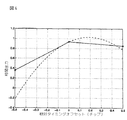
図4を参照すると、ステップ208 でのフィンガー割当て及び制御ユニット20によって実行される2次近似の例が示されている。X軸は(チップで)相対タイミングオフセットを表し、Y軸は相関出力を表す。従って、グラフはRF信号24の典型的なマルチパスのプロファイルを表している。この例は、サーチャーユニット18が1/2チップタイミング分解能を使って測定値を得るということを仮定している。御承知の通り、1/2チップタイミング分解能は最良の候補パスを測定するときにエラーを起こし、これは、おおよそ0.19チップの相対タイミングオフセットで生じた。ステップ204 で識別される最良の候補パスは、相対タイミングオフセットが0であるところに位置し、相関測定値M(0)は0.9345である。隣接する測定値は相対タイミングオフセットが+/−0.5チップのところに位置し、それぞれ、相関測定値M(−1)は0.3563であり、相関測定値M(1)は0.8540である。式(9)を適用して、t/2=0.19チップの2次式から推定タイミングオフセットを導出する。従って、この例では、ユニット20は0.19チップ、あるいはその等価な量子化値を、最大値に対応するPNオフセットへ加える。1/8チップのタイミング調整分解能を有するタイミング/制御ユニット52を持つようなフィンガー16では、0.19チップは1/8チップタイミング調整になる(すなわち1/8チップ分解能で、1/8チップ調整は0.19チップ推定値に最も近い近似といえる)。
【0045】
しかし、実際に、サーチャーユニット18によって測定されたマルチパスプロファイルの形状は、2次式では正確には表せない。例えば、非2次の形状は送信機のパルス形状のため、受信機における整合フィルタを特別に実現する必要がある。例えば、マルチパスプロファイルは、図5に示される非2次の形状を有してもよい。プロファイルがこのような非2次の形状を有するとき、2次式による推定タイミングオフセットは、十分に正確ではない。しかし、サーチャーユニットによって測定された実際のプロファイルを、実験上の測定値あるいは理論的な計算値によって推定できると仮定すると、非2次のプロファイル形状に2次近似を使うことによってもたらされる推定値エラーをアプライオリ予測(a priori predict)することができる。実際のプロファイル情報に基づいて、修正曲線を判定することができ、修正率を生成するのに修正曲線を使うことができる。これらの率は、順に、推定タイミングオフセットを修正するために2次式による推定タイミングオフセットへ適用することができる。
【0046】
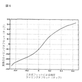
図6を参照すると、上述の2次近似によって判定された推定タイミングオフセットと、実験場の測定値あるいは理論的な計算値によって判定された実際のタイミングオフセットとの関係を示す曲線が、図5に例示される代表的な非2次の相関関数について示されている。完全な2次式の相関関数の結果、図6の曲線は、2次式フィットによる推定タイミングオフセットが、実際のタイミングオフセットに等しくなるような傾きを有する直線となるであろう。しかし、図5の相関関数が非2次の形状であるために、タイミングオフセットは、正の値へわずかにバイアスされる。タイミングオフセットの0の位置に完全に中心にあるピークに対して、図5の相関関数の2次近似では、おおよそ0.1チップの推定ピーク位置となる。図5の相関関数は、図6によって得られかつ2次式フィット方法を使って導出される推定タイミングオフセットによって指標化されるような実際の推定値でユニット20に記憶される較正テーブルまたはルックアップテーブルを作るために使うことができる。代わりの例としては、バイアスされない推定器を有する修正のテーブルを記憶することができる。
【0047】
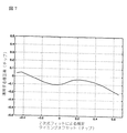
図5及び6に示された例に対して、対応する修正曲線が図7に示される。2次式による推定タイミングオフセットは、(曲線のY軸上に対する)修正率を判定するための(曲線のX軸に対する)指標として、ユニット20によって使われる。修正率は、それを単に推定タイミングオフセットに加えることによって、2次式による推定タイミングオフセットに適用される。例えば、推定ピーク位置が0である場合、実際のピーク位置を判定するために、おおよそ−0.1の修正率が推定ピーク位置に加えられる。そして修正されたタイミングオフセットは、最良の候補パスに対してフィンガー割当てを初期化するのに使われる。代わりの例としては、図7に示される修正曲線は、多項式を使ってパラメータを決めることができる。修正値は2次の修正値であるので、低い次数の多項式(例えば、3次の多項式)を使ってもよい。
【0048】
上述のように、RAKE受信機10は、最良のマルチパスのパス位置を推定することができ、サーチャーユニットを越える分解能または精度で、フィンガーユニットをこれらのマルチパスに割り当てることができる。例えば、1/2チップ分解能のサーチャーユニットで、フィンガーを1/4または1/8チップの分解能及び精度で割り当てることができる。1/4または1/8チップの分解能では、それぞれ、約0.12dBまたは0.06dBの最大SNR損失を生じるであろう。上述のようにパス位置を推定することによって、より複雑ではないハードウェア実現を有する、より低い分解能のサーチャーユニットをまだ使うことができる。
【0049】
【発明の効果】
上述のように、本発明の方法及び装置は、基地局あるいは移動局のどちらに対しても組み入れるためにCDMARAKE受信機で初期フィンガー割当てをするのに使うことができる。さらに、遅延ロックループが調整をするような速さよりも速い速さでRAKE受信機が動作する間でも、上述のやり方をフィンガータイミングを調整あるいは修正するのに使うことができる。アプリケーションを更新するために、上述のアルゴリズムは、図1の符号トラッキングループ88を取り替えるトラッキングブロック内で各フィンガー16によって実現される。このアルゴリズムは、上述の方法 (例えば同時、早期及び末期のサンプルを2次式にあてはめることによって)と同様な方法でタイミングオフセットを導出するよう、同時、早期及び末期のサンプルを処理し、導出されたタイミングオフセットをトラッキング調整信号90をフィンガーが同時信号をトラッキングするように調整するのに使う。非2次の効果をもたらすために、修正曲線またはルックアップテーブルに基づく修正率を生成して2次式から導出されたタイミングオフセットに適用することができる。それゆえ、フィンガー16のタイミングは、受信機の動作の間、同時信号をトラッキングするために直ちに調整され、符号トラッキングループ88内の遅延ロックループによって実行される比較的遅い調整を待つ必要がなくなる。上記のアルゴリズムを使うRAKE受信機の動作の間のフィンガー16の調整を、前述のアルゴリズムを初期フィンガー調整するために使うか使わないかに関わらず実行することができる。
【0050】
詳細な説明で開示されてないが本発明の範囲及び精神内に明確にあてはまるような、更なる実施例及び用途が存在することは明らかである。例えば、推定タイミングオフセットが2次等式の関数として導かれるが、適当に測定あるいはサンプルされた信号入力から推定タイミングオフセットを導出するために、他の関数あるいは公式を使ってもよい。従って本願は、限定を目的としているのではなく、本発明の範囲は添付された請求項に規定される。
【図面の簡単な説明】
【図1】サーチャーユニットと、フィンガー割当て及び制御と、重ね合せた関係で示される複数のフィンガー処理要素とを有する符号分割多元接続(CDMA)RAKE受信機のブロック図である。
【図2】図1に示されるサーチャーユニットのブロック図である。
【図3】図1に示される、サーチャーユニットを読み、フィンガー処理要素によって復調される最良の候補パスを識別し、最良の候補パスに対して高解像度のタイミングオフセットを導出して、フィンガー処理要素を最良の候補パスに割り当てるための、フィンガー割当て及び制御ユニットによって実行される典型的なフローチャートを示す図である。
【図4】フィンガー処理要素を割り当てるために使われる高解像度のタイミングオフセット(チップで)を導出するために、フィンガー割当て及び制御ユニットによって実行される2次近似を例示する一般的なグラフを示す図である。
【図5】図4に示される2次形状とは異なる相関関数の可能性のある形状を例示する一般的なグラフを示す図である。
【図6】2次近似により判定された推定タイミングオフセットと、図5に例示された非2次の相関関数に対する実際のタイミングオフセットとの関係を示す曲線を表わす図である。
【図7】実際のタイミングオフセットを生成するために、2次近似によって判定された推定タイミングオフセットに適用(すなわち付加)され得る修正率を判定するのに使われる、図5に示された非2次の相関関数に対する修正曲線を示す図である。
【符号の説明】
10…RAKE受信機
12…アンテナ
14…入力回路
16…フィンガー処理要素
18…サーチャーユニット
20…フィンガー割当て及び制御ユニット
22…合成器
24…拡散スペクトラム無線周波数(RF)信号
26,30…復調器
28…バンドパスフィルタ
32…整合フィルタ
34…キャリア周波数信号
36…IF周波数
38…同相信号成分
40…直交信号成分
42…早期サンプル回路
44…同期サンプル回路
46…末期サンプル回路
48…同時サンプル
50…サンプルタイミング信号
52…タイミング/制御ユニット
54…早期サンプリング
56…末期サンプリング
58,60…遅延要素
62…乗算器
64,66,68,70…信号処理要素
72,74,76,78…積分器
80…トラヒックチャネル同時サンプル
82…パイロットチャネル同時サンプル
84…遅延信号成分
86…早期信号成分
88…符号トラッキングループ
90…トラッキング調整信号
92…復調器ユニット
94…復調出力シンボル
96…高品質出力信号
98…測定値
100…初期フィンガー割当て信号
102…サンプル回路
104…合成逆拡散器
106…アキュムレータ
108…振幅2乗ユニット
110…信号入力[0001]
BACKGROUND OF THE INVENTION
The present invention relates generally to the field of spread spectrum communications, and more particularly to the assignment of finger processing elements in a code division multiple access (CDMA) RAKE receiver.
[0002]
[Prior art]
Code division multiple access (CDMA) is a technique for spread spectrum communication and is becoming popular in mobile wireless communication systems (eg, digital cellular radio systems). In a CDMA system, the base station transmits separate information signals simultaneously to multiple subscriber mobile stations in a single frequency band, so that the time domain and frequency domain are shared simultaneously by all users. A CDMA system has an increased spectral efficiency compared to other multiple access systems (eg, frequency division multiple access and time division multiple access) and a path diversity technique as described below. ) To reduce the effects of signal fading.
[0003]
Prior to transmission, the base station multiplexes individual information signals directed to each of the mobile stations by a unique signature sequence called a pseudo-noise (PN) sequence. This PN sequence is formed by multiplexing a long pseudo-noise with a time offset, which is used to distinguish various base stations in the network, together with a short code unique to each mobile station, such as a Walsh code. used. Multiplexing information signals with signature sequences spreads the spectrum of the signal by increasing the transmission rate from the bit rate to the chip rate. The spread spectrum signal directed to all subscriber mobile stations is transmitted simultaneously by the base station. At the time of reception, each mobile station despreads the received spread spectrum signal by multiplying the received signal by a unique signature sequence assigned to the mobile station. The result is then integrated to separate the information signal intended for a particular mobile station from other signals intended for other mobile stations. Signals directed to other mobile stations appear as noise. The structure and operation of a CDMA system is well known. For example, Andrew J. Viterbi, “CDMA Principles of Spread Spectrum Communication”, Addison-Wesley Publishing, 1995, Marvin K. Simon, Jim K. Omura, Robert A. Scholtz, and Barry K See Levitt, “Spread Spectrum Communications Handbook”, McGraw-Hill, Inc., 1994, etc.
[0004]
An advantage of a CDMA system over other multiple access telecommunications systems is that the CDMA system can take advantage of path diversity of incoming radio frequency (RF) signals. The CDMA signal is transmitted from the transmitter to the receiver via a channel having several independent paths called “multipath”. Each multipath represents a separate route through which information signals are exchanged between the transmitter and the receiver. The signal so transmitted appears at the receiver as multiple multipath signals or “multipath”. Each multipath may arrive at the receiver with any timing delay, and each multipath may have different signal strengths due to signal fading at any time.
[0005]
CDMA systems use “RAKE” receivers in mobile stations and base stations to take advantage of this path diversity. The RAKE receiver estimates the timing delay introduced by each of one or more multipaths relative to a certain reference (eg, line-of-sight delay) and has the highest signal strength. Use the estimated timing delay to receive the path. A typical RAKE receiver has multiple (eg, 3-6) RAKE branches or “finger”. Each finger is an independent receiver unit, which assembles and demodulates certain received multipaths assigned to the finger. The RAKE receiver also has a separate “searcher” that finds the various signal elements of the transmitted information signal using the receiver's assigned signature sequence, and for the various signal elements. Detect the phase. The timing of each finger is controlled to correlate with the particular multipath found by the searcher arriving at the receiver with a slightly different delay. Thus, each finger is “assigned” to a particular multipath by controlling its timing to match the arrival of the multipath. The demodulated output from each finger represents one multipath, which is then combined into a high quality output signal that combines the energy received from each demodulated multipath. To do. The implementation of a RAKE receiver is commonly known as both forward and reverse CDMA channels. For example, R. Price and PE Green, Jr, “A Communication Technique for Multipath Channel”, 46 Proc. Inst. Rad. Eng. 555-70 (March 1958), G. Cooper and See C. McGillem's “Modern Communication and Spread Spectrum”, Chapter 12, McGraw-Hill, NY, 1986.
[0006]
[Problems to be solved by the invention]
Generally, a RAKE receiver estimates a channel using a searcher having 1/2 chip resolution (ie, -0.25 / + 0.25 chip resolution), and fingers are assigned using the same resolution. The resolution of the finger assignment causes a timing misalignment between the received signal and the locally generated pseudo-noise (PN) sequence at the finger, but that finger results in a reduced signal-to-noise ratio (SNR) Or, a reduced frame error rate (FER) performance occurs. For example, with a 1/2 chip resolution for searcher and finger assignment, the resulting 0.25 chip timing misalignment results in a SNR reduction on the order of 1 dB. Receivers typically have a delay locked loop to correct such allocation errors, but the loss due to initial timing misalignment is significant in the dynamic environment faced by CDMA mobile stations, There, finger reassignment may be performed every 5-10 frames. Delay locked loops typically need to correct such initial timing misalignments on the order of 2 frames, and delay locked loops are too slow so that timing misalignment of initial finger assignment is ignored in receiver performance. It will have an effect that cannot be done.
[0007]
One way to reduce the performance issues associated with timing misalignment introduced by initial finger assignment is to use a searcher with improved resolution to estimate the channel. For example, a searcher having a 1/4 or 1/8 chip resolution can be used. However, the hardware implementation of such a high resolution searcher is more complex than the implementation of a 1/2 chip resolution searcher and is neither economical nor practical for the construction of a CDMA mobile station. Another way is to use a delay locked loop with a fast time constant directly after the initial finger assignment, but after a certain time interval a shorter time constant follows. However, the hardware implementation of such a delay locked loop is also more complex, and initial finger assignment still results in significant timing misalignment. Therefore, it would be desirable to improve not only the finger assignment update in the RAKE receiver, but also the initial finger assignment without increasing the hardware implementation complexity for the searcher or delay locked loop.
[0008]
[Means for Solving the Problems]
An advantage of the present invention is that it provides a method for determining finger assignment in a CDMA RAKE receiver that has reduced timing misalignment as compared to timing misalignment of conventional RAKE receivers. This method can improve the SNR and FER resulting from the initial finger assignment, and provides a means for tracking multipath signals for updating the finger assignment during operation.
[0009]
An advantage of the present invention is also to provide a method for determining finger assignment with a resolution higher than the resolution of the searcher.
A further advantage of the present invention provides a RAKE receiver with improved initial finger assignment such that timing misalignment is reduced.
Another further advantage of the present invention is to provide a RAKE receiver with improved capability to update finger assignments while tracking any multipath signal.
[0010]
Yet another advantage of the present invention is to provide a RAKE receiver and method that uses the improved capability of finger assignment determination that can be used at base stations and mobile stations in a CDMA communication system for this purpose. is there.
One embodiment of the present invention relates to a method for assigning finger processing elements in a RAKE receiver used in a CDMA communication system. The method includes a receiving step of receiving a spread spectrum radio frequency (RF) signal having a plurality of multipath signal components forming a multipath profile, and a measuring step of measuring the profile to obtain a series of measurement values. . Adjacent measurements in the series are separated by a predetermined timing resolution, but each measurement has an amplitude that indicates signal strength. The method also identifies the best candidate path of the RF signal to demodulate by determining which measurement in the series of measurements has the highest signal strength; A derivation step for deriving a timing offset for the best candidate path as a function of at least the measurement values for the path and adjacent measurements; and an assignment step for assigning finger processing elements to the best candidate path using the derived timing offset; Have The derived timing offset has a resolution higher than a predetermined timing resolution.
[0011]
Another embodiment of the present invention relates to a method for assigning finger processing elements in a RAKE receiver used in a CDMA communication system. The method includes a receiving step of receiving a spread spectrum radio frequency (RF) signal having a plurality of multipath signal components forming a multipath profile, and a measuring step of measuring the profile to obtain a series of measurement values. . Adjacent measurements in the series are separated by a predetermined timing resolution, but each measurement has an amplitude that indicates signal strength. The method also includes an identifying step that identifies the best candidate path of the RF signal to demodulate by determining which measurement in the series of measurements has the highest signal strength, and a finger processing element includes And a determination step for determining whether it can be used. If available, the timing offset is derived for the best candidate path, at least as a function of the measurements for the path and the adjacent measurements. The derived timing offset is then used to assign available finger processing elements to the best candidate path. The resolution of the derived timing offset is higher than the predetermined timing resolution.
[0012]
Yet another embodiment of the present invention relates to a RAKE receiver for use in a CDMA communication system. The RAKE receiver has an antenna for receiving a spread spectrum radio frequency (RF) signal having multipath components that form a multipath profile, and a finger processing element coupled to the antenna. Each finger processing element can be assigned to a specific propagation path of the RF signal and can demodulate the assigned path to produce a demodulated signal. A searcher unit coupled to the antenna measures the multipath profile of the RF signal to obtain a series of measurements. The searcher unit has a predetermined timing resolution that separates adjacent measurements in the sequence, but each measurement has an amplitude that indicates the signal strength. A finger assignment and control unit coupled to the searcher unit and the finger processing element is for reading a sequence of measurements and demodulating by determining which measurement in the sequence has the highest signal strength. Identifying the best candidate paths of the RF signal, deriving timing offsets for the best candidate paths as a function of at least these paths and their adjacent measurements, and using at least the derived timing offsets for finger processing elements Is assigned to the best candidate path. The derived timing offset has a higher resolution than the predetermined timing resolution of the searcher unit. A combiner combines the demodulated signals from each of the finger processing elements and generates an output signal from the RAKE receiver.
[0013]
Another embodiment of the present invention relates to a method for adjusting a finger processing element of a RAKE receiver for use in a CDMA communication system. The method includes a receiving step of receiving a spread spectrum radio frequency (RF) signal having a plurality of multipath signal components forming a multipath profile. One of the multipath signal elements of the spread spectrum RF signal is sampled to obtain early, simultaneous and late samples using finger processing elements, and the timing offset is at least early of the sampled multipath signal component, Derived for simultaneous samples as a function of simultaneous and late samples. The finger processing element uses the derived timing offset to adjust to track the timing of simultaneous samples of the sampled multipath signal component.
[0014]
DETAILED DESCRIPTION OF THE INVENTION
An understanding of the present invention is facilitated by considering the following detailed description of a preferred embodiment of the invention with reference to the accompanying drawings.
A CDMA RAKE receiver for use in a code division multiple access (CDMA) communication system is shown in FIG. The RAKE receiver has an antenna element 12, an input circuit 14, a plurality of finger processing elements or “fingers” 16, a searcher unit or “searcher” 18, a finger assignment and
[0015]
The antenna element 12 receives a spread spectrum radio frequency (RF) signal 24 transmitted by one or more CDMA base stations (not shown). Input circuit 14 receives RF signal 24 from antenna element 12 and processes it using
[0016]
Each
[0017]
Each
[0018]
Each
Each
[0019]
The filtering performed by
[0020]
[Equation 5]
Where m (k) is the kth symbol and aI nIs an in-phase PN series, aQ nIs an orthogonal PN sequence and TCIs the chip period, f is the carrier frequency, φ is the unknown phase, and h (t) is the bandpass filter impulse response of the transmitter. The term m (k) is the chip NCAnd is known for the pilot channel, but not for the traffic channel.
[0022]
Referring to FIG. 2, the
[0023]
[Formula 6]
[0025]
[Expression 7]
![]()
Here, h ′ (t) is an impulse response of the matched
[0027]
[Equation 8]
![]()
Where delay is a small delay of the PN timing generated by the combined
[0029]
Referring briefly to FIG. 1 again, the
[0030]
Referring to the flowchart of FIG. 3, the processing steps performed by finger assignment and
[0031]
In
[0032]
In
[0033]
[Equation 9]
![]()
Can be approximated by The unknown coefficients A, B and C are solutions for this linear system.
[0035]
[Expression 10]
![]()
## EQU11 ##
[Expression 12]
![]()
The quadratic peak corresponds to a multipath with peak signal strength and is obtained by time differentiation with a profile in which Y is equal to zero.
[0039]
[Formula 13]
When equations (5) to (8) are combined and solved for t, the following is obtained.
[0041]
[Expression 14]
The peak timing offset is estimated based on a second order approximation as t / f, where 1 / f is the measured value sampling period (eg, timing offset = 1/2 for a 1/2 chip searcher) Is defined as the fraction of the chip corresponding to. This estimated timing offset is used by
[0043]
This parabolic or quadratic approximation may be implemented in a digital signal processing (DSP) integrated circuit, whether floating or fixed. As an alternative example, because the computational load is relatively low, the process can also be implemented with a microcontroller (MCU) or other hardware circuit capable of performing the process shown in FIG.
The
[0044]
Referring to FIG. 4, an example of a quadratic approximation performed by finger assignment and
[0045]
However, in practice, the shape of the multipath profile measured by the
[0046]
Referring to FIG. 6, a curve showing the relationship between the estimated timing offset determined by the above-mentioned second order approximation and the actual timing offset determined by the measured value of the experimental field or the theoretical calculated value is shown in FIG. A representative non-second order correlation function is illustrated. As a result of the complete quadratic correlation function, the curve of FIG. 6 will be a straight line with a slope such that the estimated timing offset due to the quadratic fit is equal to the actual timing offset. However, the timing offset is slightly biased to a positive value due to the non-quadratic shape of the correlation function of FIG. With respect to the peak that is completely centered at the zero position of the timing offset, the second order approximation of the correlation function in FIG. 5 has an estimated peak position of approximately 0.1 chip. The correlation function of FIG. 5 is a calibration table or lookup stored in
[0047]
For the example shown in FIGS. 5 and 6, the corresponding correction curve is shown in FIG. The quadratic estimated timing offset is used by
[0048]
As described above, the
[0049]
【The invention's effect】
As described above, the method and apparatus of the present invention can be used to make initial finger assignments at a CDMA RAKE receiver for incorporation into either a base station or a mobile station. In addition, the above approach can be used to adjust or modify finger timing while the RAKE receiver is operating at a rate faster than the delay lock loop can adjust. In order to update the application, the algorithm described above is implemented by each
[0050]
It will be apparent that there are additional embodiments and applications which are not disclosed in the detailed description but which clearly fall within the scope and spirit of the invention. For example, the estimated timing offset is derived as a function of a quadratic equation, but other functions or formulas may be used to derive the estimated timing offset from appropriately measured or sampled signal inputs. Accordingly, this application is not intended to be limiting, but the scope of the present invention is defined in the appended claims.
[Brief description of the drawings]
FIG. 1 is a block diagram of a code division multiple access (CDMA) RAKE receiver having a searcher unit, finger assignment and control, and a plurality of finger processing elements shown in a superimposed relationship.
FIG. 2 is a block diagram of a searcher unit shown in FIG.
3 reads the searcher unit shown in FIG. 1, identifies the best candidate path demodulated by the finger processing element, derives a high-resolution timing offset for the best candidate path, FIG. 6 shows an exemplary flowchart executed by the finger assignment and control unit for assigning to the best candidate path.
FIG. 4 is a general graph illustrating a quadratic approximation performed by a finger assignment and control unit to derive a high resolution timing offset (in chips) used to assign finger processing elements. It is.
FIG. 5 is a diagram illustrating a general graph illustrating a possible shape of a correlation function different from the quadratic shape shown in FIG.
6 is a diagram illustrating a curve indicating a relationship between an estimated timing offset determined by second-order approximation and an actual timing offset with respect to the non-second-order correlation function illustrated in FIG.
7 is a non-2 shown in FIG. 5 used to determine a correction factor that can be applied (ie, added) to the estimated timing offset determined by the quadratic approximation to generate an actual timing offset. It is a figure which shows the correction curve with respect to the following correlation function.
[Explanation of symbols]
10 ... RAKE receiver
12 ... Antenna
14 ... Input circuit
16: Finger processing element
18 ... Searcher unit
20 ... Finger assignment and control unit
22 Synthesizer
24. Spread spectrum radio frequency (RF) signal
26, 30 ... demodulator
28 ... Band pass filter
32 ... Matched filter
34 ... Carrier frequency signal
36 ... IF frequency
38 ... In-phase signal component
40: Orthogonal signal component
42 ... Early sample circuit
44 ... Synchronous sampling circuit
46 ... Terminal sample circuit
48 ... Simultaneous sample
50 ... Sample timing signal
52. Timing / control unit
54 ... Early sampling
56 ... Terminal sampling
58, 60 ... delay element
62 ... Multiplier
64, 66, 68, 70 ... signal processing elements
72, 74, 76, 78 ... integrator
80 ... Simultaneous traffic channel samples
82 ... Simultaneous pilot channel samples
84 ... Delayed signal component
86 ... Early signal component
88 ... code tracking loop
90 ... Tracking adjustment signal
92. Demodulator unit
94: Demodulated output symbol
96 ... High quality output signal
98 ... Measured value
100: Initial finger assignment signal
102 ... Sample circuit
104 ... Synthetic despreader
106 ... Accumulator
108 ... square unit of amplitude
110 ... Signal input
Claims (30)
マルチパスプロファイルを形成する複数のマルチパス信号成分を有する拡散スペクトラム無線周波数(RF)信号を受信する受信ステップと、
前記マルチパスプロファイルを測定して測定値の系列を獲得する測定ステップであって、前記系列内の隣接する測定値は、所定のタイミング分解能によって分離され、前記各測定値は信号強度を示す振幅を有するような測定ステップと、
前記測定値の系列内のどの測定値が最高の信号強度を有するかを判定することによって、復調するための前記RF信号の最良の候補パスを識別する識別ステップと、
少なくとも前記最良の候補パスに対する測定値及びそれに隣接する測定値の関数として、前記最良の候補パスに対するタイミングオフセットを導出する導出ステップであって、前記導出されたタイミングオフセットは、前記所定のタイミング分解能よりも高い分解能を有するような導出ステップと、
前記導出されたタイミングオフセットを使って、前記最良の候補パスに前記RAKE受信機のフィンガー処理要素を割り当てる割当てステップとを備えることを特徴とするRAKE受信機におけるフィンガー処理要素の割当て方法。A method for assigning finger processing elements in a RAKE receiver for use in a CDMA communication system, comprising:
Receiving a spread spectrum radio frequency (RF) signal having a plurality of multipath signal components forming a multipath profile;
A measurement step of measuring the multipath profile to obtain a series of measurement values, wherein adjacent measurement values in the series are separated by a predetermined timing resolution, and each measurement value has an amplitude indicating a signal strength. Measuring steps such as having
Identifying the best candidate path of the RF signal to demodulate by determining which measurement in the series of measurements has the highest signal strength;
A derivation step of deriving a timing offset for the best candidate path as a function of at least a measurement value for the best candidate path and a measurement value adjacent thereto, wherein the derived timing offset is obtained from the predetermined timing resolution; A derivation step that also has a high resolution,
Allocating a finger processing element of the RAKE receiver to the best candidate path using the derived timing offset; and assigning a finger processing element in the RAKE receiver.
マルチパスプロファイルを形成する複数のマルチパス信号成分を有する拡散スペクトラム無線周波数(RF)信号を受信する受信ステップと、
前記マルチパスプロファイルを測定して測定値の系列を獲得する測定ステップであって、前記系列内の隣接する測定値は、所定のタイミング分解能によって分離され、前記各測定値は信号強度を示す振幅を有するような測定ステップと、
前記測定値の系列内のどの測定値が最高の信号強度を有するかを判定することによって、復調するための前記RF信号の最良の候補パスを識別する識別ステップと、
フィンガー処理要素が利用可能であるかを判定し、もしそうであるならば、少なくとも前記最良の候補パスに対する測定値及びそれに隣接する測定値の関数として、前記最良の候補パスに対するタイミングオフセットを導出するが、前記導出されたタイミングオフセットの分解能は、前記所定のタイミング分解能よりも高く、そして、前記導出されたタイミングオフセットを使って、前記最良の候補パスに前記利用可能なフィンガー処理要素を割り当てる判定ステップとを備えることを特徴とするRAKE受信機におけるフィンガー処理要素の割当て方法。A method for assigning finger processing elements in a RAKE receiver for use in a CDMA communication system, comprising:
Receiving a spread spectrum radio frequency (RF) signal having a plurality of multipath signal components forming a multipath profile;
A measurement step of measuring the multipath profile to obtain a series of measurement values, wherein adjacent measurement values in the series are separated by a predetermined timing resolution, and each measurement value has an amplitude indicating a signal strength. Measuring steps such as having
Identifying the best candidate path of the RF signal to demodulate by determining which measurement in the series of measurements has the highest signal strength;
Determine if a fingering element is available, and if so, derive a timing offset for the best candidate path as a function of at least the measurements for the best candidate path and the adjacent measurements But the resolution of the derived timing offset is higher than the predetermined timing resolution, and using the derived timing offset to assign the available finger processing element to the best candidate path A method for assigning finger processing elements in a RAKE receiver.
マルチパスプロファイルを形成する複数のマルチパス成分を有する拡散スペクトラム無線周波数(RF)信号を受信するためのアンテナと、
該アンテナに結合された複数のフィンガー処理要素であって、該各フィンガー処理要素は、前記RF信号の特定の伝搬パスに割当てられ、かつ前記RF信号の割り当てられた伝搬パスを復調して復調された信号を生成するように構成されるフィンガー処理要素と、
前記アンテナに結合され、前記RF信号の前記マルチパスプロファイルを測定して測定値の系列を獲得するよう構成されるサーチャーユニットであって、該サーチャーユニットは、前記測定値の系列内で隣接する測定値を分離する所定のタイミング分解能を有し、前記各測定値は信号強度を示す振幅を有するようなサーチャーユニットと、
前記サーチャーユニットと前記複数のフィンガー処理要素とに結合されるフィンガー割当て及び制御ユニットであって、前記測定値の系列を読み込んで、少なくとも前記最良の候補パスの前記測定値及びそれに隣接する前記測定値の関数として、前記最良の候補パスに対して、前記サーチャーユニットの前記所定のタイミング分解能よりも高い分解能を有するようなタイミングオフセットを導出し、少なくとも前記導出されたタイミングオフセットを使って、前記フィンガー処理要素を前記最良の候補パスに割り当てるように構成されるフィンガー割当て及び制御ユニットと、
前記複数のフィンガー処理要素に結合され、前記フィンガー処理要素のそれぞれから前記復調された信号を合成して前記RAKE受信機からの出力信号を生成するよう構成される合成器とを備えることを特徴とするRAKE受信機。A RAKE receiver for use in a CDMA communication system,
An antenna for receiving a spread spectrum radio frequency (RF) signal having a plurality of multipath components forming a multipath profile;
A plurality of finger processing elements coupled to the antenna, each finger processing element being assigned to a specific propagation path of the RF signal and demodulating and demodulating the assigned propagation path of the RF signal; A finger processing element configured to generate a processed signal;
A searcher unit coupled to the antenna and configured to measure the multipath profile of the RF signal to obtain a sequence of measurements, the searcher unit comprising adjacent measurements in the sequence of measurements A searcher unit having a predetermined timing resolution for separating values, wherein each measured value has an amplitude indicative of signal strength;
A finger assignment and control unit coupled to the searcher unit and the plurality of finger processing elements, wherein the measurement value series is read and at least the measurement value of the best candidate path and the measurement value adjacent thereto For the best candidate path, deriving a timing offset having a resolution higher than the predetermined timing resolution of the searcher unit, and using at least the derived timing offset, the finger processing A finger assignment and control unit configured to assign an element to the best candidate path;
A combiner coupled to the plurality of finger processing elements and configured to combine the demodulated signals from each of the finger processing elements to generate an output signal from the RAKE receiver. RAKE receiver.
マルチパスプロファイルを形成する複数のマルチパス信号成分を有する拡散スペクトラム無線周波数(RF)信号を受信する受信ステップと、
フィンガー処理要素を使って早期、同時及び末期のサンプルを獲得するために前記拡散スペクトラムRF信号の前記マルチパス信号成分の1つをサンプルするサンプルステップと、
少なくとも前記サンプルされたマルチパス信号成分の前記早期、同時及び末期のサンプルの関数として、前記同時サンプルに対するタイミングオフセットを導出する導出ステップと、
前記導出されたタイミングオフセットを使って前記サンプルされたマルチパス信号成分の前記同時サンプルのタイミングをトラッキングするよう前記フィンガー処理要素を調整する調整ステップとを備えることを特徴とするRAKE受信機におけるフィンガー処理要素の調整方法。A method for adjusting a finger processing element in a RAKE receiver used in a CDMA communication system, comprising:
Receiving a spread spectrum radio frequency (RF) signal having a plurality of multipath signal components forming a multipath profile;
A sample step of sampling one of the multipath signal components of the spread spectrum RF signal to obtain early, simultaneous and late samples using finger processing elements;
Deriving to derive a timing offset for the simultaneous samples as a function of at least the early, simultaneous and late samples of the sampled multipath signal component;
Finger processing in a RAKE receiver comprising adjusting the finger processing element to track the timing of the simultaneous samples of the sampled multipath signal component using the derived timing offset How to adjust the element.
Applications Claiming Priority (2)
| Application Number | Priority Date | Filing Date | Title |
|---|---|---|---|
| US09/012953 | 1998-01-26 | ||
| US09/012,953 US6269075B1 (en) | 1998-01-26 | 1998-01-26 | Finger assignment in a CDMA rake receiver |
Publications (3)
| Publication Number | Publication Date |
|---|---|
| JPH11261528A JPH11261528A (en) | 1999-09-24 |
| JPH11261528A5 JPH11261528A5 (en) | 2005-03-03 |
| JP3961703B2 true JP3961703B2 (en) | 2007-08-22 |
Family
ID=21757546
Family Applications (1)
| Application Number | Title | Priority Date | Filing Date |
|---|---|---|---|
| JP01680399A Expired - Fee Related JP3961703B2 (en) | 1998-01-26 | 1999-01-26 | RAKE receiver and method for assigning and adjusting finger processing elements in RAKE receiver |
Country Status (4)
| Country | Link |
|---|---|
| US (1) | US6269075B1 (en) |
| EP (1) | EP0932263A3 (en) |
| JP (1) | JP3961703B2 (en) |
| KR (1) | KR19990067991A (en) |
Families Citing this family (122)
| Publication number | Priority date | Publication date | Assignee | Title |
|---|---|---|---|---|
| JP3694396B2 (en) * | 1997-10-20 | 2005-09-14 | 松下電器産業株式会社 | Wireless communication apparatus and wireless communication method |
| US7496072B2 (en) | 1997-12-17 | 2009-02-24 | Interdigital Technology Corporation | System and method for controlling signal strength over a reverse link of a CDMA wireless communication system |
| US7394791B2 (en) * | 1997-12-17 | 2008-07-01 | Interdigital Technology Corporation | Multi-detection of heartbeat to reduce error probability |
| US9525923B2 (en) | 1997-12-17 | 2016-12-20 | Intel Corporation | Multi-detection of heartbeat to reduce error probability |
| US7936728B2 (en) | 1997-12-17 | 2011-05-03 | Tantivy Communications, Inc. | System and method for maintaining timing of synchronization messages over a reverse link of a CDMA wireless communication system |
| US6222832B1 (en) * | 1998-06-01 | 2001-04-24 | Tantivy Communications, Inc. | Fast Acquisition of traffic channels for a highly variable data rate reverse link of a CDMA wireless communication system |
| US7079523B2 (en) * | 2000-02-07 | 2006-07-18 | Ipr Licensing, Inc. | Maintenance link using active/standby request channels |
| US8175120B2 (en) | 2000-02-07 | 2012-05-08 | Ipr Licensing, Inc. | Minimal maintenance link to support synchronization |
| KR100269341B1 (en) * | 1997-12-19 | 2000-10-16 | 서평원 | Baseband signal demodulation apparatus and method in mobile communication system |
| JP3600037B2 (en) * | 1998-02-02 | 2004-12-08 | 株式会社リコー | Correlation peak detection circuit |
| JP2937994B1 (en) * | 1998-03-04 | 1999-08-23 | 日本電気移動通信株式会社 | Cellular system, mobile portable device, base station device, and optimal path detection method and device |
| JPH11261440A (en) * | 1998-03-11 | 1999-09-24 | Oki Electric Ind Co Ltd | Receiver |
| US6421334B1 (en) * | 1998-05-13 | 2002-07-16 | Nortel Networks Limited | Technique for time alignment of uplink CDMA signals |
| US7221664B2 (en) * | 1998-06-01 | 2007-05-22 | Interdigital Technology Corporation | Transmittal of heartbeat signal at a lower level than heartbeat request |
| US8134980B2 (en) | 1998-06-01 | 2012-03-13 | Ipr Licensing, Inc. | Transmittal of heartbeat signal at a lower level than heartbeat request |
| US7773566B2 (en) | 1998-06-01 | 2010-08-10 | Tantivy Communications, Inc. | System and method for maintaining timing of synchronization messages over a reverse link of a CDMA wireless communication system |
| JP3031349B2 (en) * | 1998-09-02 | 2000-04-10 | 日本電気株式会社 | CDMA signal receiver |
| KR100407523B1 (en) * | 1998-10-27 | 2003-11-28 | 지멘스 악티엔게젤샤프트 | Method for controlling memory access in rake receivers with early-late tracking in telecommunications systems operated by wireless telecommunication between mobile and/or stationary transmitters/receivers, especially in third-generation mobile radio systems |
| JP3458841B2 (en) * | 1998-11-19 | 2003-10-20 | 三菱電機株式会社 | Receiver and demodulator applied to mobile communication system |
| US7184462B1 (en) * | 1998-12-04 | 2007-02-27 | Telefonaktiebolaget L M Ericsson (Publ) | Method and apparatus for configuring a rake receiver |
| GB2391141B (en) * | 1998-12-10 | 2004-04-28 | Nec Corp | CDMA reception apparatus and power control method therefor |
| JP3264259B2 (en) | 1998-12-10 | 2002-03-11 | 日本電気株式会社 | CDMA receiver |
| US6965778B1 (en) * | 1999-04-08 | 2005-11-15 | Ipr Licensing, Inc. | Maintenance of channel usage in a wireless communication system |
| US6314130B1 (en) * | 1999-04-28 | 2001-11-06 | Dspc Technologies, Ltd. | System and method for joint time tracking of multiple paths |
| US7031271B1 (en) * | 1999-05-19 | 2006-04-18 | Motorola, Inc. | Method of and apparatus for activating a spread-spectrum radiotelephone |
| JP3369513B2 (en) * | 1999-07-02 | 2003-01-20 | 松下電器産業株式会社 | Communication terminal device and wireless reception method |
| EP1089452A1 (en) * | 1999-09-28 | 2001-04-04 | Lucent Technologies Inc. | Fractional sample timing error estimation for W-CDMA |
| US6798737B1 (en) * | 1999-10-06 | 2004-09-28 | Texas Instruments Incorporated | Use of Walsh-Hadamard transform for forward link multiuser detection in CDMA systems |
| US6483867B1 (en) * | 1999-11-22 | 2002-11-19 | Nokia Mobile Phones Ltd. | Tracking loop realization with adaptive filters |
| JP3566608B2 (en) * | 1999-12-28 | 2004-09-15 | Necエレクトロニクス株式会社 | Semiconductor integrated circuit |
| EP1117185A1 (en) * | 2000-01-14 | 2001-07-18 | Lucent Technologies Inc. | Method and rake receiver for code-tracking in CDMA communication systems |
| EP1117186A1 (en) * | 2000-01-14 | 2001-07-18 | Lucent Technologies Inc. | Adaptive code-tracking RAKE receiver for direct-sequence code-division multiple access (cdma) communications |
| US7184457B2 (en) * | 2000-02-28 | 2007-02-27 | Texas Instruments Incorporated | Spread spectrum path estimation |
| EP1130792A1 (en) * | 2000-03-03 | 2001-09-05 | Lucent Technologies Inc. | A method and rake receiver for phasor estimation in communication systems |
| FI20000700A7 (en) * | 2000-03-24 | 2001-09-25 | Nokia Corp | Mobile station with improved power saving and method for saving power |
| JP2001285129A (en) | 2000-03-29 | 2001-10-12 | Nec Corp | Circuit and method for cdma demodulation |
| GB0007750D0 (en) * | 2000-03-30 | 2000-05-17 | Ubinetics Ltd | A rake receiver and a method of operating a rake receiver |
| ATE403166T1 (en) * | 2000-06-06 | 2008-08-15 | Altratek Inc | SENSOR SYSTEM AND METHOD FOR DETECTING AND TRACKING TARGETS |
| US6647077B1 (en) * | 2000-07-31 | 2003-11-11 | Rf Micro Devices, Inc. | Multipath parameter estimation in spread-spectrum communications systems |
| US6728324B1 (en) | 2000-07-31 | 2004-04-27 | Rf Micro Devices, Inc. | Method and apparatus for multipath signal compensation in spread-spectrum communications systems |
| US7031373B1 (en) * | 2000-08-15 | 2006-04-18 | Motorola, Inc. | Apparatus for controlling a plurality of receiver fingers in a CDMA receiver |
| GB0022634D0 (en) * | 2000-09-15 | 2000-11-01 | Koninkl Philips Electronics Nv | Secondary station and method of operating the station |
| US6600777B1 (en) * | 2000-09-29 | 2003-07-29 | Qualcomm, Incorporated | Assignment and deassignment of CDMA second finger |
| US7613229B1 (en) * | 2000-10-02 | 2009-11-03 | St Wireless Sa | Method and apparatus for combined finger management and finger lock for a multipath signals in a wireless communication system |
| US6697629B1 (en) | 2000-10-11 | 2004-02-24 | Qualcomm, Incorporated | Method and apparatus for measuring timing of signals received from multiple base stations in a CDMA communication system |
| FI113921B (en) * | 2000-10-30 | 2004-06-30 | Nokia Corp | Receiver, Receiving Method, Computer Program, and Computer Memory |
| JP2002164811A (en) * | 2000-11-24 | 2002-06-07 | Toshiba Corp | Timing identification method, timing identification device, and timing identification system |
| US8155096B1 (en) | 2000-12-01 | 2012-04-10 | Ipr Licensing Inc. | Antenna control system and method |
| CN1141815C (en) * | 2000-12-18 | 2004-03-10 | 信息产业部电信传输研究所 | A frequency automatic correction device for code division multiple access multipath fading channel |
| US6771692B2 (en) * | 2001-01-11 | 2004-08-03 | Qualcomm Incorporated | Time tracking in a non-negligible multipath spacing environment |
| US6731676B2 (en) * | 2001-01-11 | 2004-05-04 | Qualcomm Inc | Assigning clusters of demodulation elements in a spread spectrum system |
| US6954448B2 (en) | 2001-02-01 | 2005-10-11 | Ipr Licensing, Inc. | Alternate channel for carrying selected message types |
| US7551663B1 (en) | 2001-02-01 | 2009-06-23 | Ipr Licensing, Inc. | Use of correlation combination to achieve channel detection |
| US7400668B2 (en) * | 2001-03-22 | 2008-07-15 | Qst Holdings, Llc | Method and system for implementing a system acquisition function for use with a communication device |
| JP3412622B2 (en) | 2001-04-18 | 2003-06-03 | 日本電気株式会社 | CDMA receiver and path protection processing method |
| DE10123333A1 (en) * | 2001-05-14 | 2002-11-28 | Infineon Technologies Ag | Method of multi-user detection using RAKE receiver structure, deactivates one or more RAKE fingers to reduce power consumption during operation |
| FI111300B (en) * | 2001-05-25 | 2003-06-30 | Nokia Corp | A method of controlling the operation of a positioning receiver and an electronic device |
| ES2624979T3 (en) | 2001-06-13 | 2017-07-18 | Intel Corporation | Apparatus for transmitting a heartbeat signal at a lower level than the heartbeat request |
| JP3866535B2 (en) * | 2001-06-26 | 2007-01-10 | 株式会社東芝 | Code division multiplexing communication apparatus and transmission path correction timing control method thereof |
| JP2003023371A (en) | 2001-07-06 | 2003-01-24 | Nec Corp | Cdma receiver, receiving method and program therefor |
| US6819931B2 (en) * | 2001-07-12 | 2004-11-16 | Qualcomm Incorporated | Method and apparatus for assigning tracking elements to received signals |
| JP4644988B2 (en) * | 2001-07-23 | 2011-03-09 | ソニー株式会社 | Wireless impulse transmitter, receiver and method |
| US7200162B2 (en) * | 2001-08-31 | 2007-04-03 | Qualcomm, Incorporated | Interpolation of channel search results |
| US7158559B2 (en) | 2002-01-15 | 2007-01-02 | Tensor Comm, Inc. | Serial cancellation receiver design for a coded signal processing engine |
| US8085889B1 (en) | 2005-04-11 | 2011-12-27 | Rambus Inc. | Methods for managing alignment and latency in interference cancellation |
| US7020180B2 (en) * | 2001-10-04 | 2006-03-28 | Qualcomm Inc. | Method and apparatus for acquiring pilots over code space and frequency errors in a CDMA communication system |
| US6584331B2 (en) | 2001-10-09 | 2003-06-24 | Nokia Corporation | Use of received signal strength indicator (RSSI) and global positioning system (GPS) to reduce power consumption in mobile station |
| WO2005081438A1 (en) * | 2001-11-19 | 2005-09-01 | Tensorcomm, Incorporated | Interference cancellation in a signal |
| US6771693B2 (en) | 2001-12-27 | 2004-08-03 | Interdigital Technology Corporation | Enhanced rake structure |
| TWI236245B (en) * | 2002-03-07 | 2005-07-11 | Benq Corp | Method of tracking finger assignment |
| US6987795B1 (en) * | 2002-04-08 | 2006-01-17 | Meshnetworks, Inc. | System and method for selecting spreading codes based on multipath delay profile estimation for wireless transceivers in a communication network |
| US7154872B2 (en) * | 2002-04-26 | 2006-12-26 | Lucent Technologies Inc. | Method and system for tracking and correcting timing errors in communication systems |
| US6967989B2 (en) * | 2002-05-17 | 2005-11-22 | Motorola, Inc. | Method and apparatus for time-sharing a rake receiver structure |
| US6795452B2 (en) | 2002-05-31 | 2004-09-21 | Sandbridge Technologies, Inc. | Method of tracking time intervals for a communication signal |
| US7801085B1 (en) * | 2002-06-03 | 2010-09-21 | Ericsson Ab | System and method of processing CDMA signals |
| US7054126B2 (en) * | 2002-06-05 | 2006-05-30 | Meshnetworks, Inc. | System and method for improving the accuracy of time of arrival measurements in a wireless ad-hoc communications network |
| US6687259B2 (en) * | 2002-06-05 | 2004-02-03 | Meshnetworks, Inc. | ARQ MAC for ad-hoc communication networks and a method for using the same |
| US7061967B2 (en) * | 2002-06-24 | 2006-06-13 | Comsys Communication & Signal Processing Ltd. | Multipath channel tap delay estimation in a CDMA spread spectrum receiver |
| US7061971B2 (en) * | 2002-07-11 | 2006-06-13 | Qualcomm Incorporated | Method and apparatus for diversity searching and demodulator assignment in a wireless communication system |
| US7340017B1 (en) * | 2002-07-30 | 2008-03-04 | National Semiconductor Corporation | System and method for finger management in a rake receiver |
| US6873826B2 (en) * | 2002-08-06 | 2005-03-29 | Motorola, Inc. | Method and mobile station for reporting multi-path signals based on minimum separation |
| US7054396B2 (en) | 2002-08-20 | 2006-05-30 | Rf Micro Devices, Inc. | Method and apparatus for multipath signal compensation in spread-spectrum communications systems |
| US7221701B2 (en) * | 2002-08-28 | 2007-05-22 | Altratek, Inc. | System and method for CDMA communications |
| US7787572B2 (en) | 2005-04-07 | 2010-08-31 | Rambus Inc. | Advanced signal processors for interference cancellation in baseband receivers |
| US7876810B2 (en) | 2005-04-07 | 2011-01-25 | Rambus Inc. | Soft weighted interference cancellation for CDMA systems |
| US7808937B2 (en) | 2005-04-07 | 2010-10-05 | Rambus, Inc. | Variable interference cancellation technology for CDMA systems |
| KR100464037B1 (en) * | 2002-10-10 | 2005-01-03 | 엘지전자 주식회사 | Finger allocation method of mobile communication system |
| WO2004047326A1 (en) * | 2002-11-15 | 2004-06-03 | Telecom Italia S.P.A. | Method and device for fine synchronization of a digital telecommunication receiver |
| US7356074B2 (en) * | 2003-05-08 | 2008-04-08 | Rf Micro Devices, Inc. | Estimation of multipath channel with sub-chip resolution |
| JP4116925B2 (en) | 2003-05-13 | 2008-07-09 | 松下電器産業株式会社 | Radio base station apparatus, control station apparatus, communication terminal apparatus, transmission signal generation method, reception method, and radio communication system |
| KR101058717B1 (en) * | 2003-05-23 | 2011-08-22 | 삼성전자주식회사 | Rake receiver and its control method in mobile communication system |
| KR100547737B1 (en) * | 2003-06-10 | 2006-01-31 | 삼성전자주식회사 | Rake receiver and method in direct sequence code division multiple access mobile communication system |
| GB2403104B (en) * | 2003-06-16 | 2006-06-14 | Inmarsat Ltd | Communication method and apparatus |
| US8391322B2 (en) * | 2003-07-09 | 2013-03-05 | Broadcom Corporation | Method and system for single weight (SW) antenna system for spatial multiplexing (SM) MIMO system for WCDMA/HSDPA |
| US7469024B2 (en) | 2003-09-02 | 2008-12-23 | Telefonaktiebolaget Lm Ericsson (Publ) | Method and apparatus for finger placement in rake receiver |
| US7233806B2 (en) * | 2003-09-30 | 2007-06-19 | Nokia Corporation | Apparatus and method employing time-multiplexed searcher finger monitoring for active set and other base stations |
| US7437135B2 (en) | 2003-10-30 | 2008-10-14 | Interdigital Technology Corporation | Joint channel equalizer interference canceller advanced receiver |
| US7756191B2 (en) * | 2003-12-22 | 2010-07-13 | Nokia Corporation | Deconvolution searcher for wireless communication system |
| US7461313B2 (en) * | 2003-12-30 | 2008-12-02 | Qualcomm Incorporated | Test pattern generation |
| US7400692B2 (en) | 2004-01-14 | 2008-07-15 | Interdigital Technology Corporation | Telescoping window based equalization |
| KR101133398B1 (en) * | 2004-04-08 | 2012-04-09 | 로카타 코퍼레이션 | Staccato pulse edge correlation |
| US7924909B2 (en) | 2004-06-02 | 2011-04-12 | Telefonaktiebolaget Lm Ericsson (Publ) | Method and apparatus for interference cancellation in wireless receivers |
| FR2871312B1 (en) * | 2004-06-03 | 2006-08-11 | St Microelectronics Sa | CHARGE MODULATION IN AN ELECTROMAGNETIC TRANSPONDER |
| US7058117B1 (en) * | 2004-07-26 | 2006-06-06 | Sandbridge Technologies, Inc. | Rake receiver with multi-path interference accommodation |
| US7403557B2 (en) * | 2004-07-27 | 2008-07-22 | Nokia Corporation | Apparatus and method for hybrid traffic and pilot signal quality determination of finger lock status of rake receiver correlators |
| US7643839B2 (en) * | 2004-10-06 | 2010-01-05 | Broadcom Corporation | Method and system for diversity processing |
| US7715806B2 (en) * | 2004-10-06 | 2010-05-11 | Broadcom Corporation | Method and system for diversity processing including using dedicated pilot method for closed loop |
| US8406251B2 (en) * | 2004-10-06 | 2013-03-26 | Broadcom Corporation | Method and system for processing multipath clusters |
| US7372895B2 (en) * | 2004-12-08 | 2008-05-13 | Telefonaktiebolaget Lm Ericsson (Publ) | Method of and system for delay estimation with minimized finger allocation |
| US8428001B2 (en) * | 2005-03-10 | 2013-04-23 | Qualcomm Incorporated | Timing corrections in a multi carrier system and propagation to a channel estimation time filter |
| US7515876B2 (en) * | 2005-05-03 | 2009-04-07 | Agere Systems Inc. | Rake receiver with time-shared fingers |
| US20070019585A1 (en) * | 2005-07-22 | 2007-01-25 | Industrial Technology Research Institute | Apparatus for path selection and signal processing in wireless communications system |
| US20070021086A1 (en) * | 2005-07-22 | 2007-01-25 | Industrial Technology Research Institute | Method for path selection and signal processing in wireless communications system |
| CN101167287B (en) * | 2005-10-11 | 2011-05-18 | 中兴通讯股份有限公司 | A mixed-path processing method in CDMA system |
| US7693241B2 (en) * | 2005-10-31 | 2010-04-06 | Qualcomm Incorporated | Rake receiver finger assignment based on signal path concentration |
| US7489904B2 (en) * | 2005-12-13 | 2009-02-10 | Motorola, Inc. | Method and system for determining the time of arrival of a direct radio signal |
| WO2008094701A1 (en) * | 2007-01-31 | 2008-08-07 | Signal Labs, Inc. | System and methods for multistep target detection and parameter estimation |
| US20080219332A1 (en) * | 2007-03-05 | 2008-09-11 | Qualcomm Incorporated | Apparatus and methods accounting for automatic gain control in a multi carrier system |
| US8098567B2 (en) * | 2007-03-05 | 2012-01-17 | Qualcomm Incorporated | Timing adjustments for channel estimation in a multi carrier system |
| US7957453B2 (en) * | 2008-03-20 | 2011-06-07 | Raytheon Company | Method for operating a rake receiver |
| US9602228B1 (en) | 2013-01-18 | 2017-03-21 | Gregory R. Warnes | Method and apparatus for transmission and reception of a signal over multiple frequencies with time offset encoding at each frequency |
| US9793946B2 (en) | 2014-11-27 | 2017-10-17 | Lg Electronics Inc. | Rake receiver and receiving method thereof |
Family Cites Families (13)
| Publication number | Priority date | Publication date | Assignee | Title |
|---|---|---|---|---|
| US5293870A (en) * | 1989-11-17 | 1994-03-15 | Board Of Regents The University Of Texas System | Method and apparatus for elastographic measurement and imaging |
| US5590160A (en) | 1992-12-30 | 1996-12-31 | Nokia Mobile Phones Ltd. | Symbol and frame synchronization in both a TDMA system and a CDMA |
| FI932605A7 (en) | 1993-06-07 | 1994-12-08 | Nokia Telecommunications Oy | Base station receiver equipment |
| FI110043B (en) | 1993-09-20 | 2002-11-15 | Nokia Corp | Method for performing transmission in CDMA cellular radio system and mobile station |
| US5490165A (en) * | 1993-10-28 | 1996-02-06 | Qualcomm Incorporated | Demodulation element assignment in a system capable of receiving multiple signals |
| GB2293730B (en) * | 1994-09-28 | 1998-08-05 | Roke Manor Research | Apparatus for use in equipment providing a digital radio link between a fixed and a mobile radio unit |
| US5654979A (en) * | 1995-01-13 | 1997-08-05 | Qualcomm Incorporated | Cell site demodulation architecture for a spread spectrum multiple access communication systems |
| US5648983A (en) | 1995-04-24 | 1997-07-15 | Lucent Technologies Inc. | CDMA rake receiver with sub-chip resolution |
| US5703902A (en) * | 1995-06-16 | 1997-12-30 | Qualcomm Incorporated | Method and apparatus for determining signal strength in a variable data rate system |
| US5809020A (en) * | 1996-03-18 | 1998-09-15 | Motorola, Inc. | Method for adaptively adjusting weighting coefficients in a cDMA radio receiver |
| US5881056A (en) * | 1996-08-20 | 1999-03-09 | Lucent Technologies Inc. | Method and apparatus of a multi-code code division multiple access receiver having shared accumulator circuits |
| US5889768A (en) * | 1996-08-30 | 1999-03-30 | Motorola, Inc. | Method of and apparatus for pilot channel acquisition |
| US5926503A (en) * | 1997-08-27 | 1999-07-20 | Motorola, Inc. | DS-CDMA receiver and forward link diversity method |
-
1998
- 1998-01-26 US US09/012,953 patent/US6269075B1/en not_active Expired - Lifetime
-
1999
- 1999-01-19 KR KR1019990001500A patent/KR19990067991A/en not_active Withdrawn
- 1999-01-21 EP EP99300419A patent/EP0932263A3/en not_active Withdrawn
- 1999-01-26 JP JP01680399A patent/JP3961703B2/en not_active Expired - Fee Related
Also Published As
| Publication number | Publication date |
|---|---|
| JPH11261528A (en) | 1999-09-24 |
| EP0932263A2 (en) | 1999-07-28 |
| US6269075B1 (en) | 2001-07-31 |
| KR19990067991A (en) | 1999-08-25 |
| EP0932263A3 (en) | 2001-10-10 |
Similar Documents
| Publication | Publication Date | Title |
|---|---|---|
| JP3961703B2 (en) | RAKE receiver and method for assigning and adjusting finger processing elements in RAKE receiver | |
| JP4242563B2 (en) | Search window delay tracking in code division multiple access communication systems | |
| KR100668204B1 (en) | Pilot Strength Measurement and Multipath Delay Seeker for Code Division Multiple Access Receivers | |
| AU756608B2 (en) | Multipath propagation delay determining means using periodically inserted pilot symbols | |
| US7061967B2 (en) | Multipath channel tap delay estimation in a CDMA spread spectrum receiver | |
| US7889782B2 (en) | Joint de-spreading and frequency correction using a correlator | |
| US6330271B1 (en) | CDMA receiver that shares a tracking device among multiple rake branches | |
| JPH08116293A (en) | Spread spectrum communication synchronization method and its circuit device | |
| KR20010013556A (en) | Synchronizer and Method therefor and Communications System Incorporating Same | |
| JP2002501323A (en) | Multipath delay estimation method and apparatus in direct spread spectrum communication system | |
| JPH1051355A (en) | Spread spectrum communication equipment | |
| KR20000047620A (en) | Communication terminal apparatus and radio communication method | |
| EP1454421B1 (en) | Interference suppression in a cdma radio receiver | |
| WO2002063794A1 (en) | System and method for multistage interference cancellation | |
| US7688774B2 (en) | Interference cancellation in radio system receiver | |
| US7940835B2 (en) | Method of eliminating false echoes of a signal and corresponding rake receiver | |
| US7756191B2 (en) | Deconvolution searcher for wireless communication system |
Legal Events
| Date | Code | Title | Description |
|---|---|---|---|
| A521 | Written amendment |
Free format text: JAPANESE INTERMEDIATE CODE: A523 Effective date: 20040401 |
|
| A621 | Written request for application examination |
Free format text: JAPANESE INTERMEDIATE CODE: A621 Effective date: 20040401 |
|
| A977 | Report on retrieval |
Free format text: JAPANESE INTERMEDIATE CODE: A971007 Effective date: 20060718 |
|
| A131 | Notification of reasons for refusal |
Free format text: JAPANESE INTERMEDIATE CODE: A131 Effective date: 20060725 |
|
| A601 | Written request for extension of time |
Free format text: JAPANESE INTERMEDIATE CODE: A601 Effective date: 20061024 |
|
| A711 | Notification of change in applicant |
Free format text: JAPANESE INTERMEDIATE CODE: A712 Effective date: 20061024 |
|
| A602 | Written permission of extension of time |
Free format text: JAPANESE INTERMEDIATE CODE: A602 Effective date: 20061027 |
|
| A521 | Written amendment |
Free format text: JAPANESE INTERMEDIATE CODE: A523 Effective date: 20070125 |
|
| TRDD | Decision of grant or rejection written | ||
| A01 | Written decision to grant a patent or to grant a registration (utility model) |
Free format text: JAPANESE INTERMEDIATE CODE: A01 Effective date: 20070417 |
|
| A61 | First payment of annual fees (during grant procedure) |
Free format text: JAPANESE INTERMEDIATE CODE: A61 Effective date: 20070517 |
|
| R150 | Certificate of patent or registration of utility model |
Free format text: JAPANESE INTERMEDIATE CODE: R150 |
|
| FPAY | Renewal fee payment (event date is renewal date of database) |
Free format text: PAYMENT UNTIL: 20110525 Year of fee payment: 4 |
|
| LAPS | Cancellation because of no payment of annual fees |