JP3961712B2 - Open end wrench - Google Patents
Open end wrench Download PDFInfo
- Publication number
- JP3961712B2 JP3961712B2 JP08565199A JP8565199A JP3961712B2 JP 3961712 B2 JP3961712 B2 JP 3961712B2 JP 08565199 A JP08565199 A JP 08565199A JP 8565199 A JP8565199 A JP 8565199A JP 3961712 B2 JP3961712 B2 JP 3961712B2
- Authority
- JP
- Japan
- Prior art keywords
- nut
- rotating body
- wrench
- roller
- axial direction
- Prior art date
- Legal status (The legal status is an assumption and is not a legal conclusion. Google has not performed a legal analysis and makes no representation as to the accuracy of the status listed.)
- Expired - Fee Related
Links
Images



Landscapes
- Details Of Spanners, Wrenches, And Screw Drivers And Accessories (AREA)
Description
【0001】
【発明の属する技術分野】
本発明は、自動車のステアリング機構に組込むタイロッド等の軸状ワークに外挿されたナットを回転させるためのオープンエンドレンチに関する。
【0002】
【従来の技術】
自動車のステアリング機構には、図6に示す如く、ハンドルに連動するリレーロッドAの動きをナックルアームBに伝達するタイロッドCが組込まれている。タイロッドCは、リレーロッドAにボールジョイントA1を介して連結されるロッド本体C1と、ナックルアームBにボールジョイントB1を介して連結されるロッドエンドC2とで構成されている。ロッド本体C1の端部はロッドエンドC2にねじ込まれており、ロッド本体C1に形成した断面六角形の工具係合部C3にレンチを係合させてロッド本体C1を回転させることによりタイロッドCの長さを変え、車輪のトーを調整し得るようにしている。そして、トー調整後は、ロッド本体C1に外挿したナットC4をロッドエンドC2側に締付け、ロッド本体C1を回り止めしている。
【0003】
従来、上記ナットC4を締付けるためのオープンエンドレンチとして、特開平1−295766号公報により、レンチ本体の先端部に、軸状ワークを径方向に挿入可能な挿入溝を形成した回転体を軸支し、この回転体に、ナットを軸方向に挿入可能なソケット部を設けて成るものが知られている。これによれば、回転体の挿入溝にタイロッドを挿入して、ソケット部をナットに軸方向から係合させれば、以後、回転体を回転させるだけでレンチ本体を動かさずにナットを締付けることができ、作業が容易になる。
【0004】
【発明が解決しようとする課題】
上記従来のオープンエンドレンチでは、ナットの締付け時にソケット部の角形の内面の各辺にナットの外面の各角部が食い込んで、ソケット部をナットから軸方向に離脱できなくなることがある。
【0005】
本発明は、以上の点に鑑み、ナットの締付け後にソケット部をナットから軸方向にスムーズに離脱できるようにしたオープンエンドレンチを提供することを課題としている。
【0006】
【課題を解決するための手段】
上記課題を解決すべく、本発明は、軸状ワークに外挿されたナットを回転させるためのオープンエンドレンチであって、レンチ本体の先端部に、軸状ワークを径方向に挿入可能な挿入溝を形成した回転体を軸支し、この回転体に、ナットを軸方向に挿入可能なソケット部を設けるものにおいて、ソケット部の角形の内面の各辺に、ナットに係合可能なローラを該各辺と平行に軸支している。
本発明によれば、ソケット部にナットを挿入して回転体を回転したとき、ローラがナットに係合して、ナットの締付けが行われる。そして、ナットの締付け後、ソケット部をナットから軸方向に離脱させるが、この際、ローラはナットに対し軸方向に転動する。そのため、ナットの締付け時にローラにナットの角部が食い込んでも、ソケット部をナットから軸方向にスムーズに離脱できる。
【0007】
【発明の実施の形態】
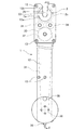
図1及び図2を参照して、1は図6に示すタイロッドCのナットC4を締付けるオープンエンドレンチのレンチ本体を示している。レンチ本体1は、半割りしたケース状の2半部11,12を複数のボルト13で締結して成るもので、中空になっている。両半部11,12の先端部間には、回転体2が挟み込まれている。そして、各半部11,12の先端部に互に同心の円形孔11a,12aを形成し、各円形孔11a,12aに回転体2の両側面に突設した軸部2a,2aを嵌合させて、回転体2を両円形孔11a,12aの中心を結ぶ軸線O回りに回転自在に軸支している。
【0008】
また、レンチ本体1の両半部11,12の先端に、軸状ワークたるタイロッドCのロッド本体C1の挿入ガイド用の切欠き11b,12bを円形孔11a,12aに達するように形成すると共に、回転体2に、周面に開口するロッド本体C1用の挿入溝2bを形成している。かくて、回転体2を切欠き11b,12bに挿入溝2bが合致する位相にすれば、挿入溝2bにロッド本体C1を切欠き11b,12bを通して径方向に挿入できる。
【0009】
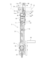
また、レンチ本体1には、回転体2を回転させる駆動手段3が設けられている。駆動手段3は、図2に示す如く、レンチ本体1の尾端部内に設けた歯付きプーリ30と、レンチ本体1の先端部寄りの部分に設けた、プーリ30に歯付きベルト31を介して連結される歯付きプーリ32と、プーリ32に固定したギア33と、ギア33に噛合する1対のギア34,34とで構成されており、回転体2の外周面に形成したギア2cをギア34,34に噛合させ、プーリ30をこれに連結したハンドル35で回転させることにより、ベルト31とプーリ32とギア33とギア34,34とを介して回転体2が回転されるようにしている。尚、プーリ30は、レンチ本体1の長手方向にねじ36で位置調整自在に設けた可動枠37に軸支されており、可動枠37の位置調整でベルト31の張力を調整し得るようにしている。
【0010】
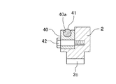
また、回転体2の軸方向一側面には、タイロッドCに外挿したナットC4を軸方向に挿入可能なソケット部4が設けられている。このソケット部4は、図3に示す如く、回転体2の軸方向一側面に埋設した4個のブロック40により、ナットC4の外形に相似する六角形の挿入溝2b側の2辺を截除した角形の内面を持つように構成されている。そして、各ブロック40で構成される前記角形の内面の各辺に、ローラ41を該各辺と平行に軸支している。各ブロック30には、図4に示す如く、ソケット部4の内方を向く各ブロック40の内表面にスリット状に開口する、前記各辺に平行な軸支穴40aが形成されており、この軸支穴40aにローラ41をその周面の一部がブロック40の内表面から張り出すように嵌挿し、ブロック40の内表面から張り出したローラ41の周面部分がナットC4に係合するようにしている。各ブロック40は、回転体2に形成した各凹溝2dに嵌合させた状態でボルト42により回転体2に固定されており、ローラ41が摩耗したときは、ブロック40を取外してローラ41を交換できるようにしている。
【0011】
車輪のトー調整後のナットC4の締付けに際しては、回転体2の挿入溝2bをレンチ本体1の先端の切欠き11b,12bに合致させた状態で、挿入溝2bにタイロッドCの工具係合部C3を切欠き11b,12bを通して径方向に挿入し、次に、レンチ本体1をナットC4側に動かすと共に、ハンドル35の操作で回転体2を回転させ、回転体2のソケット部4の位相をナットC4の位相に整合させて、ソケット部4をナットC4に軸方向から嵌合させる。次に、回転体2をナットC4の締付方向たる図3の反時計方向に回転させる。これによれば、ソケット部4の各ローラ41が図3に仮想線で示す如くナットC4に係合し、ローラ41を介してナットC4に回転力が伝達されてナットC4が締付けられる。
【0012】
ナットC4の締付けが完了すると、レンチ本体1を動かしてソケット部4をナットC4から軸方向に離脱させるが、この際、ローラ41はナットC4に対し軸方向に転動するから、ナットC4の締付け時にローラ41にナットC4の角部が食い込んでも、ソケット部4はナットC4からスムーズに離脱される。
【0013】
次に、回転体2を回転させ、回転体2の挿入溝2bがレンチ本体1の先端の切欠き11b,12bに合致したところで回転体2の回転を停止し、レンチ本体1をタイロッドCから離脱させる。
【0014】
尚、上記実施形態では、ソケット部4の各辺を構成する各ブロック40に各1本のローラ41を軸支したが、図7に示す如く、各ブロック40に軸方向に並べて2本以上のローラ41を軸支しても良い。
【0015】
以上、手持ち式のオープンエンドレンチに本発明を適用した実施形態について説明したが、自動機に搭載するオープンエンドレンチにも同様に本発明を適用できる。
【0016】
【発明の効果】
以上の説明から明らかなように、本発明によれば、ナットの締付け時にソケット部へのナットの食い付きを生じても、ソケット部をナットから軸方向にスムーズに離脱でき、使い勝手が良好になる。
【図面の簡単な説明】
【図1】 本発明レンチの一例の側面図
【図2】 図1のII-II線截断面図
【図3】 図2のIII-III線で截断した回転体の截断側面図
【図4】 図3のIV-IV線截断面図
【図5】 他の実施形態の図4に対応する截断面図
【図6】 タイロッドの斜視図
【符号の説明】
C タイロッド(ワーク) C4 ナット
1 レンチ本体 2 回転体
2b 挿入溝 4 ソケット部
41 ローラ[0001]
BACKGROUND OF THE INVENTION
The present invention relates to an open end wrench for rotating a nut externally attached to a shaft-like workpiece such as a tie rod incorporated in a steering mechanism of an automobile.
[0002]
[Prior art]
As shown in FIG. 6, a tie rod C that transmits the movement of the relay rod A interlocking with the steering wheel to the knuckle arm B is incorporated in the steering mechanism of the automobile. The tie rod C includes a rod body C1 connected to the relay rod A via a ball joint A1, and a rod end C2 connected to a knuckle arm B via a ball joint B1. The end of the rod body C1 is screwed into the rod end C2, and the length of the tie rod C is increased by rotating the rod body C1 by engaging a wrench with a tool engagement part C3 having a hexagonal cross section formed on the rod body C1. The wheel toe can be adjusted. After the toe adjustment, the nut C4 extrapolated to the rod body C1 is tightened to the rod end C2 side to prevent the rod body C1 from rotating.
[0003]
Conventionally, as an open-end wrench for tightening the nut C4, a rotating body in which an insertion groove into which a shaft-like workpiece can be inserted in a radial direction is formed at the tip of a wrench body according to Japanese Patent Laid-Open No. 1-295766. In addition, it is known that the rotating body is provided with a socket portion into which a nut can be inserted in the axial direction. According to this, if the tie rod is inserted into the insertion groove of the rotating body and the socket portion is engaged with the nut from the axial direction, the nut is tightened without moving the wrench body simply by rotating the rotating body thereafter. Can be done easily.
[0004]
[Problems to be solved by the invention]
In the conventional open-end wrench described above, when the nut is tightened, each corner of the outer surface of the nut may bite into each side of the rectangular inner surface of the socket, and the socket cannot be detached from the nut in the axial direction.
[0005]
In view of the above, an object of the present invention is to provide an open-end wrench that can smoothly remove the socket portion from the nut in the axial direction after the nut is tightened.
[0006]
[Means for Solving the Problems]
In order to solve the above-mentioned problems, the present invention is an open end wrench for rotating a nut externally attached to a shaft-shaped workpiece, and is an insert capable of inserting the shaft-shaped workpiece in the radial direction at the tip of the wrench body. A rotating body having a groove is pivotally supported, and the rotating body is provided with a socket part into which the nut can be inserted in the axial direction. A roller that can be engaged with the nut is provided on each side of the rectangular inner surface of the socket part. The shaft is supported in parallel with each side.
According to the present invention, when the nut is inserted into the socket portion and the rotating body is rotated, the roller is engaged with the nut and the nut is tightened. Then, after tightening the nut, the socket part is detached from the nut in the axial direction. At this time, the roller rolls in the axial direction with respect to the nut. Therefore, even if the corner portion of the nut bites into the roller when the nut is tightened, the socket portion can be smoothly detached from the nut in the axial direction.
[0007]
DETAILED DESCRIPTION OF THE INVENTION
1 and 2,
[0008]
Further,
[0009]
Further, the
[0010]
Further, on one side surface of the rotating
[0011]
When tightening the nut C4 after adjusting the wheel toe, the tool engaging portion of the tie rod C is inserted into the
[0012]
When the tightening of the nut C4 is completed, the
[0013]
Next, the
[0014]
In the above-described embodiment, each
[0015]
As mentioned above, although embodiment which applied this invention to the hand-held type open end wrench was described, this invention is applicable similarly to the open end wrench mounted in an automatic machine.
[0016]
【The invention's effect】
As is apparent from the above description, according to the present invention, even when the nut bites into the socket portion when the nut is tightened, the socket portion can be smoothly detached from the nut in the axial direction, and the usability is improved. .
[Brief description of the drawings]
1 is a side view of an example of the wrench of the present invention. FIG. 2 is a cross-sectional view taken along line II-II in FIG. 1. FIG. 3 is a cut-away side view of a rotating body cut along line III-III in FIG. 3 is a cross-sectional view taken along the line IV-IV in FIG. 3. FIG. 5 is a cross-sectional view taken along the line corresponding to FIG. 4 in another embodiment.
C tie rod (workpiece)
Claims (1)
レンチ本体の先端部に、軸状ワークを径方向に挿入可能な挿入溝を形成した回転体を軸支し、この回転体に、ナットを軸方向に挿入可能なソケット部を設けるものにおいて、
ソケット部の角形の内面の各辺に、ナットに係合可能なローラを該各辺と平行に軸支する、
ことを特徴とするオープンエンドレンチ。An open-end wrench for rotating a nut extrapolated to a shaft-shaped workpiece,
In the tip of the wrench body, a rotating body in which an insertion groove capable of inserting a shaft-shaped workpiece in the radial direction is pivotally supported, and a socket portion in which a nut can be inserted in the axial direction is provided on the rotating body.
On each side of the rectangular inner surface of the socket part, a roller that can be engaged with the nut is pivotally supported in parallel with each side.
An open-end wrench characterized by
Priority Applications (1)
| Application Number | Priority Date | Filing Date | Title |
|---|---|---|---|
| JP08565199A JP3961712B2 (en) | 1999-03-29 | 1999-03-29 | Open end wrench |
Applications Claiming Priority (1)
| Application Number | Priority Date | Filing Date | Title |
|---|---|---|---|
| JP08565199A JP3961712B2 (en) | 1999-03-29 | 1999-03-29 | Open end wrench |
Publications (2)
| Publication Number | Publication Date |
|---|---|
| JP2000280180A JP2000280180A (en) | 2000-10-10 |
| JP3961712B2 true JP3961712B2 (en) | 2007-08-22 |
Family
ID=13864743
Family Applications (1)
| Application Number | Title | Priority Date | Filing Date |
|---|---|---|---|
| JP08565199A Expired - Fee Related JP3961712B2 (en) | 1999-03-29 | 1999-03-29 | Open end wrench |
Country Status (1)
| Country | Link |
|---|---|
| JP (1) | JP3961712B2 (en) |
-
1999
- 1999-03-29 JP JP08565199A patent/JP3961712B2/en not_active Expired - Fee Related
Also Published As
| Publication number | Publication date |
|---|---|
| JP2000280180A (en) | 2000-10-10 |
Similar Documents
| Publication | Publication Date | Title |
|---|---|---|
| US4821611A (en) | Tightening device | |
| CN101541482A (en) | Additional hand grip having an eccentric tension lever for a hand machine tool | |
| TWI624331B (en) | Automatic speed speed ratchet wrench | |
| US20020194739A1 (en) | Manually guided implement | |
| US7448300B2 (en) | 360 degree rotatable ratchet socket drive body tapered for various axially driven external driving components | |
| JP2000506448A (en) | Power nutrunner with torque release clutch and adjustment tool | |
| JP3961712B2 (en) | Open end wrench | |
| KR20000034953A (en) | Fastener-driving accessory for rotary driving tool | |
| JP3634185B2 (en) | Tie rod adjustment device | |
| KR200203399Y1 (en) | Division type wrench | |
| CA1278933C (en) | Powered pipe wrench | |
| JP3961711B2 (en) | Open end wrench | |
| ES2368435T3 (en) | MANUBRIO, SPINDLE SYSTEM AND MANUFACTURING PROCEDURE FOR A MANUBRIO. | |
| JPWO2020166525A1 (en) | Linear shaft and its manufacturing method | |
| JPH11117535A (en) | Continuous rotating equipment for threaded joint for coupling threaded reinforcing bar | |
| JPH08168971A (en) | Impact wrench | |
| JP4402242B2 (en) | Open end wrench | |
| JP3874504B2 (en) | Tool changer | |
| KR200253184Y1 (en) | Checkchain for tractor | |
| JP4489895B2 (en) | How to use an open-end wrench | |
| KR101995445B1 (en) | And anti-insertion Combination wrench | |
| JP4261663B2 (en) | Rotating tool holder and machine tool using the same | |
| GB2034619A (en) | Gear-drive hand tool | |
| WO2002085576A1 (en) | Adjustable wrench/socket with simultaneousely movable jaws | |
| JPH0435861A (en) | Adjusting device for wear of brush |
Legal Events
| Date | Code | Title | Description |
|---|---|---|---|
| A621 | Written request for application examination |
Free format text: JAPANESE INTERMEDIATE CODE: A621 Effective date: 20051205 |
|
| RD03 | Notification of appointment of power of attorney |
Free format text: JAPANESE INTERMEDIATE CODE: A7423 Effective date: 20070315 |
|
| TRDD | Decision of grant or rejection written | ||
| A01 | Written decision to grant a patent or to grant a registration (utility model) |
Free format text: JAPANESE INTERMEDIATE CODE: A01 Effective date: 20070515 |
|
| A61 | First payment of annual fees (during grant procedure) |
Free format text: JAPANESE INTERMEDIATE CODE: A61 Effective date: 20070517 |
|
| R150 | Certificate of patent or registration of utility model |
Free format text: JAPANESE INTERMEDIATE CODE: R150 |
|
| FPAY | Renewal fee payment (event date is renewal date of database) |
Free format text: PAYMENT UNTIL: 20110525 Year of fee payment: 4 |
|
| FPAY | Renewal fee payment (event date is renewal date of database) |
Free format text: PAYMENT UNTIL: 20110525 Year of fee payment: 4 |
|
| LAPS | Cancellation because of no payment of annual fees |