JP3961721B2 - Hybrid vehicle drive system - Google Patents
Hybrid vehicle drive system Download PDFInfo
- Publication number
- JP3961721B2 JP3961721B2 JP19094599A JP19094599A JP3961721B2 JP 3961721 B2 JP3961721 B2 JP 3961721B2 JP 19094599 A JP19094599 A JP 19094599A JP 19094599 A JP19094599 A JP 19094599A JP 3961721 B2 JP3961721 B2 JP 3961721B2
- Authority
- JP
- Japan
- Prior art keywords
- engine
- main battery
- battery
- power
- abnormality
- Prior art date
- Legal status (The legal status is an assumption and is not a legal conclusion. Google has not performed a legal analysis and makes no representation as to the accuracy of the status listed.)
- Expired - Fee Related
Links
Images




Classifications
-
- Y—GENERAL TAGGING OF NEW TECHNOLOGICAL DEVELOPMENTS; GENERAL TAGGING OF CROSS-SECTIONAL TECHNOLOGIES SPANNING OVER SEVERAL SECTIONS OF THE IPC; TECHNICAL SUBJECTS COVERED BY FORMER USPC CROSS-REFERENCE ART COLLECTIONS [XRACs] AND DIGESTS
- Y02—TECHNOLOGIES OR APPLICATIONS FOR MITIGATION OR ADAPTATION AGAINST CLIMATE CHANGE
- Y02T—CLIMATE CHANGE MITIGATION TECHNOLOGIES RELATED TO TRANSPORTATION
- Y02T10/00—Road transport of goods or passengers
- Y02T10/60—Other road transportation technologies with climate change mitigation effect
- Y02T10/62—Hybrid vehicles
-
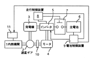
- Y—GENERAL TAGGING OF NEW TECHNOLOGICAL DEVELOPMENTS; GENERAL TAGGING OF CROSS-SECTIONAL TECHNOLOGIES SPANNING OVER SEVERAL SECTIONS OF THE IPC; TECHNICAL SUBJECTS COVERED BY FORMER USPC CROSS-REFERENCE ART COLLECTIONS [XRACs] AND DIGESTS
- Y02—TECHNOLOGIES OR APPLICATIONS FOR MITIGATION OR ADAPTATION AGAINST CLIMATE CHANGE
- Y02T—CLIMATE CHANGE MITIGATION TECHNOLOGIES RELATED TO TRANSPORTATION
- Y02T10/00—Road transport of goods or passengers
- Y02T10/60—Other road transportation technologies with climate change mitigation effect
- Y02T10/70—Energy storage systems for electromobility, e.g. batteries
Landscapes
- Electric Propulsion And Braking For Vehicles (AREA)
- Hybrid Electric Vehicles (AREA)
- Control Of Vehicle Engines Or Engines For Specific Uses (AREA)
- Control Of Charge By Means Of Generators (AREA)
Description
【0001】
【発明の属する技術分野】
本発明は、ハイブリッド車の駆動装置に関する。
【0002】
【従来の技術】
エンジンと、主電池と、エンジン、主電池および車両駆動軸の間でエネルギ−伝達を行うエネルギ−伝達装置と、このエネルギ−伝達装置を制御する制御装置とを備えるハイブリッド車のエネルギ−伝達装置としては、各種のものが知られており、たとえば特開平9−46966号公報や特開平10−42600号公報のハイブリッド車の駆動装置では、エネルギ−伝達装置は、エンジンの出力軸から車両駆動軸への電磁的なトルク伝達を行うとともにエンジントルクの一部または全部を電気エネルギーに変換する第1の回転電機と、車両駆動軸と電磁的なトルクの授受を行う第2の回転電機とを備えている。
【0003】
この種のハイブリッド車の駆動装置のエネルギ−伝達装置の制御装置は、一般に車両要求エネルギ−(走行動力や補機などへの給電電力)と電池の要求電力との和がエンジン出力に一致するようになされ、特に、エンジンのエミッション低減や燃費向上の要請から低速低トルク走行時やアイドル時などではできるだけエンジンを停止させるモ−ドで動作するように動作モ−ドを設定されるのが通常である。
【0004】
また、従来のハイブリッド車では、主電池の電圧、電流、温度などを電池制御装置によりモニタし、この電池制御装置が主電池の異常を検出した場合には、主電池とエネルギ−伝達装置との間に介設されたマグネットスイッチ(メインリレ−)を開いて(遮断して)、主電池の保護を行っている。
【0005】
【発明が解決しようとする課題】
しかしながら、上述したように従来のハイブリッド車では、主電池の異常を検出した場合、マグネットスイッチを即時に遮断して主電池保護を行っているので、もし走行中または交差点などでの一時停車中でかつエンジン停止中にこのような主電池異常が発生すると、上述した主電池保護のためのマグネットスイッチの遮断により、その後のエンジン始動が不可能となり、車両が立ち往生してしまうという不具合が生じ、交通が混乱する可能性が生じた。
【0006】
本発明は上記問題点に鑑みなされたものであり、車両走行機能の低下を回避しつつ主電池保護機能を確保可能なハイブリッド車の駆動装置を提供することを、その解決すべき課題としている。
【0007】
【課題を解決するための手段】
すべての請求項記載の本発明のハイブリッド車の駆動装置では、エネルギ−伝達装置は、エンジン、主電池および車両駆動軸の間のエネルギーの授受を制御し、特に、エンジン動力を電力に変換して主電池を充電し、主電池の電力を動力に変換してエンジンを始動する1ないし複数の回転電機を有している。
【0008】
請求項1記載の構成では特に、走行モ−ド、すなわちイグニッションキ−がオン状態となっていて走行中または一時停止中で、かつ、エンジンが停止している状態で主電池の異常を検出した場合に、エンジンの始動を指令し、エンジンの始動完了後に開閉装置を遮断して主電池の充放電を禁止し、走行モ−ド中における制御装置によるエンジンの停止を禁止し、主電池の電力授受を伴わない制御モ−ドでエネルギ−伝達装置を作動させる。
【0009】
すなわち、本構成によれば、走行モ−ドで主電池に異常が生じた場合は、かならずエンジンを動作状態としてから主電池を切り離すので、エンジン停止中に主電池異常による主電池切り離しが生じてエンジンによる走行が不可能になるという問題が生じることがない。
【0010】
なお、エンジン始動電力量自体は主電池にとってそれほど大きなものではないので、異常検出後のエンジン始動による主電池異常が格段に悪化するということはほとんどない。
【0011】
更に、本構成では、このエンジンの始動完了後は、走行モ−ド中における制御装置によるエンジンの停止を禁止するので、イグニッションキ−をオフするまでは車両走行を確保することができる。
【0012】
その上、エネルギ−伝達装置は、主電池の電力授受を伴わない制御モ−ドでエネルギ−伝達装置を作動させるので、更に具体的に言えば車両の走行などに必要なエネルギ−はエンジンから供給するので(補機バッテリを有する場合における補機バッテリによる補機などへの給電を除いて)、主電池が切断されているのに主電池が正常な場合のモ−ドでエネルギ−伝達装置が運転されるという不具合を回避することができる。
【0013】
なお、本構成において、主電池の異常とは、たとえば電圧や電流が過大な状態や温度が過度に上昇した状態を含む。
【0014】
開閉装置としてはマグネットスイッチ(電磁開閉器)が好適であるが、電力用半導体スイッチング素子を用いてもよい。
【0015】
走行モ−ドとは、上述のようにイグニッションキ−をオンした状態を言う。
【0016】
エンジンが停止している状態とは、エンジンが停止している状態、又は、エンジンが始動完了後の最低回転数未満の回転数で回転する状態をいう。
【0017】
走行モ−ド中におけるエンジンの停止とは、エンジンが始動完了後の最低回転数を超える回転数で燃料消費せずに回転する状態を含まない。走行モ−ド中におけるエンジンの停止の禁止とは、イグニッションキ−をオンしている状態でエンジン回転数が始動完了後の最低回転数以下の状態にまで低下することを禁止することを意味する。
【0025】
【発明を実施するための態様】
本発明のハイブリッド車の駆動装置の好適な態様を以下の実施例を参照して説明する。
【0026】
【実施例1】
本発明のハイブリッド車の駆動装置の一実施例を以下に説明する。
【0027】
(全体構成)
図1において、1は内燃機関(エンジン)、2は遊星ギヤ機構、3はブラシレスDCモ−タにより構成されてエンジン駆動の発電機、スタ−タモ−タ、回生制動用発電機として作動可能な第1の回転電機、4はブラシレスDCモ−タにより構成されるトルクアシスト用の第2の回転電機、5は両回転電機3、4を駆動するインバ−タ、6は高圧の主電池、7は主電池6とインバータ5との送電路に設けられたマグネットスイッチ、8はマイコンを含んでインバータ5を制御する走行制御装置、9は主電池6の充電状態を制御する電池制御装置、10はギヤ機構、11は内燃機関制御装置である。
【0028】
遊星ギヤ機構2、第1の回転電機3、第2の回転電機4、インバータ5、ギヤ機構10は本発明で言うエネルギ−伝達装置を構成している。遊星減速歯車機構2は、周知のように、回転軸、回転軸と噛合してその周囲を自転、公転するサンギヤ、サンギヤと噛合してサンギヤの周囲を回転するインタ−ナルギヤとを有し、これら回転軸、サンギヤおよびインタ−ナルギヤが内燃機関1、第1の回転電機3および第2の回転電機4の回転軸に個別に連結されている。ギヤ機構10において第2の回転電機4の回転軸に連結される図示しない車両駆動軸は、クラッチ付きギヤ機構10を通じて車輪に走行トルクを供給する構成となっている。
【0029】
インバ−タ5は、マグネットスイッチ7を通じて主電池6と直流電力を授受するとともに第1の回転電機3と交流電力を授受する三相インバータ回路と、マグネットスイッチ7を通じて主電池6と直流電力を授受するとともに第2の回転電機4と交流電力を授受する三相インバータ回路とを含んでいる。
【0030】
走行制御装置8、電池制御装置9およびは内燃機関制御装置11は本発明で言う制御装置を構成し、マグネットスイッチ7は本発明で言う開閉装置を構成している。主電池6の電圧、電流、温度は電池センサ12で検出されて電池制御装置9に送られる。
【0031】
通常の動作において、電池制御装置9は、検出した主電池6の状態に基づいて電池充電パワ−要求値を決定して走行制御装置8に出力し、走行制御装置8はアクセルペダル踏み量や車両駆動軸回転数などから算出した車両駆動パワ−要求値と上記電池充電パワ−要求値などを加算してエンジンパワ−要求値を決定し、このエンジンパワ−要求値を内燃機関制御装置11に出力し、内燃機関制御装置11はこのエンジンパワ−要求値に等しい出力を最も低い燃料消費率で発生するトルク、回転数で内燃機関1を運転制御する。また、走行制御装置8は、内燃機関1の回転数およびトルクと車両駆動軸の回転数およびトルクとの差に応じてインバ−タ5の制御を行い、第1の回転電機3および第2の回転電機4を発電又は電動動作させる。たとえば通常の巡航走行では、第1の回転電機3に発電動作させ、この発電電力で第2の回転電機4を電動動作させて車両駆動軸の不足トルクを補う。この種のハイブリッド車の基本駆動制御自体はもはや公知であるのでこれ以上の説明は省略する。
【0032】
以下、本発明の要旨である主電池異常時の対応処理に関する電池制御装置9および走行制御装置8の動作を図2、図3に示すル−チンを参照して以下に説明する。
【0033】
電池制御装置9は、まず電池センサ12から主電池6の電圧、電流、温度を読み込み(S100)、それらの組み合わせが所定の正常範囲内かどうかを調べ(S102)、上記組み合わせが上記正常範囲を逸脱している場合には主電池6は異常と判定してそれを走行制御装置8に出力する(S104)。
【0034】
走行制御装置8は、走行モ−ドにおいて主電池6が異常であるとの情報を受信した場合(S200)には、それ以後の走行モ−ド中におけるエンジン停止を禁止し(S202、S204)、エンジン停止に相当する状態と判定した場合には内燃機関1の最低持続回転数値より少し高いアイドル回転数でアイドル回転させる。
【0035】
次に、電池制御装置9は、走行モ−ドにおいて主電池6が異常と判定した場合に内燃機関1が停止状態(エンジン自己連続回転可能な最低回転数値以下)であるかどうかを調べ(S106)、停止状態であればインバ−タ5に発電機9の駆動を指令するとともに内燃機関制御装置11に内燃機関始動動作を指令し(S108)、これにより発電機9が内燃機関1を始動する。
【0036】
次に、電池制御装置9は、走行制御装置8又はインバ−タ5から受信した情報に基づいて内燃機関1の始動が完了したかどうかすなわちエンジン回転数が自己連続回転可能な値以上となったかどうかを調べて始動が完了するまで待機し(S110)、始動が完了したらインバ−タ5にエンジン始動用の上記電動動作の停止を指令し(S112)、更に走行制御装置8にマグネットスイッチ7の遮断を指令し(S114)、走行制御装置8はこの指令を受けて(S206)、マグネットスイッチ7を遮断する(S208)。更に、走行制御装置8は、主電池6の電力授受を伴わない制御モ−ドでエネルギ−伝達装置を作動させる。換言すれば、アクセルペダル踏み量で計算される車両駆動トルクと車両駆動軸の回転数とを掛けて算出した車両駆動パワ−要求値と第1の回転電機3又は第2の回転電機4から高圧補機などへ給電する電力との合計に一致する出力値のうち、最も低燃費の動作点で内燃機関1を駆動制御させる。
【0037】
また、S102において、上記組み合わせが所定の正常範囲内であれば、マグネットスイッチ7を遮断中かどうかを調べ(S116)、遮断中であれば、電池電流を読み込んで(S118)、読み込んだ電池電流が予め記憶する所定値以下であるかを調べ(S120)、電池電流が所定値を超えていればメインルーチンにリターンするか又はS100へ戻り、電池電流が所定値未満であればS122へ進んでマグネットスイッチ7をオンを指令し、主電池6が正常であることを通報する(S124)。
【0038】
走行制御装置8は、上記したマグネットスイッチ7の導通および上記主電池6が正常であることを受信した場合には、それ以後の走行モ−ド中におけるエンジン停止を許可し(S210)、マグネットスイッチ7をオンする(S212)。
【0039】
(変形態様)
上記説明した実施例では、電池制御装置9により、主電池6の異常検出時の対応動作の大部分を担当させたが、電池制御装置9が電池異常検出のみを行い、走行制御装置8により残りの電池異常対応動作を負担させてもよいことは明らかである。
【0040】
(実施例効果)
上記説明したこの実施例によれば、主電池6の異常を検出しても、走行モ−ドにもかかわらず内燃機関1の回転数が持続回転可能な最低回転数以下であれば、内燃機関1を始動させてから主電池6を切り離すようにしたので、車両走行機能の低下を回避しつつ主電池保護機能を確保することができる。
【0041】
また、本構成では、この内燃機関1の始動完了後は、走行モ−ド中における制御装置による(イグニッションキ−オフでない)内燃機関1の停止を禁止するので、イグニッションキ−をオフするまでは車両走行を確保することができる。
【0042】
また、エネルギ−伝達装置は、主電池の電力授受を伴わない制御モ−ドでエネルギ−伝達装置を作動させるので、更に具体的に言えば車両の走行などに必要なエネルギ−はエンジンから供給するので、主電池が切断されているのに主電池が正常な場合のモ−ドでエネルギ−伝達装置が運転されるという不具合を回避することができる。
【0043】
更に、温度低下などで、主電池6の状態が正常に回復すれば、再度エンジン停止を含む走行モ−ドでの運転が可能となるので、燃費向上やエミッション低減を図ることができる。
【0044】
【実施例2】
本発明のハイブリッド車の駆動装置の他実施例を図4、図5に示すル−チンを参照して以下に説明する。
【0045】
図4に示すル−チンでは、図2に示すS102とS104との間にて次のル−チンを実施する。すなわち、S102にて異常を検出した場合、この異常が軽度かどうかを調べ(S1220)、軽度であれば軽度異常という情報を走行制御装置8に出力する(S124)。
【0046】
走行制御装置8は、図3に示すS200とS202との間にて次のル−チンを実施する(図5参照)。すなわち、受信した異常が軽度異常であるかどうかを調べ(S2120)、軽度異常であれば主電池6の充放電電流の最大値を所定しきい値以下と規制し、更に所定時間内の充放電累積時間を所定しきい値以下に規制する(S214)。
【0047】
なお、この実施例における軽度異常は、停止中の内燃機関1を始動するに必要な電力を主電池6から給電可能なレベルの異常であり、S214における充放電電流の最大値および所定時間内の充放電累積時間の規制は、内燃機関1の始動が可能なレベルに設定するものとする。なお、この種の主電池6の充放電電流値および充放電累積時間の規制はインバ−タ5の制御により簡単に実施することができる。
【0048】
このようにすれば、主電池6の蓄電電力による大電力トルクアシストや大電力回生制動はできないものの、走行モ−ドにおけるエンジン停止および小規模なトルクアシストや回生制動は維持でき、主電池6の異常の深刻化を抑止しつつ走行性向上や燃費低減やエミッション低減を実現することができる。
【0049】
【実施例3】
本発明のハイブリッド車の駆動装置の他実施例を図6に示すル−チンを参照して以下に説明する。
【0050】
このル−チンでは、図5に示すS214とS202との間にて、エンジン停止条件を狭化する(S216)。つまり、本来の制御でエンジン停止を許可(S210)するべきところであっても、一部の条件を満足できない場合にはエンジンのアイドル運転に留める。
【0051】
なお、上記一部の条件としては、たとえばエンジン回転数およびエンジントルクが所定値未満の状態が所定時間持続するに至らない場合が挙げられる。これにより、主電池6の軽度異常(たとえば主電池6のある程度の温度上昇)が生じた場合、エンジンの停止、再始動が頻繁に生じるのを防止し、主電池6の充放電負担を軽減することができる。
【0052】
【実施例4】
本発明のハイブリッド車の駆動装置の他実施例を図7を参照して以下に説明する。
【0053】
この実施例は、図1に示す実施例1において、低圧の補機バッテリ12およびDC−DCコンバ−タ13を追加したものである。なお、補機バッテリ12は図示しない整流装置を通じて第1の回転電機3から充電されるものとする。又は、DC−DCコンバ−タ13に含まれる整流装置を利用して第1の回転電機3が出力する交流電圧を整流し、降圧して補機バッテリ12に給電してもよい。
【0054】
DC−DCコンバ−タ13は、補機バッテリ12の出力を第1の回転電機3を駆動できるレベルまで昇圧してインバ−タ5に給電する。
【0055】
この実施例における電池制御装置9および走行制御装置8の制御について図8および図9のル−チンを参照して以下に説明する。
【0056】
まず、電池制御装置9は、電池センサ12から主電池6の電圧、電流、温度を読み込み(S100)、それらの組み合わせが所定の正常範囲内かどうかを調べ(S102)、上記組み合わせが上記正常範囲を逸脱している場合には主電池6は異常と判定してそれを走行制御装置8に出力し(S104)そうでなければ正常であることを出力する(S140)。
【0057】
走行制御装置8は、走行モ−ドにおいて主電池6が異常であるとの情報を受信した場合(S200)には、マグネットスイッチ7をオフし(S208)、図6で説明したエンジン停止条件の狭化を行い(S216)、エンジン始動要請が生じたかどうかを調べ(S218)、生じたらDC−DCコンバ−タ13を駆動して補機バッテリ12による内燃機関1の始動を行う(S220)。
【0058】
また、S200にて主電池6が正常であると判定した場合には、もしマグネットスイッチ7がオフしていればマグネットスイッチ7をオンし(S212)、上記エンジン停止条件を元の状態まで緩和する(S40)。次に、エンジン始動要請が生じたかどうかを調べ(S242)、生じたら主電池6を用いて内燃機関1の始動を行う(S244)。
【0059】
この実施例によれば、補機バッテリ12によるエンジン始動時にマグネットスイッチ7のオフにより補機バッテリ12が主電池6を充電することがなく、DC−DCコンバ−タ13で昇圧された電力をすべて内燃機関1の始動に回せるので、補機バッテリ12の負担が少ない利点がある。
【図面の簡単な説明】
【図1】 実施例1のハイブリッド車の駆動装置の電気系統図である。
【図2】 図1の電池制御装置の異常対応制御動作を示すフローチャートである。
【図3】 図1の走行制御装置の異常対応制御動作を示すフローチャートである。
【図4】 実施例2の電池制御装置の異常対応制御動作を示すフローチャートである。
【図5】 実施例2の走行制御装置の異常対応制御動作を示すフローチャートである。
【図6】 実施例3の走行制御装置の異常対応制御動作を示すフローチャートである。
【図7】 実施例4のハイブリッド車の駆動装置の電気系統図である。
【図8】 図7の電池制御装置の異常対応制御動作を示すフローチャートである。
【図9】 図7の走行制御装置の異常対応制御動作を示すフローチャートである。
【符号の説明】
1は内燃機関、2は遊星ギヤ機構(エネルギ−伝達装置)、3は第1の回転電機(エネルギ−伝達装置)、4は第2の回転電機(エネルギ−伝達装置)、5はインバ−タ(エネルギ−伝達装置)、6は主電池、7はマグネットスイッチ(開閉装置)、8は走行制御装置(制御装置)、9は電池制御装置(制御装置)、10はギヤ機構(エネルギ−伝達装置)、11は内燃機関制御装置(制御装置)[0001]
BACKGROUND OF THE INVENTION
The present invention relates to a drive device for a hybrid vehicle.
[0002]
[Prior art]
As an energy transmission device for a hybrid vehicle, including an engine, a main battery, an energy transmission device that transmits energy between the engine, the main battery, and the vehicle drive shaft, and a control device that controls the energy transmission device Are known. For example, in a hybrid vehicle drive device disclosed in Japanese Patent Laid-Open Nos. 9-46966 and 10-42600, the energy transmission device is connected from the engine output shaft to the vehicle drive shaft. A first rotating electric machine that performs electromagnetic torque transmission and converts part or all of the engine torque into electric energy, and a second rotating electric machine that transfers electromagnetic torque to and from the vehicle drive shaft. Yes.
[0003]
In general, a control device for an energy transmission device of a drive device of this type of hybrid vehicle is such that the sum of vehicle required energy (power supplied to driving power, auxiliary equipment, etc.) and battery required power matches the engine output. In particular, the operating mode is usually set to operate in a mode that stops the engine as much as possible during low-speed, low-torque driving or idling due to demands for reducing engine emissions and improving fuel economy. is there.
[0004]
Further, in the conventional hybrid vehicle, the voltage, current, temperature, etc. of the main battery are monitored by the battery control device, and when the battery control device detects an abnormality of the main battery, the main battery and the energy transfer device are not connected. A magnet switch (main relay) interposed therebetween is opened (blocked) to protect the main battery.
[0005]
[Problems to be solved by the invention]
However, as described above, in the conventional hybrid vehicle, when the abnormality of the main battery is detected, the magnet switch is immediately shut off to protect the main battery, so if the vehicle is traveling or temporarily stopped at an intersection, etc. If such a main battery abnormality occurs while the engine is stopped, the magnet switch for the main battery protection described above is shut off, which makes it impossible to start the engine thereafter and causes the vehicle to become stuck. There was a possibility of confusion.
[0006]
The present invention has been made in view of the above problems, and an object to be solved is to provide a drive device for a hybrid vehicle capable of ensuring a main battery protection function while avoiding a decrease in vehicle travel function.
[0007]
[Means for Solving the Problems]
In the hybrid vehicle drive device of the present invention, the energy transmission device controls the transfer of energy between the engine, the main battery and the vehicle drive shaft, and in particular converts the engine power into electric power. It has one or more rotating electrical machines that charge the main battery and convert the power of the main battery into power to start the engine.
[0008]
In particular, the abnormality of the main battery is detected when the driving mode, i.e., the ignition key is on, the vehicle is running or temporarily stopped, and the engine is stopped. In this case, the engine is instructed to start, and after the engine has been started, the switchgear is shut off to prohibit charging / discharging of the main battery, and the engine is prohibited from being stopped by the control device in the running mode. The energy transmission device is operated in a control mode without transfer.
[0009]
In other words, according to this configuration, when the main battery has an abnormality in the running mode, the main battery is disconnected after the engine is in an operating state. Therefore, the main battery is disconnected due to the main battery abnormality while the engine is stopped. There is no problem that the engine cannot be run.
[0010]
Since the engine starting power amount itself is not so large for the main battery, the main battery abnormality due to the engine starting after the abnormality detection is hardly deteriorated.
[0011]
Further, in this configuration, after the start of the engine is completed, the stop of the engine by the control device in the travel mode is prohibited, so that the vehicle travel can be ensured until the ignition key is turned off.
[0012]
In addition, since the energy transmission device operates the energy transmission device in a control mode that does not involve the power transfer of the main battery, more specifically, the energy required for traveling of the vehicle is supplied from the engine. Therefore, the energy transmission device is operated in the mode when the main battery is normal although the main battery is disconnected, except for the power supply to the auxiliary machine by the auxiliary battery when the auxiliary battery is provided. The problem of driving can be avoided.
[0013]
In this configuration, the abnormality of the main battery includes, for example, a state where the voltage or current is excessive or a state where the temperature is excessively increased.
[0014]
A magnet switch (electromagnetic switch) is suitable as the switchgear, but a power semiconductor switching element may be used.
[0015]
The traveling mode refers to a state where the ignition key is turned on as described above.
[0016]
The state where the engine is stopped refers to a state where the engine is stopped or a state where the engine rotates at a rotational speed less than the minimum rotational speed after completion of starting.
[0017]
Stopping the engine in the running mode does not include a state in which the engine rotates without consuming fuel at a rotational speed exceeding the minimum rotational speed after completion of starting. The prohibition of the engine stop in the running mode means that the engine speed is prohibited from decreasing to a state equal to or lower than the minimum speed after the completion of the start-up with the ignition key turned on. .
[0025]
BEST MODE FOR CARRYING OUT THE INVENTION
Preferred embodiments of the hybrid vehicle drive device of the present invention will be described with reference to the following examples.
[0026]
[Example 1]
An embodiment of the hybrid vehicle drive device of the present invention will be described below.
[0027]
(overall structure)
In FIG. 1, 1 is an internal combustion engine (engine), 2 is a planetary gear mechanism, 3 is a brushless DC motor, and can operate as an engine-driven generator, a starter motor, and a regenerative braking generator. First rotating
[0028]
The
[0029]
The
[0030]
The
[0031]
In normal operation, the battery control device 9 determines a battery charge power request value based on the detected state of the
[0032]
The operations of the battery control device 9 and the
[0033]
The battery control device 9 first reads the voltage, current, and temperature of the
[0034]
When the
[0035]
Next, when it is determined that the
[0036]
Next, the battery control device 9 determines whether or not the start of the internal combustion engine 1 has been completed based on the information received from the
[0037]
In S102, if the above combination is within a predetermined normal range, it is checked whether the
[0038]
When the traveling
[0039]
(Modification)
In the embodiment described above, the battery control device 9 is responsible for most of the corresponding operations when the abnormality of the
[0040]
(Example effect)
According to the embodiment described above, if an abnormality of the
[0041]
Further, in this configuration, after the start of the internal combustion engine 1 is completed, the control device in the traveling mode is prohibited from stopping the internal combustion engine 1 (not the ignition key off). Therefore, until the ignition key is turned off. Vehicle travel can be ensured.
[0042]
Further, since the energy transmission device operates the energy transmission device in a control mode that does not involve the power transfer of the main battery, more specifically, the energy necessary for driving the vehicle is supplied from the engine. Therefore, it is possible to avoid the problem that the energy transmission device is operated in the mode when the main battery is normal even though the main battery is disconnected.
[0043]
Further, if the state of the
[0044]
[Example 2]
Another embodiment of the hybrid vehicle drive device of the present invention will be described below with reference to the routine shown in FIGS.
[0045]
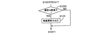
In the routine shown in FIG. 4, the next routine is executed between S102 and S104 shown in FIG. That is, when an abnormality is detected in S102, it is checked whether the abnormality is minor (S122 0 ), and if it is minor, information indicating a minor abnormality is output to the travel control device 8 (S124).
[0046]
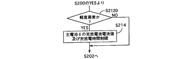
The traveling
[0047]
The minor abnormality in this embodiment is an abnormality at a level at which power necessary for starting the stopped internal combustion engine 1 can be supplied from the
[0048]
In this way, although the high power torque assist and the large power regenerative braking by the stored power of the
[0049]
[Example 3]
Another embodiment of the hybrid vehicle drive device of the present invention will be described below with reference to the routine shown in FIG.
[0050]
In this routine, the engine stop condition is narrowed between S214 and S202 shown in FIG. 5 (S216). That is, even if the engine stop should be permitted under the original control (S210) , if some conditions cannot be satisfied, the engine is kept idle.
[0051]
As some of the above conditions, for example, a case where the engine speed and the engine torque are less than a predetermined value does not last for a predetermined time. As a result, when a minor abnormality of the main battery 6 (for example, a certain temperature rise of the main battery 6) occurs, the engine is prevented from frequently stopping and restarting, and the charge / discharge burden of the
[0052]
[Example 4]
Another embodiment of the hybrid vehicle drive device of the present invention will be described below with reference to FIG.
[0053]
In this embodiment, a low-voltage
[0054]
The DC-
[0055]
Control of the battery control device 9 and the
[0056]
First, the battery control device 9 reads the voltage, current, and temperature of the
[0057]
When the
[0058]
If it is determined in S200 that the
[0059]
According to this embodiment, when the engine is started by the
[Brief description of the drawings]
FIG. 1 is an electrical system diagram of a hybrid vehicle drive device according to a first embodiment.
FIG. 2 is a flowchart showing an abnormality handling control operation of the battery control device of FIG. 1;
FIG. 3 is a flowchart showing an abnormality handling control operation of the travel control device of FIG. 1;
FIG. 4 is a flowchart illustrating an abnormality handling control operation of the battery control device according to the second embodiment.
FIG. 5 is a flowchart showing an abnormality handling control operation of the travel control apparatus according to the second embodiment.
FIG. 6 is a flowchart illustrating an abnormality handling control operation of the travel control device according to the third embodiment.
FIG. 7 is an electrical system diagram of a hybrid vehicle drive apparatus according to a fourth embodiment.
8 is a flowchart showing an abnormality handling control operation of the battery control device of FIG.
FIG. 9 is a flowchart showing an abnormality handling control operation of the travel control device of FIG. 7 ;
[Explanation of symbols]
1 is an internal combustion engine, 2 is a planetary gear mechanism (energy transmission device), 3 is a first rotating electrical machine (energy transmission device), 4 is a second rotating electrical machine (energy transmission device), and 5 is an inverter. (Energy transmission device), 6 is a main battery, 7 is a magnet switch (opening / closing device), 8 is a travel control device (control device), 9 is a battery control device (control device), and 10 is a gear mechanism (energy transmission device). ), 11 is an internal combustion engine control device (control device)
Claims (1)
前記制御装置は、主電池の異常を検出した場合に前記主電池の異常が前記エンジンを始動するのに必要な電力を給電可能なレベルの軽度異常かどうかを調べ、前記軽度異常を検出した場合においてイグニッションキーがオンしている状態に相当する走行モ−ド中にもかかわらず前記エンジンが停止している状態のとき、前記主電池からの給電による前記エンジンの始動を指令し、前記エンジンの始動完了後に前記開閉装置を遮断して前記主電池の充放電を禁止し、前記走行モ−ド中における前記エンジンの停止を禁止し、前記主電池の電力授受を伴わない制御モ−ドで前記エネルギ−伝達装置を作動させることを特徴とするハイブリッド車の駆動装置。The engine, the main battery, and energy transfer between the engine, the main battery, and the vehicle drive shaft are controlled, the engine power is converted into electric power to charge the main battery, and the main battery An energy transmission device that converts electric power into power and starts the engine, a control device that controls the energy transmission device, a battery abnormality detection device that detects abnormality of the main battery, the main battery, and the energy A drive device for a hybrid vehicle comprising: an opening and closing device that opens and closes a power transmission path between the transmission device and the transmission device;
When the control device detects an abnormality of the main battery, it checks whether the abnormality of the main battery is a minor abnormality at a level capable of supplying power necessary to start the engine, and detects the minor abnormality When the engine is stopped despite the travel mode corresponding to the state where the ignition key is turned on, the engine is commanded to start by power supply from the main battery . After completion of the start-up, the switchgear is shut off to prohibit charging / discharging of the main battery, the engine is stopped during the traveling mode, and the control mode without power transfer of the main battery is used. A hybrid vehicle drive device characterized by operating an energy transmission device.
Priority Applications (1)
| Application Number | Priority Date | Filing Date | Title |
|---|---|---|---|
| JP19094599A JP3961721B2 (en) | 1999-07-05 | 1999-07-05 | Hybrid vehicle drive system |
Applications Claiming Priority (1)
| Application Number | Priority Date | Filing Date | Title |
|---|---|---|---|
| JP19094599A JP3961721B2 (en) | 1999-07-05 | 1999-07-05 | Hybrid vehicle drive system |
Publications (2)
| Publication Number | Publication Date |
|---|---|
| JP2001025103A JP2001025103A (en) | 2001-01-26 |
| JP3961721B2 true JP3961721B2 (en) | 2007-08-22 |
Family
ID=16266300
Family Applications (1)
| Application Number | Title | Priority Date | Filing Date |
|---|---|---|---|
| JP19094599A Expired - Fee Related JP3961721B2 (en) | 1999-07-05 | 1999-07-05 | Hybrid vehicle drive system |
Country Status (1)
| Country | Link |
|---|---|
| JP (1) | JP3961721B2 (en) |
Cited By (1)
| Publication number | Priority date | Publication date | Assignee | Title |
|---|---|---|---|---|
| CN101641247B (en) * | 2007-03-28 | 2013-09-11 | 丰田自动车株式会社 | Controller and control method of hybrid vehicle |
Families Citing this family (14)
| Publication number | Priority date | Publication date | Assignee | Title |
|---|---|---|---|---|
| JP3661689B2 (en) * | 2003-03-11 | 2005-06-15 | トヨタ自動車株式会社 | Motor drive device, hybrid vehicle drive device including the same, and computer-readable recording medium storing a program for causing a computer to control the motor drive device |
| DE102006016138B4 (en) | 2006-04-06 | 2014-11-20 | Robert Bosch Gmbh | Hybrid drive with emergency start option |
| JP4745879B2 (en) * | 2006-04-06 | 2011-08-10 | 日立ビークルエナジー株式会社 | Hybrid vehicle control system, hybrid vehicle control method, and vehicle storage battery control system |
| JP4854429B2 (en) * | 2006-08-24 | 2012-01-18 | 株式会社日立製作所 | Hybrid railway vehicle |
| JP4983635B2 (en) * | 2008-02-08 | 2012-07-25 | トヨタ自動車株式会社 | POWER OUTPUT DEVICE, ITS CONTROL METHOD, AND VEHICLE |
| JP5099229B2 (en) * | 2008-10-31 | 2012-12-19 | トヨタ自動車株式会社 | Hybrid vehicle and control method thereof |
| JP5391831B2 (en) * | 2009-05-25 | 2014-01-15 | トヨタ自動車株式会社 | Driving device, automobile equipped with the same, and abnormality determination method |
| EP2441616A4 (en) * | 2009-06-10 | 2017-05-17 | Toyota Jidosha Kabushiki Kaisha | Hybrid vehicle and control method thereof |
| JP2013256174A (en) * | 2012-06-12 | 2013-12-26 | Nissan Motor Co Ltd | Drive device for vehicle |
| JP5849888B2 (en) * | 2012-07-26 | 2016-02-03 | トヨタ自動車株式会社 | Hybrid vehicle |
| JP2016011054A (en) * | 2014-06-30 | 2016-01-21 | トヨタ自動車株式会社 | vehicle |
| US10232715B2 (en) | 2015-03-20 | 2019-03-19 | Nissan Motor Co., Ltd. | Vehicle control apparatus for hybrid vehicles |
| JP6387922B2 (en) | 2015-08-21 | 2018-09-12 | 株式会社デンソー | Vehicle control device |
| JP6694156B2 (en) * | 2016-03-30 | 2020-05-13 | 三菱自動車工業株式会社 | Control device for hybrid vehicle |
-
1999
- 1999-07-05 JP JP19094599A patent/JP3961721B2/en not_active Expired - Fee Related
Cited By (1)
| Publication number | Priority date | Publication date | Assignee | Title |
|---|---|---|---|---|
| CN101641247B (en) * | 2007-03-28 | 2013-09-11 | 丰田自动车株式会社 | Controller and control method of hybrid vehicle |
Also Published As
| Publication number | Publication date |
|---|---|
| JP2001025103A (en) | 2001-01-26 |
Similar Documents
| Publication | Publication Date | Title |
|---|---|---|
| JP3961721B2 (en) | Hybrid vehicle drive system | |
| JP3838478B2 (en) | Vehicle power generation control device | |
| JP3568840B2 (en) | Hybrid vehicle control device | |
| JP5836068B2 (en) | Vehicle power supply device, electric vehicle | |
| JP6459945B2 (en) | Control device for electric vehicle | |
| JP2009148073A (en) | Battery charging method and charging device | |
| JPH0879915A (en) | Hybrid car | |
| JP2012228051A (en) | Vehicle power supply system | |
| JP7232095B2 (en) | Control device | |
| CN108437969B (en) | vehicle control device | |
| JP2005045883A (en) | Hybrid vehicle | |
| JP7316519B2 (en) | vehicle power supply controller | |
| JP3045019B2 (en) | Power generation control device for hybrid electric vehicle | |
| US11161420B2 (en) | Vehicle power supply apparatus | |
| JP3672712B2 (en) | Hybrid vehicle | |
| JP2001157306A (en) | Hybrid vehicle control device | |
| JP7484562B2 (en) | Hybrid vehicle control device | |
| JP7204509B2 (en) | vehicle | |
| JP3045015B2 (en) | Control method of hybrid electric vehicle | |
| JP4292730B2 (en) | VEHICLE ACCESSORY DRIVE METHOD AND CONTROL DEVICE | |
| JP3963155B2 (en) | Power supply control device, power output device including the same, and automobile | |
| CN106740169B (en) | Control device for electric vehicle | |
| KR102163964B1 (en) | Engine starting method for hybrid vehicle | |
| JP2020125036A (en) | Power supply system | |
| JP2000145497A (en) | Power unit start control device |
Legal Events
| Date | Code | Title | Description |
|---|---|---|---|
| A621 | Written request for application examination |
Free format text: JAPANESE INTERMEDIATE CODE: A621 Effective date: 20050824 |
|
| A131 | Notification of reasons for refusal |
Free format text: JAPANESE INTERMEDIATE CODE: A131 Effective date: 20060516 |
|
| A521 | Request for written amendment filed |
Free format text: JAPANESE INTERMEDIATE CODE: A523 Effective date: 20060710 |
|
| A02 | Decision of refusal |
Free format text: JAPANESE INTERMEDIATE CODE: A02 Effective date: 20070105 |
|
| A521 | Request for written amendment filed |
Free format text: JAPANESE INTERMEDIATE CODE: A523 Effective date: 20070202 |
|
| A911 | Transfer to examiner for re-examination before appeal (zenchi) |
Free format text: JAPANESE INTERMEDIATE CODE: A911 Effective date: 20070312 |
|
| A912 | Re-examination (zenchi) completed and case transferred to appeal board |
Free format text: JAPANESE INTERMEDIATE CODE: A912 Effective date: 20070413 |
|
| A61 | First payment of annual fees (during grant procedure) |
Free format text: JAPANESE INTERMEDIATE CODE: A61 Effective date: 20070517 |
|
| R150 | Certificate of patent or registration of utility model |
Ref document number: 3961721 Country of ref document: JP Free format text: JAPANESE INTERMEDIATE CODE: R150 Free format text: JAPANESE INTERMEDIATE CODE: R150 |
|
| FPAY | Renewal fee payment (event date is renewal date of database) |
Free format text: PAYMENT UNTIL: 20110525 Year of fee payment: 4 |
|
| FPAY | Renewal fee payment (event date is renewal date of database) |
Free format text: PAYMENT UNTIL: 20120525 Year of fee payment: 5 |
|
| FPAY | Renewal fee payment (event date is renewal date of database) |
Free format text: PAYMENT UNTIL: 20120525 Year of fee payment: 5 |
|
| FPAY | Renewal fee payment (event date is renewal date of database) |
Free format text: PAYMENT UNTIL: 20130525 Year of fee payment: 6 |
|
| FPAY | Renewal fee payment (event date is renewal date of database) |
Free format text: PAYMENT UNTIL: 20140525 Year of fee payment: 7 |
|
| R250 | Receipt of annual fees |
Free format text: JAPANESE INTERMEDIATE CODE: R250 |
|
| R250 | Receipt of annual fees |
Free format text: JAPANESE INTERMEDIATE CODE: R250 |
|
| R250 | Receipt of annual fees |
Free format text: JAPANESE INTERMEDIATE CODE: R250 |
|
| R250 | Receipt of annual fees |
Free format text: JAPANESE INTERMEDIATE CODE: R250 |
|
| R250 | Receipt of annual fees |
Free format text: JAPANESE INTERMEDIATE CODE: R250 |
|
| LAPS | Cancellation because of no payment of annual fees |