JP3961786B2 - Noise analysis method and apparatus, storage medium, and computer program - Google Patents
Noise analysis method and apparatus, storage medium, and computer program Download PDFInfo
- Publication number
- JP3961786B2 JP3961786B2 JP2001168752A JP2001168752A JP3961786B2 JP 3961786 B2 JP3961786 B2 JP 3961786B2 JP 2001168752 A JP2001168752 A JP 2001168752A JP 2001168752 A JP2001168752 A JP 2001168752A JP 3961786 B2 JP3961786 B2 JP 3961786B2
- Authority
- JP
- Japan
- Prior art keywords
- bus
- noise
- transmission direction
- same
- signal transmission
- Prior art date
- Legal status (The legal status is an assumption and is not a legal conclusion. Google has not performed a legal analysis and makes no representation as to the accuracy of the status listed.)
- Expired - Fee Related
Links
Images


Landscapes
- Design And Manufacture Of Integrated Circuits (AREA)
Description
【0001】
【発明の属する技術分野】
本発明は、ノイズ解析方法及び装置、記憶媒体並びにコンピュータプログラムに関し、特に大規模集積回路(LSI)、マルチチップモジュール(MCM)、プリント基板(PCB)等の電子回路をコンピュータ支援設計(CAD)により設計する際に、電子回路で発生し得るノイズを解析するためのノイズ解析方法及び装置、コンピュータにそのようなノイズ解析を行わせるコンピュータプログラムを格納したコンピュータ読み取り可能な記憶媒体並びにそのようなコンピュータプログラムに関する。
【0002】
近年、各種電子回路の小型化や高速化に伴い、電子回路を設計する際のノイズ解析が重要になってきている。電子回路で発生するノイズは、正確に、且つ、高速に解析することが求められる。
【0003】
【従来の技術】
従来、電子回路を設計する際にノイズ解析を行うノイズ解析ツールとしては、様々なものが提案されている。ノイズ解析ツールは、電子回路の実装設計後に回路シミュレータを用いてノイズ解析及びノイズチェックを行い、ノイズを抑えるためのノイズ対策を決定する。電子回路の設計は、決定されたノイズ対策に基いて必要に応じて変更される。このような設計変更の後、再度ノイズ解析及びノイズチェックを行い、ノイズが許容範囲内に収まるまで上記の如き手順を繰り返す。
【0004】
電子回路を設計する際に考慮するべき主なノイズは、反射ノイズとクロストークノイズである。通常、反射ノイズは、ドライバの内部抵抗と伝送線路の特性インピーダンスの不整合により発生する。他方、クロストークノイズは、信号伝送方向、ドライバの駆動能力、隣接するパターンのギャップ等に大きく依存する。通常、クロストークノイズの解析は、隣接するパターンの情報を必要とするため、電子回路の実装設計後に実装設計データを用いてノイズ解析とノイズチェックを行う。ここで、隣接するパターンの情報には、パターンギャップ、パターン同士が平行に走る距離、伝送線路上でパターンが平行になっている位置等を含む。
しかし、従来のノイズ解析方法では、以下に説明するように、バスのノイズ解析を行う際に、信号伝送方向の指定は行っていない。
【0005】
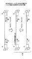
図1は、双方向のネットが3本ある場合のノイズ解析を説明するための図である。ネットとは、電子回路を設計する際に、着目する少なくとも1つの回路素子からなる部分を言う。ここで、例えばドライバ/レシーバCとレシーバ/ドライバD間(以下、C−D間と言う)の伝送信号波形を見る場合、隣接するネット、即ち、ドライバ/レシーバAとレシーバ/ドライバB間(以下、A−B間と言う)の伝送信号波形及びドライバ/レシーバEとレシーバ/ドライバF間(以下、E−F間と言う)の伝送信号波形によるクロストークノイズを考慮する必要がある。
【0006】
この場合、▲1▼のC−>Dの伝送方向に対して、A−B間については、A−>Bの伝送方向とB−>Aの伝送方向とを考慮したクロストークノイズの解析が必要となる。又、▲2▼のD−>Cの伝送方向に対して、A−B間については、やはりA−>Bの伝送方向とB−>Aの伝送方向とを考慮したクロストークノイズの解析が必要となる。又、E−F間についても、同様にして、E−>Fの伝送方向とF−>Eの伝送方向とを考慮したクロストークノイズの解析が必要となる。
【0007】
このため、隣接する配線が多い場合、ノイズ解析に多大な時間が必要となる。又、C−>Dの伝送方向に対し、B−>AやF−>Eの伝送方向はC−>Dの伝送方向とは逆方向であり、この逆方向の伝送によるクロストークノイズは特に大きい。
【0008】
【発明が解決しようとする課題】
例えば、C−D間とE−F間とでは必ず伝送方向が同一であれば、C−>Dの伝送方向に対してF−>Eの伝送方向は存在しない。この場合、C−>Dの伝送方向に対して、F−>Eの伝送方向のノイズ解析を行うことは無駄である。このような無駄なノイズ解析は、ノイズ解析時間を増大させるだけではなく、実際に発生するクロストークノイズよりも大きなノイズが発生するかのようなノイズ解析結果が得られてしまう。
【0009】
つまり、従来のノイズ解析方法では、バスのノイズ解析を行う際に、信号伝送方向の指定は行っていないため、双方向信号のクロストークノイズについて、実際には伝送されない信号の組み合わせについてノイズ解析が行われてしまうという問題があった。このため、無駄なノイズ解析が行われてノイズ解析時間が増大すると共に、実際に発生するクロストークノイズよりも大きなノイズが発生するかのような誤ったノイズ解析結果が得られてしまうという問題もあった。
【0010】
そこで、本発明は、実際には伝送されない信号の組み合わせについての無駄なノイズ解析を防止してノイズ解析時間を短縮すると共に、正確なノイズ解析結果を得ることのできるノイズ解析方法及び装置、記憶媒体並びにコンピュータプログラムを提供することを目的とする。
【0011】
【課題を解決するための手段】
上記課題は、信号の伝送方向が同方向であるバスと、逆方向であるバスとが区別された回路データに基いて、信号の伝送方向が同方向であるバスについては、同方向についてのみクロストークノイズの解析を行うステップを含むことを特徴とするノイズ解析方法によって達成できる。
【0012】
上記の課題は、信号の伝送方向が同方向であるバスと、逆方向であるバスとが区別された回路データに基いて、信号の伝送方向が同方向であるバスについては、同方向についてのみクロストークノイズの解析を行う解析手段を備えたことを特徴とするノイズ解析装置によっても達成できる。
【0013】
上記の課題は、コンピュータにノイズ解析機能を持たせるプログラムが格納されたコンピュータ読み取り可能な記憶媒体であって、前記プログラムは、信号の伝送方向が同方向であるバスと、逆方向であるバスとが区別された回路データに基いて、信号の伝送方向が同方向であるバスについては、同方向についてのみクロストークノイズの解析をコンピュータに行わせる解析手順を含むことを特徴とする記憶媒体によっても達成できる。
【0014】
上記の課題は、コンピュータにノイズ解析機能を持たせるコンピュータプログラムであって、信号の伝送方向が同方向であるバスと、逆方向であるバスとが区別された回路データに基いて、信号の伝送方向が同方向であるバスについては、同方向についてのみクロストークノイズの解析をコンピュータに行わせる解析手順を含むことを特徴とするコンピュータプログラムによっても達成できる。
【0015】
従って、本発明によれば、実際には伝送されない信号の組み合わせについての無駄なノイズ解析を防止してノイズ解析時間を短縮すると共に、正確なノイズ解析結果を得ることのできるノイズ解析方法及び装置、記憶媒体並びにコンピュータプログラムを実現することができる。
【0016】
【発明の実施の形態】
本発明になるノイズ解析方法及び装置、記憶媒体及びコンピュータプログラムの各実施例を、以下に図面と共に説明する。
【0017】
【実施例】
本発明になるノイズ解析装置の一実施例を説明する。ノイズ解析装置の本実施例は、本発明になるノイズ解析方法の一実施例、本発明になるコンピュータ読み取り可能な記憶媒体の一実施例及び本発明になるコンピュータプログラムの一実施例を用いる。本実施例では、本発明がコンピュータシステムに適用されている。図2は、本実施例において本発明が適用されるコンピュータシステムを示す斜視図である。
【0018】
図2に示すコンピュータシステム100は、大略CPUやディスクドライブ等を内臓した本体部101、本体部101からの指示により表示画面102a上に画像を表示するディスプレイ102、コンピュータシステム100に種々の情報を入力するためのキーボード103、ディスプレイの表示画面102a上の任意の位置を指定するマウス104及び外部のデータベース等にアクセスして他のコンピュータシステムに記憶されているコンピュータプログラム等をダウンロードするモデム105を有する。
【0019】
コンピュータシステム100にノイズ解析機能を持たせるノイズ解析プログラム(又は、ノイズ解析ソフトウェア)は、ディスク110等の可搬型記録媒体に格納されるか、モデム105等の通信装置を使って他のコンピュータシステムの記録媒体106からダウンロードされる。本発明になる記憶媒体は、本発明になるコンピュータプログラムを格納した、例えばディスク110等の記録媒体からなる。本発明になる記憶媒体を構成する記録媒体は、ディスク110、ICカードメモリ、フロッピーディスク、光磁気ディスク、CD−ROM等の可搬型記録媒体に限定されるものではなく、モデム105やLAN等の通信装置や通信手段を介して接続されるコンピュータシステムでアクセス可能な各種記録媒体を含む。
【0020】
図3は、コンピュータシステム100の本体部101内の要部の構成を説明するためのブロック図である。同図中、本体部101は、大略バス200により接続されたCPU201、RAMやROM等からなるメモリ部202、ディスク110用のディスクドライブ203及びハードディスクドライブ204からなる。本実施例では、ディスプレイ102、キーボード103及びマウス104も、図示の如くバス200を介してCPU201に接続されているが、これらは直接CPU201に接続されていても良い。又、ディスプレイ102は、入出力画像データの処理を行う周知のグラフィックインタフェース(図示せず)を介してCPU201に接続されていても良い。
【0021】
尚、コンピュータシステム100の構成は図2及び図3に示す構成に限定されるものではなく、代わりに各種周知の構成を使用しても良い。
【0022】
先ず、双方向のネットが3本ある場合のノイズ解析を、図1と共に説明する。図1は、上記の如く、双方向のネットが3本ある場合のノイズ解析を説明するための図である。尚、以下の説明で述べるノイズ解析は、回路設計前、回路設計中、回路素子の配置中、回路配線の配置中等の際に行われる。
【0023】
図1中、先ずC−D間のバスとE−F間のバスを選択し、1つのバスグループとして指定する。バスの選択及びバスグループの指定は、例えば図1に示すネットをディスプレイ102に表示して、キーボード103やマウス104を使用して行われる。バスの選択及びバスグループの指定は、ディスプレイ102に表示されたバスを選択してグループ化したり、バスに付けられたバス名のリストをディスプレイ102に表示してリスト中のバスを選択してグループ化することで行える。指定されたバスグループは、ノイズ解析プログラムに渡される。ノイズ解析プログラムは、指定されたバスグループに基いて、C−>Dの伝送方向については、E−>Fの伝送方向のみのノイズを解析する。又、D−>Cの伝送方向については、F−>Eの伝送方向のみのノイズを解析する。A−B間のバスに関しては、C−D間のバスと同一の伝送方向の場合も、逆の伝送方向の場合もあり得るので、ノイズ解析プログラムは、両方の場合のノイズを解析する。
【0024】
次に、1つのネットにドライバやレシーバとなるピンが複数接続されている場合のノイズ解析を、図4と共に説明する。図4は、ドライバ/レシーバグループを説明するための図である。
【0025】
図4中、6個のネットの伝送方向が同一であれば、これらの6個のネットを1つのバスグループとして指定する。同図の場合、例えばバスグループBG1が指定される。又、ネットのうち、別の部品のピンがドライバになるものを、部品単位で指定する。この時、伝送方向が同一である別の部品のピンがあれば、これらのピンを1つのドライバ/レシーバグループとして指定する。同図の場合、例えばドライバ/レシーバグループDRG1が指定される。
【0026】
例えば、部品PBを選択後に部品PDを選択した場合、同一ネットのピンが同時にドライバのピンになれないことから、この選択はできない旨のメッセージをディスプレイ102に表示する。又、図4の場合、部品PBと部品PC、或いは、部品PDと部品PCのどちらかの組み合わせしかドライバ/レシーバグループとして指定できない。
【0027】
次に、更に別のドライバのピンになるものは、別の名称でドライバ/レシーバグループを指定する。図4の場合、例えばドライバ/レシーバグループDRG2が指定される。ただし、ドライバ/レシーバグループDRG2には、1つの部品PDしか属さないので、ドライバ/レシーバグループDRG2の指定は省略可能である。
【0028】
ノイズ解析プログラムは、先ずドライバ/レシーバグループの指定がない部品PAのピンをドライバとして解析する。部品PAのうち、バスグループに指定されたピンからの信号は、全て伝送方向が同一であるとして解析を行う。この時、品PB,PC,PDのピンのうち、バスグループBG1のピンは、全てレシーバとなる。
【0029】
次に、部品PBをドライバとする場合は、同じドライバ/レシーバグループDRG1の部品PCもドライバとなる。この時、部品PA,PDのピンのうち、バスグループBG1に属するピンは全てレシーバとなる。
【0030】
部品PEは、例えばダンピング抵抗であり、ここでネットが切れる。しかし、ダンピング抵抗のどのピンとどのピンが接続されているかを示す情報を、例えばメモリ部202内のライブラリに登録しておくことで、ネットの接続を追跡することができる。この場合、ドライバのピンとレシーバのピンが繋がるようにしておく。
【0031】
次に、複数のLSI,PCB,MCM等に跨ったバスグループ及びドライバ/レシーバグループに対するノイズ解析を、図5と共に説明する。図5は、複数のLSI,PCB,MCM等に跨ったバスグループ及びドライバ/レシーバグループを説明するための図である。同図中、図4と同一部分には同一符号を付し、その説明は省略する。
【0032】
図5では、バスグループBG1及びドライバ/レシーバグループDRG1,DRG2が、複数のプリント基板PCB1〜PCB3に跨っている。この場合、プリント基板(PCB)単体のデータ毎に、バスグループとドライバ/レシーバグループを指定する。複数のプリント基板(PCB)のデータを一度に表示するツールを使用する場合には、一度に複数のプリント基板(PCB)について、バスグループとドライバ/レシーバグループを指定することもできる。この時、同じ名称のバスグループは、1つのバスグループとして扱う。又、1つのバスグループ内で、同じ名称のドライバ/レシーバグループは、同じドライバ/レシーバグループとして扱う。
【0033】
例えば、マザーボード上に同じPCBを搭載する場合や、PCBに同じLSIを搭載する場合、同じバスグループ定義ファイルを使用することで、同じLSIに対して同じ設定を採用することができる。又、同じPCBやLSIであっても、異なるバスグループや異なるドライバ/レシーバグループとする場合には、夫々のPCBやLSIに対して、別のバスグループ定義ファイルを作成する。
【0034】
図6は、本実施例におけるCPU201のノイズ解析処理を説明するためのフローチャートである。
【0035】
図6において、ステップS1は、設計する回路に関する情報を入力する回路入力処理を行う。回路入力処理は、キーボード103を操作したり、他のコンピュータシステムをアクセスしてモデム105を介して読み込んだり、情報を格納しているディスク110等の記録媒体から読み取ったりすることで行える。設計する回路に関する情報には、回路を構成する素子、配線、素子の定数、素子や配線の配置等に関する情報等からなる回路情報と、バスに関するバス情報とからなる。ステップS2は、回路情報及びバス情報からなる回路データを、例えばメモリ部202等の記憶手段に格納する。
【0036】
ステップS3は、メモリ部202に格納された回路情報及びバス情報に基いて、回路素子の配置及び回路配線の配置を行う配置配線処理を行う。ステップS3において、ステップS3Aは、バス情報を用いてバスグループ指定処理を行う。バスグループ指定処理は、ドライバ/レシーバグループの追加等を含むバスグループの指定及び編集を行う。尚、回路入力処理によりバス情報が入力されていない場合には、バスグループ指定処理によりバスグループの指定及び編集を行う。
ステップS4は、配線配置処理の結果得られる配線データを、例えばメモリ部202等の記憶手段に格納すると共に、バスグループ指定処理の結果得られるバスグループデータを、例えばメモリ部202等の記憶手段に格納する。ステップS5は、メモリ部202に格納された配線データ及びバスグループデータを用いて、ノイズ解析処理を行う。ノイズ解析処理が解析するノイズの種類によっては、メモリ部202に格納された回路データも用いる。
【0037】
図7は、バスグループ定義処理を説明するためのフローチャートである。このバスグループ定義処理は、図6に示すステップS3Aのバスグループ指定処理に含まれる。図7中、ステップS11は、ディスプレイ102に表示された回路又は回路を構成するネットのリスト(ネットリスト)から、キーボード103やマウス104を用いてネットを選択する。ステップS12は、ネットの選択が終了したか否かを判定し、判定結果がNOであると、処理はステップS11へ戻る。他方、ステップS12の判定結果がYESであると、ステップS13は、選択されたネットに基いて、バスグループを選択して定義することでバスグループ定義ファイルを作成し、処理は終了する。バスグループ定義ファイルは、例えばメモリ部202に格納される。
【0038】
図8は、バスグループ定義ファイルを説明するための図である。回路が同図に示す如くLSI1〜LSI4、バスグループBUS−1及びドライバ/レシーバグループDRRV−1からなる場合、バスグループ定義ファイルは次のようになる。
【0039】
HEAD;
PCBNAME PCB−1;
BUS_GROUP BUS−1;
NETNAME A1 A2 A3 A4;
DR_RV_GROUP DRRV−1;
LOCATION LSI2 LSI3;
END;
END;
図9は、ドライバ/レシーバグループ定義処理を説明するためのフローチャートである。このドライバ/レシーバグループ定義処理は、図6に示すステップS3Aのバスグループ指定処理に含まれる。図9中、ステップS21は、ディスプレイ102に表示された回路又は回路を構成するバスのリストから、キーボード103やマウス104を用いてバスを指定してバスグループを選択する。ステップS22は、ディスプレイ102に表示された回路又は回路を構成する部品のリストから、キーボード103やマウス104を用いて部品を選択する。ステップS23は、ドライバ/レシーバグループの定義をチェックする。ステップS24は、ドライバ/レシーバグループの定義にエラーが無いか否かを判定し、伝送方向が他のドライバ/レシーバと異なるようなエラーが存在して判定結果がNOであると、処理はステップS22へ戻る。他方、ステップS24の判定結果がYESであると、ステップS25は、ドライバ/レシーバグループを定義するドライバ/レシーバグループ定義ファイルを作成し、処理は終了する。ドライバ/レシーバグループ定義ファイルは、例えばメモリ部202に格納される。ドライバ/レシーバグループ定義ファイルは、バスグループ定義ファイル内に設けられていても良い。
【0040】
図10は、ノイズ解析処理を説明するためのフローチャートである。このノイズ解析処理は、図6に示すステップS5で行われる。図10中、ステップS31は、解析対象ネットを決定する。解析対象ネットの決定は、ディスプレイ102に表示された回路又は回路を構成するネットのリスト(ネットリスト)から、キーボード103やマウス104を用いてネットを選択することで決定される。ステップS32は、決定された解析対象ネットに対してクロストークノイズを与えるネットを、ステップS31と同様に、キーボード103やマウス104を用いて選択する。ステップS33は、解析対象ネットの全ての解析が終了したか否かを判定し、判定結果がYESであると、処理は終了する。
【0041】
他方、ステップS33の判定結果がNOであると、ステップS34は、回路データにバス定義があるか否かを判定する。つまり、ステップS34は、バスグループ定義ファイルがあるか否かを判定する。ステップS34の判定結果がNOであると、ステップS35は、解析対象ネットのバスに対して、同方向及び逆方向の伝送方向についてのノイズ解析を周知の方法で行い、処理はステップS32へ戻る。ステップS34の判定結果がYESであると、ステップS36は、バスグループ定義ファイル及びドライバ/レシーバグループ定義ファイルに基いて、同方向の伝送方向についてのみノイズ解析を周知の方法で行い、処理はステップS32へ戻る。これにより、ステップS36は、実際には存在しない伝送方向の組み合わせについてのノイズ解析を行わないので、解析時間が短縮されると共に、実際に発生するクロストークノイズより大きなノイズが誤って見積もられてしまうような不都合も防止できる。
【0042】
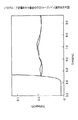
図11は、バスグループ定義を行わない場合のクロストークノイズ波形を示す図である。図11中、縦軸は電圧(V)、横軸は時間(ns)を示す。図11に示すクロストークノイズ波形は、図1に示すノイズ解析対象ネットに対して、図10のステップS35による同方向及び逆方向の伝送方向についてのノイズ解析を行った結果得られるものである。図11からもわかるように、隣接ネットからのクロストークノイズは、最大59mVである。
【0043】
図12は、バスグループ定義を行う場合のクロストークノイズ波形を示す図である。図12中、縦軸は電圧(V)、横軸は時間(ns)を示す。図12に示すクロストークノイズ波形は、図1に示すノイズ解析対象ネットに対して、図10のステップS36による同方向の伝送方向についてのみノイズ解析を行った結果得られるものである。図12からもわかるように、隣接ネットからのクロストークノイズは、最大17mVである。
【0044】
信号の伝送方向が同方向であるバスの場合、逆方向の信号の流れを考慮する必要はない。逆方向の信号の流れによるクロストークノイズは、同一方向の信号の流れによるクロストークノイズより大きいので、逆方向の信号の流れを考慮してしまうと、実際に発生するクロストークノイズよりかなり大きなクロストークノイズが見積もられてしまう。しかし、図12と図11との比較からも明らかなように、本実施例の如く逆方向の信号の流れを考慮する必要がない場合には同方向の伝送方向についてのみノイズ解析を行うことで、正確なクロストークノイズを見積もることができる。
【0045】
尚、構想設計システムや回路エントリシステムと連携する場合には、仮想配線されたデータに基いて、上記実施例と同様の処理を行えば良い。
【0046】
本発明は、以下に付記する発明をも包含するものである。
【0047】
(付記1) 信号の伝送方向が同方向であるバスと、逆方向であるバスとが区別された回路データに基いて、信号の伝送方向が同方向であるバスについては、同方向についてのみクロストークノイズの解析を行うステップを含むことを特徴とする、ノイズ解析方法。
【0048】
(付記2) 前記信号の伝送方向が同方向であるバスは、グループ化されてバスグループ定義ファイルとして管理され、該バスグループ定義ファイルには、信号の伝送方向が同方向である部品がグループ化されてドライバ/レシーバグループとして含まれていることを特徴とする、(付記1)記載のノイズ解析方法。
(付記3) 複数の回路部分に跨ったノイズ解析を行う場合、接続されるネットを同一バスグループ及び同一ドライバ/レシーバグループとみなすステップを含む、(付記2)記載のノイズ解析方法。
【0049】
(付記4) 前記信号の伝送方向が同方向であるバスを指定するステップを含むことを特徴とする、(付記1)〜(付記3)のいずれか1項記載のノイズ解析方法。
【0050】
(付記5) 信号の伝送方向が同方向であるバスと、逆方向であるバスとが区別された回路データに基いて、信号の伝送方向が同方向であるバスについては、同方向についてのみクロストークノイズの解析を行う解析手段を備えたことを特徴とする、ノイズ解析装置。
【0051】
(付記6) 前記信号の伝送方向が同方向であるバスは、グループ化されてバスグループ定義ファイルとして管理する手段を備え、該バスグループ定義ファイルには、信号の伝送方向が同方向である部品がグループ化されてドライバ/レシーバグループとして含まれていることを特徴とする、(付記5)記載のノイズ解析装置。
【0052】
(付記7) コンピュータにノイズ解析機能を持たせるプログラムが格納されたコンピュータ読み取り可能な記憶媒体であって、
該プログラムは、信号の伝送方向が同方向であるバスと、逆方向であるバスとが区別された回路データに基いて、信号の伝送方向が同方向であるバスについては、同方向についてのみクロストークノイズの解析をコンピュータに行わせる解析手順を含むことを特徴とする、記憶媒体。
【0053】
(付記8) 前記プログラムは、前記信号の伝送方向が同方向であるバスは、グループ化されてバスグループ定義ファイルとしてコンピュータに管理させる手順を含み、該バスグループ定義ファイルには、信号の伝送方向が同方向である部品がグループ化されてドライバ/レシーバグループとして含まれていることを特徴とする、(付記7)記載の記憶媒体。
【0054】
(付記9) コンピュータにノイズ解析機能を持たせるコンピュータプログラムであって、
信号の伝送方向が同方向であるバスと、逆方向であるバスとが区別された回路データに基いて、信号の伝送方向が同方向であるバスについては、同方向についてのみクロストークノイズの解析をコンピュータに行わせる解析手順を含むことを特徴とする、コンピュータプログラム。
【0055】
(付記10) 前記信号の伝送方向が同方向であるバスは、グループ化されてバスグループ定義ファイルとしてコンピュータに管理させる手順を含み、該バスグループ定義ファイルには、信号の伝送方向が同方向である部品がグループ化されてドライバ/レシーバグループとして含まれていることを特徴とする、(付記9)記載のコンピュータプログラム。
【0056】
以上、本発明を実施例により説明したが、本発明は上記実施例に限定されるものではなく、本発明の範囲内で種々の変形及び改良が可能であることは、言うまでもない。
【0057】
【発明の効果】
本発明によれば、実際には伝送されない信号の組み合わせについての無駄なノイズ解析を防止してノイズ解析時間を短縮すると共に、正確なノイズ解析結果を得ることのできるノイズ解析方法及び装置、記憶媒体並びにコンピュータプログラムを実現することができる。
【図面の簡単な説明】
【図1】双方向のネットが3本ある場合のノイズ解析を説明するための図である。
【図2】実施例において本発明が適用されるコンピュータシステムを示す斜視図である。
【図3】コンピュータシステムの本体部内の要部の構成を説明するためのブロック図である。
【図4】ドライバ/レシーバグループを説明するための図である。
【図5】複数のLSI,PCB,MCM等に跨ったバスグループ及びドライバ/レシーバグループを説明するための図である。
【図6】ノイズ解析処理を説明するためのフローチャートである。
【図7】バスグループ定義処理を説明するためのフローチャートである。
【図8】バスグループ定義ファイルを説明するための図である。
【図9】ドライバ/レシーバグループ定義処理を説明するためのフローチャートである。
【図10】ノイズ解析処理を説明するためのフローチャートである。
【図11】バスグループ定義を行わない場合のクロストークノイズ波形を示す図である。
【図12】バスグループ定義を行う場合のクロストークノイズ波形を示す図である。
【符号の説明】
100 コンピュータシステム
102 ディスプレイ
103 キーボード
104 マウス
105 モデム
110 ディスク
201 CPU
202 メモリ部
BG1 バスグループ
DRG1,DRG2 ドライバ/レシーバグループ[0001]
BACKGROUND OF THE INVENTION
The present invention relates to a noise analysis method and apparatus, a storage medium, and a computer program. In particular, an electronic circuit such as a large scale integrated circuit (LSI), a multichip module (MCM), a printed circuit board (PCB), and the like is obtained by computer aided design (CAD). Noise analysis method and apparatus for analyzing noise that may occur in an electronic circuit when designing, a computer-readable storage medium storing a computer program for causing a computer to perform such noise analysis, and such a computer program About.
[0002]
In recent years, with the miniaturization and speeding up of various electronic circuits, noise analysis when designing electronic circuits has become important. Noise generated in an electronic circuit is required to be analyzed accurately and at high speed.
[0003]
[Prior art]
Conventionally, various noise analysis tools for performing noise analysis when designing an electronic circuit have been proposed. The noise analysis tool performs noise analysis and noise check using a circuit simulator after the electronic circuit mounting design, and determines noise countermeasures for suppressing noise. The design of the electronic circuit is changed as necessary based on the determined noise countermeasures. After such a design change, noise analysis and noise check are performed again, and the above procedure is repeated until the noise falls within the allowable range.
[0004]
The main noises to consider when designing electronic circuits are reflection noise and crosstalk noise. Usually, the reflected noise is generated due to mismatch between the internal resistance of the driver and the characteristic impedance of the transmission line. On the other hand, the crosstalk noise largely depends on the signal transmission direction, the driving capability of the driver, the gap between adjacent patterns, and the like. Usually, since the analysis of the crosstalk noise requires information of adjacent patterns, the noise analysis and the noise check are performed using the mounting design data after the mounting design of the electronic circuit. Here, the information of adjacent patterns includes a pattern gap, a distance in which the patterns run in parallel, a position where the patterns are parallel on the transmission line, and the like.
However, in the conventional noise analysis method, as described below, the signal transmission direction is not specified when performing bus noise analysis.
[0005]
FIG. 1 is a diagram for explaining noise analysis when there are three bidirectional nets. A net refers to a portion composed of at least one circuit element of interest when designing an electronic circuit. Here, for example, when a transmission signal waveform between the driver / receiver C and the receiver / driver D (hereinafter referred to as “C-D”) is viewed, adjacent nets, that is, between the driver / receiver A and the receiver / driver B (hereinafter referred to as “C-D”). , A-B) and crosstalk noise due to a transmission signal waveform between the driver / receiver E and the receiver / driver F (hereinafter referred to as EF) must be considered.
[0006]
In this case, with respect to the transmission direction of C-> D in (1), crosstalk noise is analyzed between A and B in consideration of the transmission direction of A-> B and the transmission direction of B-> A. Necessary. Also, with respect to the transmission direction of D-> C in (2), the analysis of crosstalk noise is also performed between A and B in consideration of the transmission direction of A-> B and the transmission direction of B-> A. Necessary. Similarly, between E-F, it is necessary to analyze crosstalk noise in consideration of the transmission direction of E-> F and the transmission direction of F-> E.
[0007]
For this reason, when there are many adjacent wirings, a great amount of time is required for noise analysis. In addition, the transmission direction of B-> A and F-> E is opposite to the transmission direction of C-> D with respect to the transmission direction of C-> D. large.
[0008]
[Problems to be solved by the invention]
For example, if the transmission direction is always the same between C-D and EF, there is no F-> E transmission direction with respect to the C-> D transmission direction. In this case, it is useless to perform noise analysis in the transmission direction of F-> E with respect to the transmission direction of C-> D. Such useless noise analysis not only increases the noise analysis time, but also obtains a noise analysis result as if noise larger than the actually generated crosstalk noise is generated.
[0009]
In other words, the conventional noise analysis method does not specify the signal transmission direction when performing bus noise analysis, so noise analysis is performed for combinations of signals that are not actually transmitted for crosstalk noise in bidirectional signals. There was a problem of being done. For this reason, useless noise analysis is performed, noise analysis time increases, and there is a problem that an erroneous noise analysis result is obtained as if noise larger than the actual crosstalk noise is generated. there were.
[0010]
Accordingly, the present invention provides a noise analysis method and apparatus, and a storage medium that can prevent useless noise analysis for a combination of signals that are not actually transmitted to shorten noise analysis time and obtain an accurate noise analysis result. An object of the present invention is to provide a computer program.
[0011]
[Means for Solving the Problems]
The above problem is based on circuit data in which a signal transmission direction is the same as that of a bus in which the signal transmission direction is opposite, and a bus whose signal transmission direction is the same direction is crossed only in the same direction. This can be achieved by a noise analysis method including a step of analyzing talk noise.
[0012]
The above problem is based on circuit data in which the signal transmission direction is the same direction and the bus in which the signal transmission direction is the reverse, and the bus having the same signal transmission direction is only in the same direction. This can also be achieved by a noise analyzing apparatus characterized by including an analyzing means for analyzing crosstalk noise.
[0013]
The above-described problem is a computer-readable storage medium storing a program for causing a computer to have a noise analysis function. The program includes a bus in which the signal transmission direction is the same direction, and a bus in the reverse direction. For a bus whose signal transmission direction is the same based on the circuit data distinguished from each other, a storage medium characterized by including an analysis procedure for causing the computer to analyze the crosstalk noise only in the same direction is also included. Can be achieved.
[0014]
The above-described problem is a computer program for providing a computer with a noise analysis function, in which signal transmission is performed based on circuit data in which a bus having the same signal transmission direction and a bus having the opposite direction are distinguished. A bus having the same direction can also be achieved by a computer program including an analysis procedure for causing a computer to analyze crosstalk noise only in the same direction.
[0015]
Therefore, according to the present invention, a noise analysis method and apparatus that can prevent useless noise analysis for a combination of signals that are not actually transmitted to reduce noise analysis time and obtain an accurate noise analysis result, A storage medium and a computer program can be realized.
[0016]
DETAILED DESCRIPTION OF THE INVENTION
Embodiments of a noise analysis method and apparatus, a storage medium, and a computer program according to the present invention will be described below with reference to the drawings.
[0017]
【Example】
An embodiment of a noise analyzing apparatus according to the present invention will be described. This embodiment of the noise analysis apparatus uses an embodiment of a noise analysis method according to the present invention, an embodiment of a computer-readable storage medium according to the present invention, and an embodiment of a computer program according to the present invention. In this embodiment, the present invention is applied to a computer system. FIG. 2 is a perspective view showing a computer system to which the present invention is applied in this embodiment.
[0018]
A
[0019]
A noise analysis program (or noise analysis software) for causing the
[0020]
FIG. 3 is a block diagram for explaining a configuration of a main part in the
[0021]
The configuration of the
[0022]
First, noise analysis when there are three bidirectional nets will be described with reference to FIG. FIG. 1 is a diagram for explaining noise analysis when there are three bidirectional nets as described above. The noise analysis described in the following description is performed before circuit design, during circuit design, circuit element arrangement, circuit wiring arrangement, and the like.
[0023]
In FIG. 1, first, a bus between CD and a bus between EF are selected and designated as one bus group. The selection of the bus and the designation of the bus group are performed using the
[0024]
Next, noise analysis when a plurality of pins serving as drivers and receivers are connected to one net will be described with reference to FIG. FIG. 4 is a diagram for explaining a driver / receiver group.
[0025]
In FIG. 4, if the transmission directions of the six nets are the same, these six nets are designated as one bus group. In the case of the figure, for example, the bus group BG1 is designated. Also, in the net, a part whose pin is another part is designated on a part basis. At this time, if there are pins of different parts having the same transmission direction, these pins are designated as one driver / receiver group. In the case of the figure, for example, the driver / receiver group DRG1 is designated.
[0026]
For example, when the component PD is selected after the component PB is selected, a message indicating that the selection cannot be made is displayed on the
[0027]
Next, a driver / receiver group is designated with another name for another driver pin. In the case of FIG. 4, for example, the driver / receiver group DRG2 is designated. However, since only one component PD belongs to the driver / receiver group DRG2, the designation of the driver / receiver group DRG2 can be omitted.
[0028]
The noise analysis program first analyzes a pin of a part PA for which no driver / receiver group is specified as a driver. Of the components PA, the signals from the pins specified for the bus group are all analyzed in the same transmission direction. At this time, the pins of the bus group BG1 among the pins of the products PB, PC, and PD are all receivers.
[0029]
Next, when the component PB is a driver, the component PC of the same driver / receiver group DRG1 is also a driver. At this time, of the pins of the parts PA and PD, all the pins belonging to the bus group BG1 are receivers.
[0030]
The component PE is, for example, a damping resistor, and the net is cut here. However, by registering information indicating which pins of the damping resistor and which pins are connected to, for example, a library in the
[0031]
Next, noise analysis for a bus group and a driver / receiver group across a plurality of LSIs, PCBs, MCMs, etc. will be described with reference to FIG. FIG. 5 is a diagram for explaining a bus group and a driver / receiver group straddling a plurality of LSIs, PCBs, MCMs, and the like. In the figure, the same parts as those in FIG.
[0032]
In FIG. 5, the bus group BG1 and the driver / receiver groups DRG1 and DRG2 straddle a plurality of printed circuit boards PCB1 to PCB3. In this case, a bus group and a driver / receiver group are designated for each piece of data on a printed circuit board (PCB). When using a tool for displaying data of a plurality of printed circuit boards (PCBs) at once, a bus group and a driver / receiver group can be specified for a plurality of printed circuit boards (PCBs) at a time. At this time, the bus groups having the same name are handled as one bus group. Also, a driver / receiver group having the same name in one bus group is treated as the same driver / receiver group.
[0033]
For example, when the same PCB is mounted on the motherboard or when the same LSI is mounted on the PCB, the same setting can be adopted for the same LSI by using the same bus group definition file. Also, even if the same PCB or LSI is used, if different bus groups or different driver / receiver groups are used, different bus group definition files are created for each PCB or LSI.
[0034]
FIG. 6 is a flowchart for explaining the noise analysis processing of the
[0035]
In FIG. 6, step S1 performs a circuit input process for inputting information relating to the circuit to be designed. The circuit input process can be performed by operating the
[0036]
In step S3, a placement and routing process for placing circuit elements and placing circuit wiring is performed based on the circuit information and bus information stored in the
In step S4, the wiring data obtained as a result of the wiring arrangement process is stored in a storage unit such as the
[0037]
FIG. 7 is a flowchart for explaining the bus group definition processing. This bus group definition processing is included in the bus group designation processing in step S3A shown in FIG. In FIG. 7, step S <b> 11 selects a net from the circuit displayed on the
[0038]
FIG. 8 is a diagram for explaining the bus group definition file. When the circuit is composed of LSI1 to LSI4, bus group BUS-1, and driver / receiver group DRRV-1 as shown in the figure, the bus group definition file is as follows.
[0039]
HEAD;
PCBNAME PCB-1;
BUS_GROUP BUS-1;
NETNAME A1 A2 A3 A4;
DR_RV_GROUP DRRV-1;
LOCATION LSI2 LSI3;
END;
END;
FIG. 9 is a flowchart for explaining driver / receiver group definition processing. This driver / receiver group definition process is included in the bus group designation process in step S3A shown in FIG. 9, step S21 selects a bus group by designating a bus using the
[0040]
FIG. 10 is a flowchart for explaining the noise analysis processing. This noise analysis process is performed in step S5 shown in FIG. In FIG. 10, step S31 determines an analysis target net. The analysis target net is determined by selecting a net using a
[0041]
On the other hand, if the decision result in the step S33 is NO, a step S34 decides whether or not there is a bus definition in the circuit data. That is, step S34 determines whether there is a bus group definition file. If the decision result in the step S34 is NO, a step S35 performs a noise analysis for the transmission direction in the same direction and the reverse direction on the bus of the analysis target net by a well-known method, and the process returns to the step S32. If the decision result in the step S34 is YES, a step S36 performs a noise analysis only with respect to the same transmission direction based on the bus group definition file and the driver / receiver group definition file, and the process is performed in a step S32. Return to. As a result, step S36 does not perform noise analysis for combinations of transmission directions that do not actually exist, so that the analysis time is shortened and noise larger than the actually generated crosstalk noise is erroneously estimated. Such inconveniences can be prevented.
[0042]
FIG. 11 is a diagram illustrating a crosstalk noise waveform when the bus group definition is not performed. In FIG. 11, the vertical axis represents voltage (V) and the horizontal axis represents time (ns). The crosstalk noise waveform shown in FIG. 11 is obtained as a result of performing noise analysis on the transmission direction in the same direction and the reverse direction in step S35 of FIG. 10 on the noise analysis target net shown in FIG. As can be seen from FIG. 11, the maximum crosstalk noise from the adjacent net is 59 mV.
[0043]
FIG. 12 is a diagram illustrating a crosstalk noise waveform when the bus group definition is performed. In FIG. 12, the vertical axis represents voltage (V) and the horizontal axis represents time (ns). The crosstalk noise waveform shown in FIG. 12 is obtained as a result of performing noise analysis on the noise analysis target net shown in FIG. 1 only in the same transmission direction in step S36 of FIG. As can be seen from FIG. 12, the maximum crosstalk noise from the adjacent net is 17 mV.
[0044]
In the case of a bus in which the signal transmission direction is the same direction, there is no need to consider the reverse signal flow. The crosstalk noise caused by the reverse signal flow is larger than the crosstalk noise caused by the same signal flow. Therefore, if the reverse signal flow is taken into consideration, the crosstalk noise is much larger than the actual crosstalk noise. Talk noise is estimated. However, as is clear from the comparison between FIG. 12 and FIG. 11, when there is no need to consider the flow of signals in the reverse direction as in this embodiment, noise analysis is performed only in the same transmission direction. Accurate crosstalk noise can be estimated.
[0045]
When linking with the concept design system or the circuit entry system, the same processing as in the above embodiment may be performed based on the virtually wired data.
[0046]
The present invention includes the inventions appended below.
[0047]
(Supplementary note 1) Based on circuit data in which a signal transmission direction is the same direction and a bus in which the signal transmission direction is the opposite direction, a bus having the same signal transmission direction is crossed only in the same direction. A noise analysis method comprising a step of analyzing talk noise.
[0048]
(Supplementary Note 2) Buses having the same signal transmission direction are grouped and managed as a bus group definition file, and parts having the same signal transmission direction are grouped in the bus group definition file. The noise analysis method according to (Appendix 1), which is included as a driver / receiver group.
(Supplementary Note 3) The noise analysis method according to (Supplementary Note 2), including a step of considering the connected nets as the same bus group and the same driver / receiver group when performing noise analysis across a plurality of circuit portions.
[0049]
(Appendix 4) The noise analysis method according to any one of (Appendix 1) to (Appendix 3), including a step of designating a bus having the same signal transmission direction.
[0050]
(Supplementary Note 5) Based on circuit data in which a signal transmission direction is the same direction and a bus in which the signal transmission direction is the reverse, a bus having the same signal transmission direction is crossed only in the same direction. A noise analysis apparatus comprising analysis means for analyzing talk noise.
[0051]
(Supplementary Note 6) The buses having the same signal transmission direction are grouped and managed as a bus group definition file, and the bus group definition file includes components having the same signal transmission direction. Are grouped and included as a driver / receiver group. The noise analysis apparatus according to (Appendix 5),
[0052]
(Supplementary note 7) A computer-readable storage medium storing a program for giving a computer a noise analysis function,
The program crosses only the same direction for buses with the same signal transmission direction based on circuit data in which the buses with the same signal transmission direction and the buses with the opposite direction are distinguished. A storage medium comprising an analysis procedure for causing a computer to perform talk noise analysis.
[0053]
(Supplementary Note 8) The program includes a procedure in which buses having the same signal transmission direction are grouped and managed by a computer as a bus group definition file. The bus group definition file includes a signal transmission direction. The storage medium according to (Appendix 7), wherein components having the same direction are grouped and included as a driver / receiver group.
[0054]
(Supplementary note 9) A computer program for giving a computer a noise analysis function,
Based on the circuit data in which the signal transmission direction is the same as the bus in the opposite direction, the bus with the same signal transmission direction is analyzed for crosstalk noise only in the same direction. The computer program characterized by including the analysis procedure which makes a computer perform.
[0055]
(Supplementary Note 10) Buses having the same signal transmission direction include a procedure of grouping them and managing them as a bus group definition file. The bus group definition file includes a signal transmission direction in the same direction. The computer program according to (Appendix 9), wherein certain parts are grouped and included as a driver / receiver group.
[0056]
Although the present invention has been described with reference to the embodiments, it is needless to say that the present invention is not limited to the above-described embodiments, and various modifications and improvements can be made within the scope of the present invention.
[0057]
【The invention's effect】
According to the present invention, a noise analysis method and apparatus and a storage medium capable of preventing noise analysis for a combination of signals that are not actually transmitted to reduce noise analysis time and obtaining an accurate noise analysis result. In addition, a computer program can be realized.
[Brief description of the drawings]
FIG. 1 is a diagram for explaining noise analysis when there are three bidirectional nets.
FIG. 2 is a perspective view showing a computer system to which the present invention is applied in the embodiment.
FIG. 3 is a block diagram for explaining a configuration of a main part in a main body of the computer system.
FIG. 4 is a diagram for explaining a driver / receiver group;
FIG. 5 is a diagram for explaining bus groups and driver / receiver groups straddling a plurality of LSIs, PCBs, MCMs, and the like.
FIG. 6 is a flowchart for explaining noise analysis processing;
FIG. 7 is a flowchart for explaining bus group definition processing;
FIG. 8 is a diagram for explaining a bus group definition file.
FIG. 9 is a flowchart for explaining driver / receiver group definition processing;
FIG. 10 is a flowchart for explaining noise analysis processing;
FIG. 11 is a diagram illustrating a crosstalk noise waveform when the bus group definition is not performed.
FIG. 12 is a diagram showing a crosstalk noise waveform when a bus group is defined.
[Explanation of symbols]
100 computer system
102 display
103 keyboard
104 mouse
105 modem
110 disks
201 CPU
202 Memory unit
BG1 bus group
DRG1, DRG2 driver / receiver group
Claims (6)
該信号の伝送方向が同方向であるバスを、入力手段により選択された該回路データ中のネットに基づいてグループ化してバスグループを定義することでバスグループ定義ファイルを作成し、該バスグループ定義ファイルを記憶手段に格納するステップと、
該回路データ及び該記憶手段に格納された該バスグループ定義ファイルに基づいて、信号の伝送方向が同方向であるバスについては、同方向についてのみクロストークノイズの解析を行うステップとを含むことを特徴とする、ノイズ解析方法。A computer-based noise analysis method for analyzing crosstalk noise based on circuit data including a bus in which the signal transmission direction is the same direction and a bus in the opposite direction,
A bus group definition file is created by grouping buses having the same signal transmission direction based on nets in the circuit data selected by the input means and defining a bus group, and defining the bus group definition Storing the file in a storage means;
Based on the stored in the circuit data and said storage means said bus group definition file, the transmission direction of the signal for the bus in the same direction, the including the step of analyzing the crosstalk noise only for the same direction A characteristic noise analysis method.
入力手段と、
記憶手段と、
該信号の伝送方向が同方向であるバスを、該入力手段により選択された該回路データ中のネットに基づいてグループ化してバスグループを定義することでバスグループ定義ファイルを作成し、該バスグループ定義ファイルを該記憶手段に格納する手段と、
該回路データ及び該記憶手段に格納された該バスグループ定義ファイルに基づいて、信号の伝送方向が同方向であるバスについては、同方向についてのみクロストークノイズの解析を行う解析手段を備えたことを特徴とする、ノイズ解析装置。A noise analysis device for analyzing crosstalk noise based on circuit data including a bus in which the signal transmission direction is the same direction and a bus in the opposite direction ,
Input means;
Storage means;
A bus group definition file is created by grouping buses having the same signal transmission direction based on a net in the circuit data selected by the input means and defining a bus group, and generating the bus group definition file Means for storing a definition file in the storage means;
Based on the circuit data and the bus group definition file stored in the storage means, for a bus whose signal transmission direction is the same direction, an analysis means for analyzing crosstalk noise only in the same direction is provided. A noise analyzer.
該コンピュータに、該信号の伝送方向が同方向であるバスを、入力手段により選択されたネットに基づいてグループ化してバスグループを定義することでバスグループ定義ファイルを作成させ、該バスグループ定義ファイルを記憶手段に格納させる手順と、 Causing the computer to create a bus group definition file by grouping buses having the same signal transmission direction based on the net selected by the input means and defining the bus group; Storing the data in the storage means;
該コンピュータに、該回路データ及び該記憶手段に格納された該バスグループ定義ファイルに基づいて、信号の伝送方向が同方向であるバスについては、同方向についてのみクロストークノイズの解析を行わせる解析手順を含むことを特徴とする、記憶媒体。 Analysis that causes the computer to analyze crosstalk noise only in the same direction for a bus having the same signal transmission direction based on the circuit data and the bus group definition file stored in the storage means A storage medium comprising a procedure.
該コンピュータに、該信号の伝送方向が同方向であるバスを、入力手段により選択されたネットに基づいてグループ化してバスグループを定義することでバスグループ定義ファイルを作成させ、該バスグループ定義ファイルを記憶手段に格納させる手順と、 Causing the computer to create a bus group definition file by grouping buses having the same signal transmission direction based on the net selected by the input means and defining the bus group; Storing the data in the storage means;
該コンピュータに、該回路データ及び該記憶手段に格納された該バスグループ定義ファイルに基づいて、信号の伝送方向が同方向であるバスについては、同方向についてのみクロストークノイズの解析を行わせる解析手順を含むことを特徴とする、コンピュータプログラム。 Analysis that causes the computer to analyze crosstalk noise only in the same direction for a bus having the same signal transmission direction based on the circuit data and the bus group definition file stored in the storage means A computer program comprising a procedure.
Priority Applications (1)
| Application Number | Priority Date | Filing Date | Title |
|---|---|---|---|
| JP2001168752A JP3961786B2 (en) | 2000-06-05 | 2001-06-04 | Noise analysis method and apparatus, storage medium, and computer program |
Applications Claiming Priority (3)
| Application Number | Priority Date | Filing Date | Title |
|---|---|---|---|
| JP2000-167647 | 2000-06-05 | ||
| JP2000167647 | 2000-06-05 | ||
| JP2001168752A JP3961786B2 (en) | 2000-06-05 | 2001-06-04 | Noise analysis method and apparatus, storage medium, and computer program |
Publications (2)
| Publication Number | Publication Date |
|---|---|
| JP2002063227A JP2002063227A (en) | 2002-02-28 |
| JP3961786B2 true JP3961786B2 (en) | 2007-08-22 |
Family
ID=26593323
Family Applications (1)
| Application Number | Title | Priority Date | Filing Date |
|---|---|---|---|
| JP2001168752A Expired - Fee Related JP3961786B2 (en) | 2000-06-05 | 2001-06-04 | Noise analysis method and apparatus, storage medium, and computer program |
Country Status (1)
| Country | Link |
|---|---|
| JP (1) | JP3961786B2 (en) |
Families Citing this family (4)
| Publication number | Priority date | Publication date | Assignee | Title |
|---|---|---|---|---|
| KR100448715B1 (en) * | 2002-06-10 | 2004-09-13 | 삼성전자주식회사 | aggressor classification method for analyzing crosstalk of circuit |
| JP5239648B2 (en) * | 2008-09-01 | 2013-07-17 | 富士通株式会社 | Signal transmission system evaluation apparatus, signal transmission system evaluation program, and signal transmission system design method |
| JP5407226B2 (en) * | 2008-09-01 | 2014-02-05 | 富士通株式会社 | Signal transmission system evaluation apparatus, signal transmission system evaluation program, and signal transmission system design method |
| CN116915284A (en) * | 2023-06-06 | 2023-10-20 | 曙光信息产业(北京)有限公司 | Anti-crosstalk performance test methods, devices, systems, equipment and storage media |
-
2001
- 2001-06-04 JP JP2001168752A patent/JP3961786B2/en not_active Expired - Fee Related
Also Published As
| Publication number | Publication date |
|---|---|
| JP2002063227A (en) | 2002-02-28 |
Similar Documents
| Publication | Publication Date | Title |
|---|---|---|
| JP3264806B2 (en) | Circuit simulation model extraction method and apparatus | |
| US7398497B2 (en) | Electronic circuit designing method apparatus for designing an electronic circuit, and storage medium for storing an electronic circuit designing method | |
| US6915249B1 (en) | Noise checking method and apparatus | |
| US6769102B2 (en) | Verifying proximity of ground metal to signal traces in an integrated circuit | |
| KR100952882B1 (en) | Computer-readable recording media recording a combo check support device and a combo check support program | |
| US20010044709A1 (en) | Noise countermeasure determination method and apparatus and storage medium | |
| JP3655106B2 (en) | Noise check device | |
| US20030074638A1 (en) | Design support apparatus for circuit including directional coupler, design support tool, method of designing circuit, and circuit board | |
| US20030084412A1 (en) | Automated crosstalk identification system | |
| JP6636968B2 (en) | Printed circuit board measurement point setting system, measurement point setting method and measurement point setting program | |
| JP5071081B2 (en) | Simultaneous operation signal noise basic characteristic acquisition method and program in simultaneous operation signal noise estimation method for semiconductor device | |
| JP2002063227A (en) | Noise analysis method and apparatus, storage medium, and computer program | |
| US6662132B2 (en) | Noise analyzing method and apparatus and storage medium | |
| US20080109773A1 (en) | Analyzing Impedance Discontinuities In A Printed Circuit Board | |
| JP3991224B2 (en) | Card design verification method and card design verification system | |
| JPH09274623A (en) | Transmission line simulation system and transmission line simulation method using the same | |
| JP4544118B2 (en) | Circuit verification system and method, and program | |
| US20010041970A1 (en) | Noise countermeasure determination method and apparatus and storage medium | |
| JP3598201B2 (en) | WIRING APPARATUS, WIRING METHOD, AND COMPUTER-READABLE RECORDING MEDIUM RECORDING WIRING PROGRAM | |
| EP4485269A1 (en) | Method for performing automatic layout defect checking control regarding circuit design, associated apparatus and associated computer-readable medium | |
| US20070198173A1 (en) | Return route search device, circuit design apparatus and circuit design program storage medium | |
| JP4781994B2 (en) | Signal waveform analyzer | |
| JP2005100171A (en) | Countermeasure circuit diagram creation apparatus, electronic circuit board design apparatus, countermeasure circuit diagram creation method, countermeasure circuit diagram creation program, and recording medium recording the program | |
| JP2000207438A (en) | Printed wiring board design support equipment | |
| JP3716747B2 (en) | Connection pin number correspondence data generation system |
Legal Events
| Date | Code | Title | Description |
|---|---|---|---|
| A131 | Notification of reasons for refusal |
Free format text: JAPANESE INTERMEDIATE CODE: A131 Effective date: 20070109 |
|
| A521 | Written amendment |
Free format text: JAPANESE INTERMEDIATE CODE: A523 Effective date: 20070309 |
|
| TRDD | Decision of grant or rejection written | ||
| A01 | Written decision to grant a patent or to grant a registration (utility model) |
Free format text: JAPANESE INTERMEDIATE CODE: A01 Effective date: 20070424 |
|
| A61 | First payment of annual fees (during grant procedure) |
Free format text: JAPANESE INTERMEDIATE CODE: A61 Effective date: 20070517 |
|
| R150 | Certificate of patent or registration of utility model |
Free format text: JAPANESE INTERMEDIATE CODE: R150 |
|
| FPAY | Renewal fee payment (event date is renewal date of database) |
Free format text: PAYMENT UNTIL: 20100525 Year of fee payment: 3 |
|
| FPAY | Renewal fee payment (event date is renewal date of database) |
Free format text: PAYMENT UNTIL: 20110525 Year of fee payment: 4 |
|
| FPAY | Renewal fee payment (event date is renewal date of database) |
Free format text: PAYMENT UNTIL: 20120525 Year of fee payment: 5 |
|
| FPAY | Renewal fee payment (event date is renewal date of database) |
Free format text: PAYMENT UNTIL: 20130525 Year of fee payment: 6 |
|
| FPAY | Renewal fee payment (event date is renewal date of database) |
Free format text: PAYMENT UNTIL: 20140525 Year of fee payment: 7 |
|
| LAPS | Cancellation because of no payment of annual fees |