JP3992766B2 - Computer-assisted video microscope - Google Patents
Computer-assisted video microscope Download PDFInfo
- Publication number
- JP3992766B2 JP3992766B2 JP06519196A JP6519196A JP3992766B2 JP 3992766 B2 JP3992766 B2 JP 3992766B2 JP 06519196 A JP06519196 A JP 06519196A JP 6519196 A JP6519196 A JP 6519196A JP 3992766 B2 JP3992766 B2 JP 3992766B2
- Authority
- JP
- Japan
- Prior art keywords
- microscope
- plane
- preparation
- computer
- video
- Prior art date
- Legal status (The legal status is an assumption and is not a legal conclusion. Google has not performed a legal analysis and makes no representation as to the accuracy of the status listed.)
- Expired - Lifetime
Links
- 238000002360 preparation method Methods 0.000 claims description 51
- 230000003287 optical effect Effects 0.000 claims description 44
- 238000005286 illumination Methods 0.000 claims description 26
- 238000004590 computer program Methods 0.000 claims description 3
- 238000003780 insertion Methods 0.000 description 19
- 230000037431 insertion Effects 0.000 description 19
- 230000007246 mechanism Effects 0.000 description 15
- 238000000034 method Methods 0.000 description 6
- 230000002093 peripheral effect Effects 0.000 description 5
- 238000012545 processing Methods 0.000 description 4
- 230000006870 function Effects 0.000 description 3
- 241000276498 Pollachius virens Species 0.000 description 2
- 230000008859 change Effects 0.000 description 2
- 210000000078 claw Anatomy 0.000 description 2
- 238000010586 diagram Methods 0.000 description 2
- 238000012015 optical character recognition Methods 0.000 description 2
- 239000000758 substrate Substances 0.000 description 2
- 230000007723 transport mechanism Effects 0.000 description 2
- 230000002411 adverse Effects 0.000 description 1
- 230000004888 barrier function Effects 0.000 description 1
- 230000005540 biological transmission Effects 0.000 description 1
- 230000015572 biosynthetic process Effects 0.000 description 1
- 238000004891 communication Methods 0.000 description 1
- 230000001419 dependent effect Effects 0.000 description 1
- 230000005611 electricity Effects 0.000 description 1
- 239000011888 foil Substances 0.000 description 1
- 239000011521 glass Substances 0.000 description 1
- 239000002241 glass-ceramic Substances 0.000 description 1
- 238000003384 imaging method Methods 0.000 description 1
- 230000003993 interaction Effects 0.000 description 1
- 238000001000 micrograph Methods 0.000 description 1
- 238000012544 monitoring process Methods 0.000 description 1
- 230000001575 pathological effect Effects 0.000 description 1
- 230000008569 process Effects 0.000 description 1
- 239000003190 viscoelastic substance Substances 0.000 description 1
Images


Classifications
-
- H—ELECTRICITY
- H04—ELECTRIC COMMUNICATION TECHNIQUE
- H04N—PICTORIAL COMMUNICATION, e.g. TELEVISION
- H04N7/00—Television systems
- H04N7/18—Closed-circuit television [CCTV] systems, i.e. systems in which the video signal is not broadcast
- H04N7/183—Closed-circuit television [CCTV] systems, i.e. systems in which the video signal is not broadcast for receiving images from a single remote source
-
- G—PHYSICS
- G02—OPTICS
- G02B—OPTICAL ELEMENTS, SYSTEMS OR APPARATUS
- G02B21/00—Microscopes
- G02B21/36—Microscopes arranged for photographic purposes or projection purposes or digital imaging or video purposes including associated control and data processing arrangements
- G02B21/361—Optical details, e.g. image relay to the camera or image sensor
-
- G—PHYSICS
- G02—OPTICS
- G02B—OPTICAL ELEMENTS, SYSTEMS OR APPARATUS
- G02B21/00—Microscopes
- G02B21/36—Microscopes arranged for photographic purposes or projection purposes or digital imaging or video purposes including associated control and data processing arrangements
- G02B21/362—Mechanical details, e.g. mountings for the camera or image sensor, housings
-
- G—PHYSICS
- G02—OPTICS
- G02B—OPTICAL ELEMENTS, SYSTEMS OR APPARATUS
- G02B21/00—Microscopes
- G02B21/36—Microscopes arranged for photographic purposes or projection purposes or digital imaging or video purposes including associated control and data processing arrangements
- G02B21/365—Control or image processing arrangements for digital or video microscopes
Landscapes
- Physics & Mathematics (AREA)
- Engineering & Computer Science (AREA)
- Multimedia (AREA)
- Chemical & Material Sciences (AREA)
- Analytical Chemistry (AREA)
- General Physics & Mathematics (AREA)
- Optics & Photonics (AREA)
- Computer Vision & Pattern Recognition (AREA)
- Signal Processing (AREA)
- Microscoopes, Condenser (AREA)
Description
【0001】
【発明の属する技術分野】
本発明はコンピュータ支援顕微鏡装置に関する。
【0002】
【従来の技術】
出願人の米国特許第5,031,099号からは、従来通りの顕微鏡スタンドを有する顕微鏡と、それとは別個に配置されるコンピュータと、コンピュータに付属するモニタ、プリンタ、キーボードなどの周辺装置とから構成されるコンピュータ支援ビデオ顕微鏡が知られている。この場合、コンピュータは、周辺装置との通信を可能にすると共に、電動焦点合わせ動作や電動十字マークなどの顕微鏡の様々に異なる電動機能の制御をも可能にする多種多様な差し込みカードを含む。このように一体化されていない構造を利用する方法においては、顕微鏡の装置全体のみならず、モニタ、キーボードなどのコンピュータの周辺装置及び場合によってはコンピュータマウス又はトラックボールのような他の入力手段をもワークテーブル上に並べて配置しなければならないので、きわめて広いスペースを必要とするという欠点がある。
【0003】
さらに、英国特許第2084754号により知られているモジュール構成の顕微鏡は複数の挿入口を有するフレームから構成され、照明モジュールと観察モジュールをこのフレームの異なる口に差し込むことができる。この顕微鏡では、必要に応じて、同一の光学素子を利用して直立顕微鏡又は倒立顕微鏡を選択的に実現することができる。さらに、この場合、後の画像処理に備えてビデオ出力端子を介してビデオカメラを接続できることも記載されている。ところが、このシステムで要求されるスペースは少なくとも上記の米国特許による顕微鏡と同じ程度には大きい。
【0004】
さらに、米国特許第4,361,377号には、密閉ハウジングを有し且つ観察時には顕微鏡用プレパラートをハウジングの開口を経てハウジングの内部へ挿入することができる単眼小型顕微鏡が記載されている。ところが、この場合の最も単純な顕微鏡においては、画像記録又は画像処理などのコンピュータ支援は不可能である。
【0005】
【発明が解決しようとする課題】
本発明は、コンパクトな構造を有し且つ顕微操作者のワークステーションでごくわずかしかスペースを必要としない特に臨床ルーチン検査又は病理ルーチン検査のためのコンピュータ支援ビデオ顕微鏡を提供すべきである。
【0006】
【課題を解決するための手段】
この目的は、独立特許請求の範囲第1項及び第2項の特徴を伴う顕微鏡によって解決される。本発明の有利な構成は従属特許請求の範囲の特徴から明らかである。
【0007】
すなわち、本発明によるビデオ顕微鏡は密閉ハウジングを有し、そのハウジングの中に顕微鏡の全ての光学素子が配置されている。ハウジングの前面は、標準形の被検体支持体の上に顕微鏡用プレパラートを導入するための開口をさらに有する。従って、本発明によれば、対物レンズ、集光レンズ及び被検体載置台を任意に操作できるこれまでと変わらない通常通りの顕微鏡構成ではない。ユーザが依然として操作できるのは、プレパラートを挿入するための開口スリットと、場合によっては、顕微鏡用プレパラートの照明に利用されるランプが損傷した場合にランプを交換するときに使用するランプ交換口のみである。そこで、ビデオモニタを顕微鏡の上に設置できるように、本発明によるビデオ顕微鏡のハウジングを特に直方体形に形成することができる。ハウジングの外寸は市販のディスケットメカニズム又はコンパクトディスクメカニズムの寸法に相応しているので、それに合わせて準備されているネットワーク一体型の標準ハウジングを使用できる。従って、顕微鏡とそのようなメカニズムを互いに積み重ねるか又は複数の顕微鏡を互いに積み重ねることも可能であり、その結果、顕微鏡操作者のワークテーブル上に顕微鏡を設置するために付加スペースが要求されることはほぼない。
【0008】
別の実施の態様においては、顕微鏡はパーソナルコンピュータのディスクメカニズム受け入れ口に挿入するための構成を有する。この場合、顕微鏡は5 1/4ツォルの標準受け入れ口寸法のうちわずか1つ分又は2つ分のスペースを占めるだけであるのが好ましい。そのため、いわゆるラック構造のコンピュータでは、空いたディスクメカニズム受け入れ口の未使用スペースを利用することになる。さらに、コンピュータのネットワーク部を顕微鏡の電流供給にも同時に使用できるので、顕微鏡専用の追加ネットワーク部を設けなくとも良い。
【0009】
2つの実施の態様においては、被検体平面が水平に向いているとき、顕微鏡の水平方向寸法は垂直方向寸法より大きい。この点で、本発明による顕微鏡の外観は従来の顕微鏡構成とは全く異なっている。
【0010】
プレパラートの挿入を除き、顕微鏡全体の制御は、双方の実施の態様に共通して、たとえば、キーボード、マウス、トラックボール又はトラックパッドなどのコンピュータの入力手段を介して実行される。従って、顕微鏡の内部にある可動光学素子及び可動機械要素は全て電動駆動されている。そこで、電動運動を制御するための電子素子は顕微鏡の外のドライバカード、たとえば、コンピュータの差し込みカードに配置されるべきであろう。これにより、ドライバカードから発生する熱は顕微鏡から離れた場所に保持されるので、光路に悪影響を及ぼす可能性のある顕微鏡内部の熱膨張が引起こされるおそれはない。ドライバカードと顕微鏡はデジタルデータ経路、たとえば、コンピュータバスを介して互いに接続されている。
【0011】
特にコンパクトな構造を得るためには、顕微鏡の中で光線をほぼZ形に導くと有利である。その場合、光源から発出した光は、まず、第1の平面、すなわち、照明平面に位置する光路に沿って導かれ、顕微鏡のほぼ中央でミラーにより照明平面に対しほぼ垂直な方向へ方向転換され、プレパラートを通過した後、第2のミラーにより第2の、第1の平面と平行な観察平面に位置する光軸に沿って方向転換され、続いて、この第2の平面においてビデオセンサへと導かれる。照明平面と観察平面の双方で十分に長い光路を実現するために、それぞれの平面にある光路をさらに折ることができる。照明平面及び観察平面と平行なさらに別の第3の平面には、被検体載置台として、ハウジングの挿入口と整列する支持面を設けるべきであろう。
【0012】
プレパラートを動かして被検体の関心部分を選択するために、2つの互いに垂直な方向に移動自在なピンセット状のマニピュレータを設けることができる。プレパラートを挿入したとき、このマニピュレータは所定の引渡し位置でプレパラートをつかみ、続いてプレパラートを支持面に沿ってすべらせながら所望の位置へ導く。
【0013】
コンパクトな構造であり、その結果として変換自在の対物レンズを使用しないにもかかわらず、様々に異なる倍率を得ることができるようにするためには、顕微鏡対物レンズを複数の部分から構成し、対物レンズの前方レンズ又は前方レンズ群を含む前部を電動方式で光路に対し出し入れ自在にするべきであろう。さらに、対物レンズの少なくとも第2の部分素子を焦点合わせのために光軸と平行に電動方式で摺動自在にすべきであろう。
【0014】
本発明による顕微鏡においては、顕微鏡の中に挿入されたプレパラートに手を触れることはできず、そのため、プレパラートで向きを設定することは不可能であるので、ハウジングの内部の、開口の付近に、アレイセンサを配置すべきであろう。プレパラートを挿入するとき、プレパラートはアレイセンサの前方を通過する。これにより、プレパラートのおおまかな概観像を形成し、向きを確定するためにその画像をモニタに表示することができる。同時に、場合によっては、被検体支持体上にあるバーコードをダイオードセルによって走査することができ、そのバーコードの中にコード化されている情報をコンピュータのメモリに直接に書込むことが可能である。バーコードの代わりに又はバーコードに加えて、プレパラート支持体に記入された文字を必要に応じてOCR(光学文字認識)画像処理用ソフトウェアによって認識し、対応するASCII文字の形態でコンピュータのデータバンクに書込むこともできる。
次に、図に示されている実施形態に基づいて本発明の個々の点をさらに詳細に説明する。
【0015】
【発明の実施の形態】
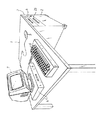
図1の斜視図において1は顕微鏡操作者のワークテーブルである。テーブル1の下方にはパーソナルコンピュータ3のラック2(直立している)が配置されている。顕微鏡4は利用可能なコンピュータラック2のディスクメカニズム受け入れ口の1つに挿入される。その他のディスクメカニズム受け入れ口は空いていても良く、あるいは、同じ構造又は類似する構造の別の顕微鏡(図示せず)又は図4に示唆するようなフロッピーディスクメカニズムやCDメカニズムなどのディスクメカニズム37,38を収納していても良い。挿入口25へのプレパラートの出入れを除いて、顕微鏡4の操作はコンピュータのコンピュータマウス5及びキーボード6によって実行される。ビデオモニタ7は顕微鏡の画像を表示する。
【0016】
本発明による顕微鏡4はコンパクトな構造であるために、ワークステーション1のテーブル面で全くスペースをとらないので、ワークステーションには、コンピュータ操作のために必要な周辺装置のみが設置されている。また、たとえば、全てのディスクメカニズム受け入れ口が使用中であるか又はラック構成のコンピュータの代わりにいわゆるデスクトップコンピュータを使用するために、コンピュータラック2の中に利用可能なディスクメカニズム受け入れ口がない場合であっても、本発明による別の構造の顕微鏡4′をビデオモニタ7の下方に配置することができる。顕微鏡4′は外部ディスクメカニズム向けの標準形ハウジングと、コンピュータのドライバカードに至る追加の接続ケーブルとを有する。デスクトップコンピュータの場合、コンピュータと、顕微鏡4′と、場合によっては1つ又は複数のディスクメカニズムと、モニタ7とを積み重ねることができる。顕微鏡4′は概念の上では差し込み装置としてではなく、付属装置として構成されているのであるが、以下にさらに詳細に説明する顕微鏡4とほぼ同じ構造を有する。唯一の相違点は、顕微鏡4′が別個のネットワーク部(図示せず)を有し、顕微鏡4とは異なり、コンピュータ3の高速PCバスに接続されるのではなく、コンピュータ3の接続カードに接続されるということである。
【0017】
図4のブロック線図には、コンピュータラック2が点線で表示されている。ラック2の中にはコンピュータ3と、複数のディスクメカニズム37,38と、顕微鏡4とが配置され、それらは高速PCバス35、たとえば、32ビットのデータ幅をもつバスを介して接続している。顕微鏡4に電流を供給する働きをするのはコンピュータネットワーク部39である。顕微鏡を制御するために、コンピュータ3にはドライバカード40が設けられており、顕微鏡4の様々なモータを制御するための電子素子はそのドライバカードに配置されている。顕微鏡4はドライバカード40を介して、コンピュータ3の作業用メモリにロードされているプログラム42に応じて制御される。複数の接続カード41を介して、コンピュータ3は周知のようにモニタ7、キーボード6及びマウス5のような周辺装置と接続している。
【0018】
図2及び図3からわかるように、顕微鏡4はほぼ直方体形のハウジング8を有し、そのハウジングの中に顕微鏡の光学素子と機械要素が全て配置されている。この場合、詳細には示されていないが、ハウジング8は、通常通り、2つ又は3つの、ねじ結合などの手段により互いに結合された部分から構成されている。ハウジングの唯一つの開口はプレパラートの挿入口として利用される水平のスリット25であり、ハウジング8の前面8aにある。さらに、ランプ10を交換するときのために、挿入口25の隣には前面8aから取り外し自在に蓋部分31が設けられている。
【0019】
光線の誘導は、それぞれの光学素子の光軸により決められている通りに、顕微鏡の内部で2つの異なる平面において行われる。それらの平面のうち一方は観察平面であり、図2の切断平面と一致する。第2の平面は照明平面であり、図2の図面の平面の下側に位置している。照明平面と観察平面は互いに平行である。
【0020】
照明平面及び観察平面に加えて、同様にそれら2つの平面と平行に位置する第3の平面がある。これは、ガラス又はガラスセラミックから製造された透明板33の表面によって形成され且つ挿入口25と同じ高さに並んでいるプレパラート平面である。
【0021】
顕微鏡の光源10はハウジングの前方領域に、挿入口25の脇に並んで配置されている。光源10から出た照明光路は、まず、顕微鏡の側壁とほぼ平行に後方へ向かい、モータ11aを介して駆動される集光レンズズーム11を通過する。なお、ハウジングの前方とは図2の左側で後方とは右側である。集光レンズズーム11は照射野を微調整する働きをする。集光レンズズーム11を通過した後、照明光路はミラー12により照明平面の中で斜め前方へ反射され、次に、2分割集光レンズの第1の部分13を通過する。その後に続くミラー15を経て照明光路は照明平面に対し垂直に上方へ偏向され、プレパラート平面の前で、集光レンズの第2の部分16を通過する。集光レンズの2つの部分(13,16)は複数のレンズ又はレンズ群を含んでいて良いが、図では簡易にするために単独のレンズとして示されている。直径の異なる複数の開口と、リング形ダイアフラムと、DICプリズムとを有する電動ダイアフラムスライダ14を介して、照明光路の口径及び/又は所望のコントラストを調整可能である。特に照射野の大きい照明を得るために、さらに、集光レンズの第2の部分16も同様に電動方式で光路からはずすことができるように構成されている。ダイアフラムスライダ14により口径を調整すると共に、集光レンズズーム11によって照射野を調整することにより、本発明による顕微鏡においても、ケーラー照明を実現できる。
【0022】
観察側の光学素子の配列は、ほぼ照明光路の光軸とプレパラート平面との交点で、照明光路に対し点対称である。従って、対物レンズの前部17の光学素子は集光レンズの第2の部分16と同軸に配置されており、同様に小さな倍率での結像のために電動方式で光路からはずすことができるように構成されている。対物レンズの前部17の後方では、垂直方向に進む光路は別のミラー18を経て、照明光路と平行な観察平面へと方向転換され、続いて対物レンズの第2の部分20を通過する。集光レンズ13,16の場合と同様に、対物レンズの2つの部分17,20も複数のレンズ又はレンズ群を含んでいて良いのであるが、簡易にするために単独のレンズとして図示されている。光路は後続するミラー21を経て観察平面で後方へ偏向され、モータ22aを介して駆動される観察側ズーム22の後でビデオチップ23に到達する。
【0023】
たとえば、位相コントラスト又は微分干渉コントラストなどのコントラストを確定する方法として、複数の異なる切替え位置19a,19b(図2には切替え位置は2つしか示されていない)を有する別の電動ダイアフラムスライダ19が観察光路の中に配置されている。特定のコントラスト確定方式と、それに対応するダイアフラムスライダ14の切替え位置を選択するときに、それに付随するコントラスト変調器19a,19bが自動的に光路に導入されるように、ダイアフラムスライダ19の切替え位置はコンピュータプログラムを介して集光レンズダイアフラムスライダ14の切替え位置と結合している。たとえば、位相コントラストの確定が望まれており、それに応じてダイアフラムスライダ14を介してリング形ダイアフラムを光路の中へ導入するのであれば、付随する位相板もダイアフラムスライダ19を介して自動的に観察光路の中へ導入される。微分干渉コントラストについても同様のことが起こるのは自明であり、その場合、照明側と観察側の双方で互いに適合する、適切なDICプリズムと偏光箔が導入されることになる。
【0024】
挿入口25に差し込まれたプレパラートを搬送するために、2つの異なる搬送機構が設けられている。第1の搬送機構はプレパラート引込み装置26から構成されており、この引込み装置は、たとえば、挿入口25のすぐ後ろで、プレパラート平面の上側に配置され、電動駆動される駆動ローラから形成されていれば良い。プレパラートは引込み装置26により顕微鏡の内部へ引込まれる。続いて、引き渡し位置でプレパラートはピンセット形のマニピュレータ29,29a,29bによって把持され、マニピュレータの2つのつめ29a,29bでしっかりとクランプされる。2つのつかみつめ29a,29bのクランプ運動は電磁石(図示せず)又はばね力により行われる。マニピュレータ29,29a,29bはプレパラート平面と平行に、2つの互いに垂直な方向へ移動自在である。この移動のために、まず、マニピュレータ29,29a,29b自体をラック28に沿って案内し、そのラック28をラック28に対しそれぞれ垂直に位置する2本の互いに平行なロッド27a,27bによって案内する。この場合、2本の平行なロッドの一方27aは、マニピュレータ29を挿入口25の方向へ移動させるためにハウジングに配置されたモータ27cにより駆動されて、回転運動するラックとして構成されている。その方向に対し垂直な方向への駆動のためには、マニピュレータ29自体に別のマイクロモータ34が設けられている。
【0025】
ここで、図2及び図3においては光学素子と電動駆動要素は示されているが、図を見やすくするために、それらとバス差し込みプラグ24との間の接続線路は図示されていないということを明示しておく。コンピュータ3と顕微鏡との接続は、全て、顕微鏡をPCバス35(図4を参照)に接続する差し込みプラグ24を介して行われる。従って、プラグ24はデータ入出力部として動作する。
【0026】
挿入口25を監視するために、挿入口のすぐ背後にダイオードアレイ32が配置されている。このダイオードアレイ32は挿入口を監視すると同時に、プレパラートの概観像を形成する働きもする。プレパラートを被検体支持体30に載せて挿入口25に差し込むと、ダイオードアレイ32はそのアレイに入射するランプ10の光の強さの変化を検出する。あるいは、ダイオードアレイを追加の発光ダイオードと組合わせて、挿入口に光のバリヤを形成することも可能である。そこで、ダイオードアレイ32の出力信号はプレパラート引込み装置26をオンするトリガパルスを発生させる。発光ダイオードを追加する実施形態の場合には、トリガパルスはランプ10それ自体をもオンすることができる。引込み中、プレパラート支持体30はダイオードアレイの下方を通過し、その際に接触方式でプレパラート30の概観像を走査撮影し、続いてモニタに表示する。この概観像を作成するときの照明を得るために、光源10から拡散発出する光の一部を利用する。プレパラートにバーコード又は文字が設けられていれば、その後の概観像の画像処理によってその画像に含まれている情報を復号し、プレパラートに対応するコンピュータ3のデータバンクに書込む。被検体支持体30が顕微鏡の内部へ全て引込まれた後、引込み装置26は動作停止し、被検体支持体30はマニピュレータ29,29a,29bによってつかまれる。続いて、マウス5又はトラックボール(図示せず)を使用して、モニタ7上のコンピュータカーソルを所望の被検体部分に位置決めする。マニピュレータ29,29a,29bの駆動装置27c,34を介して、被検体支持体30はコンピュータカーソルの位置に応じて摺動するが、この摺動は、コンピュータカーソルにより選択された概観像の中の位置が光軸とプレパラート平面の交点と常に一致するように行われる。従来の顕微鏡で後に検査するときにも、プレパラートの関心領域を台のバーニャを利用して容易に再び見つけることができるように、その関心領域の座標を読取り、記憶できる。
【0027】
所望のコントラスト設定と所望の倍率はコンピュータキーボード6を介して調整可能である。所望の倍率に応じて、対物レンズの前部レンズ17は光路に出入りするように旋回され、且つ観察側ズーム22は駆動モータ22aを介して調整される。集光レンズの第2の部分16や集光レンズズーム11のような照明側素子は、プログラム制御により、ケーラー照明に設定される。たとえば、冒頭で挙げた米国特許第5,031,099号の中でも実現されているような受動オートフォーカスという意味での焦点合わせを実行するために、対物レンズの第2の部分20は光軸と平行に、ビデオチップ23によって記録される画像が最大コントラストに達するまで摺動される。さらに、その後、たとえば、コントラストの弱い画像部分に焦点合わせするために、マウスを介して又はコンピュータキーボードの方向キーを使用して手動操作で焦点合わせをすることができる。
【0028】
プレパラートを十分に検査し終わり、それ以上の検査が望まれない場合には、マニピュレータ29,29a,29bによって被検体支持体30を先にマニピュレータがプレパラートをつかんでいた引き渡し位置に再び戻し、続いて、引込み装置26により再び挿入口25を通して顕微鏡の外へ排出する。その後、別のプレパラートが挿入されるのに備えて、ダイオードアレイ32は挿入口25を監視する。
【0029】
図2及び図3に示した本発明による顕微鏡の構造全体の幅は140mm、奥行は170mm、高さは40mm又は80mmである。プレパラート30を移動させるためのマニピュレータ29の自由運動経路の長さは顕微鏡の奥行方向に75mmを越え、顕微鏡の幅方向には25mmを越える。これにより、対物レンズの前部レンズと集光レンズとの間に、従来の被検体支持体のあらゆる位置を設定することができる。光線の誘導経路をできる限りコンパクトに形成するように、カメラチップ23の対角線の長さは多くとも1/2インチであり、相応して小さい像領域を得るために顕微鏡内部の光学系全体も設計されている。その結果、使用される結像光学系の交差距離は(像領域の直径が約20mmの場合の)従来の光学系の交差距離の約30%から50%まで短くなり、これはコンパクトな構造を得るには非常に有利である。
【0030】
ランプの輝度は、カメラチップ23によって記録された画像の画像輝度に応じて自動的に制御される。ランプ電圧が変化したときに発生する色温度の変化は、その後、ビデオ画像の様々な色成分を適切に均衡させることにより補正される。デジタル化画像データは少なくとも32ビットのデータ幅を有する高速PCバスへ直接に転送される。
【0031】
以上説明した本発明による顕微鏡の実施形態においては、機械的振動に対抗する措置は全くとられていない。機械的振動が障害となる場合には、1つ又は複数の互いに堅固に結合した基板に全ての光学素子を固定し、その基板を粘弾性材料を介して外側ハウジングの内部に支承することができる。
【0032】
説明した顕微鏡は、主として透過光の中で作業が進み、通常は若干の異なる倍率やコントラストしか必要にならない医療関係のルーチン検査に特に適している。直接光の場合にも相応する顕微鏡が考えられることは言うまでもなく、そのような顕微鏡では、プレパラート平面と照明平面との間に観察平面に対する十分な空間を形成するために、プレパラート平面を照明平面からさらに離間させるだけで良いであろう。
【0033】
本発明による顕微鏡をテレパソロジーに適用すると、プレパラートとの全ての対話はモニタを介して実行され且つ顕微鏡全体はソフトウェア制御されるので特に有利である。従って、制御データの遠隔伝送によって複数の互いに接続された顕微鏡を全く同じように制御することが可能である。
【0034】
本発明による顕微鏡には、プレパラート支持体を顕微鏡に自動的に順次供給し、顕微鏡から取り出す自動送り出し装置と、各プレパラートの自動処理用のコンピュータプログラムとを補足して、「自動解析装置」を構成することができる。その場合、このような「自動解析装置」は、事前に設定されたプログラムの経過に従って、多数の同様のプレパラートの自動顕微鏡検査処理を可能にする。
【図面の簡単な説明】
【図1】 本発明に従った顕微鏡を含むワークステーションの斜視図。
【図2】 本発明による顕微鏡の観察平面の断面図。
【図3】 図2に対し垂直な平面における図2の顕微鏡の断面図。
【図4】 顕微鏡及びコンピュータから成るユニットのブロック線図。
【符号の説明】
2…コンピュータラック、3…パーソナルコンピュータ、4,4′…顕微鏡、8…ハウジング、10…ランプ、11…集光レンズズーム、12…ミラー、13…集光レンズの第1の部分、14…電動ダイアフラムスライダ、15…ミラー、16…集光レンズの第2の部分、17…対物レンズの前部、18…ミラー、19…電動ダイアフラムスライダ、20…対物レンズの第2の部分、21…ミラー、22…観察側ズーム、23…ビデオチップ、25…挿入口、26…プレパラート引込み装置、29…マミピュレータ、29a,29b…つかみつめ、30…被検体支持体、32…ダイオードアレイ、33…透明板、35…高速PCバス、39…コンピュータネットワーク部、40…ドライバカード、42…プログラム。[0001]
BACKGROUND OF THE INVENTION
The present invention relates to a computer-aided microscope apparatus.
[0002]
[Prior art]
From Applicant's US Pat. No. 5,031,099, a microscope having a conventional microscope stand, a computer arranged separately from the microscope, and peripheral devices such as a monitor, printer, and keyboard attached to the computer. Computer-assisted video microscopes that are configured are known. In this case, the computer includes a wide variety of insertion cards that allow communication with peripheral devices and also control various different electric functions of the microscope, such as electric focusing operations and electric cross marks. In such a method utilizing a non-integrated structure, not only the entire microscope apparatus but also computer peripherals such as a monitor and a keyboard and possibly other input means such as a computer mouse or a trackball are used. However, since they must be arranged side by side on the work table, there is a disadvantage that a very large space is required.
[0003]
In addition, the modular microscope known from GB 2084754 consists of a frame with a plurality of insertion openings, and the illumination module and the observation module can be inserted into different openings of this frame. In this microscope, an upright microscope or an inverted microscope can be selectively realized using the same optical element as necessary. Furthermore, in this case, it is described that a video camera can be connected via a video output terminal in preparation for later image processing. However, the space required for this system is at least as large as the microscope according to the above-mentioned US patent.
[0004]
Further, U.S. Pat. No. 4,361,377 describes a monocular small-sized microscope having a sealed housing and capable of inserting a microscope preparation into the housing through an opening of the housing during observation. However, in the simplest microscope in this case, computer support such as image recording or image processing is impossible.
[0005]
[Problems to be solved by the invention]
The present invention should provide a computer-assisted video microscope, particularly for clinical or pathological routine examinations, which has a compact structure and requires very little space on the micromanipulator's workstation.
[0006]
[Means for Solving the Problems]
This object is solved by a microscope with the features of the first and second claims. Advantageous configurations of the invention are evident from the features of the dependent claims.
[0007]
In other words, the video microscope according to the present invention has a hermetically sealed housing in which all the optical elements of the microscope are arranged. The front surface of the housing further has an opening for introducing a microscope preparation on a standard object support. Therefore, according to the present invention, the microscope configuration is not the same as usual so that the objective lens, the condenser lens, and the subject mounting table can be arbitrarily operated. The user can still operate only the opening slit for inserting the preparation and, in some cases, the lamp opening used to replace the lamp if the lamp used to illuminate the microscope preparation is damaged. is there. Therefore, the housing of the video microscope according to the present invention can be formed in a particularly rectangular parallelepiped shape so that the video monitor can be installed on the microscope. Since the outer dimensions of the housing correspond to those of a commercially available diskette mechanism or compact disk mechanism, a network-integrated standard housing prepared accordingly can be used. It is therefore possible to stack microscopes and such mechanisms on top of each other or to stack multiple microscopes on top of each other, so that additional space is required to place the microscope on the microscope operator's worktable. Almost no.
[0008]
In another embodiment, the microscope has a configuration for insertion into a disk mechanism receiving port of a personal computer. In this case, the microscope preferably occupies only one or two of the standard 1/4 inch dimensions of the receptacle. Therefore, a so-called rack-structured computer uses the unused space of the vacant disk mechanism receiving port. Furthermore, since the network unit of the computer can be used for supplying current to the microscope at the same time, it is not necessary to provide an additional network unit dedicated to the microscope.
[0009]
In two embodiments, the horizontal dimension of the microscope is larger than the vertical dimension when the object plane is oriented horizontally. In this respect, the appearance of the microscope according to the present invention is completely different from the conventional microscope configuration.
[0010]
Except for the preparation of the slide, the control of the entire microscope is performed through computer input means such as a keyboard, a mouse, a trackball, or a trackpad, in common with both embodiments. Accordingly, the movable optical element and the movable mechanical element inside the microscope are all electrically driven. Thus, the electronic elements for controlling the motor movement should be placed on a driver card outside the microscope, for example a plug-in card of a computer. As a result, the heat generated from the driver card is held at a location away from the microscope, so there is no possibility of causing thermal expansion inside the microscope that may adversely affect the optical path. The driver card and the microscope are connected to each other via a digital data path, such as a computer bus.
[0011]
In order to obtain a particularly compact structure, it is advantageous to guide the light beam in a substantially Z shape in a microscope. In that case, the light emitted from the light source is first guided along an optical path located in the first plane, that is, the illumination plane, and is redirected in a direction substantially perpendicular to the illumination plane by a mirror at approximately the center of the microscope. After passing through the preparation, the second mirror redirects along the optical axis located in the second viewing plane parallel to the first plane, and subsequently to the video sensor in this second plane. Led. In order to realize a sufficiently long optical path in both the illumination plane and the observation plane, the optical path in each plane can be further folded. In another third plane parallel to the illumination plane and the observation plane, a support surface aligned with the insertion opening of the housing should be provided as a subject mounting table.
[0012]
In order to select the portion of interest of the subject by moving the preparation, two tweezers-like manipulators movable in mutually perpendicular directions can be provided. When the preparation is inserted, the manipulator grasps the preparation at a predetermined delivery position, and then guides the preparation to a desired position while sliding the preparation along the support surface.
[0013]
In order to be able to obtain various different magnifications without using a convertible objective lens as a result of the compact structure, the microscope objective lens is composed of a plurality of parts, The front part of the lens, including the front lens or front lens group, should be motorized to allow access to the optical path. Furthermore, at least the second subelement of the objective lens should be slidable in an electric manner parallel to the optical axis for focusing.
[0014]
In the microscope according to the present invention, the preparation inserted in the microscope cannot be touched, and therefore it is impossible to set the orientation with the preparation, so the inside of the housing, near the opening, An array sensor should be placed. When inserting the preparation, the preparation passes in front of the array sensor. Thus, a rough overview image of the preparation can be formed and displayed on the monitor to determine the orientation. At the same time, in some cases, the barcode on the subject support can be scanned by a diode cell and the information encoded in the barcode can be written directly into the computer's memory. is there. Instead of or in addition to the bar code, the characters entered on the slide support are recognized by OCR (optical character recognition) image processing software as needed, and the computer data bank in the form of corresponding ASCII characters. You can also write to
The individual points of the invention will now be described in more detail on the basis of the embodiments shown in the figures.
[0015]
DETAILED DESCRIPTION OF THE INVENTION
In the perspective view of FIG. 1, 1 is a work table for the microscope operator. Below the table 1, a rack 2 (upright) of the
[0016]
Since the
[0017]
In the block diagram of FIG. 4, the
[0018]
As can be seen from FIGS. 2 and 3, the
[0019]
The guiding of the rays takes place in two different planes inside the microscope as determined by the optical axis of the respective optical element. One of these planes is an observation plane and coincides with the cutting plane of FIG. The second plane is an illumination plane and is located below the plane of the drawing of FIG. The illumination plane and the observation plane are parallel to each other.
[0020]
In addition to the illumination plane and the viewing plane, there is a third plane that is also located parallel to the two planes. This is a preparation plane which is formed by the surface of the
[0021]
The
[0022]
The arrangement of the optical elements on the observation side is approximately point-symmetric with respect to the illumination optical path at the intersection of the optical axis of the illumination optical path and the preparation plane. Accordingly, the optical element at the
[0023]
For example, as a method of determining contrast such as phase contrast or differential interference contrast, another
[0024]
In order to transport the preparation inserted into the
[0025]
Here, in FIG. 2 and FIG. 3, the optical element and the electric drive element are shown, but in order to make the figure easy to see, the connection line between them and the
[0026]
In order to monitor the
[0027]
The desired contrast setting and desired magnification can be adjusted via the computer keyboard 6. Depending on the desired magnification, the
[0028]
When the preparation is fully examined and no further examination is desired, the
[0029]
The entire structure of the microscope according to the present invention shown in FIGS. 2 and 3 has a width of 140 mm, a depth of 170 mm, and a height of 40 mm or 80 mm. The length of the free movement path of the
[0030]
The brightness of the lamp is automatically controlled according to the image brightness of the image recorded by the
[0031]
In the embodiment of the microscope according to the present invention described above, no measures are taken against mechanical vibration. If mechanical vibrations are an obstacle, all optical elements can be fixed to one or more rigidly bonded substrates, and the substrates can be supported inside the outer housing via viscoelastic materials. .
[0032]
The described microscope is particularly suitable for routine medical examinations that work primarily in transmitted light and usually require only slightly different magnifications and contrasts. It goes without saying that a corresponding microscope is also conceivable in the case of direct light. In such a microscope, the preparation plane is separated from the illumination plane in order to form a sufficient space for the observation plane between the preparation plane and the illumination plane. It would only have to be further separated.
[0033]
When the microscope according to the invention is applied to telepathology, it is particularly advantageous because all interaction with the preparation is performed via a monitor and the entire microscope is software controlled. Therefore, it is possible to control a plurality of mutually connected microscopes in exactly the same way by remote transmission of control data.
[0034]
The microscope according to the present invention is composed of an “automatic analysis device” supplemented by an automatic feeding device that automatically supplies a slide support to the microscope sequentially and removes it from the microscope and a computer program for automatic processing of each slide. can do. In such a case, such an “automatic analysis device” allows an automatic microscopic examination process of a number of similar preparations according to the progress of a preset program.
[Brief description of the drawings]
FIG. 1 is a perspective view of a workstation including a microscope according to the present invention.
FIG. 2 is a cross-sectional view of an observation plane of a microscope according to the present invention.
3 is a cross-sectional view of the microscope of FIG. 2 in a plane perpendicular to FIG. 2;
FIG. 4 is a block diagram of a unit including a microscope and a computer.
[Explanation of symbols]
DESCRIPTION OF
Claims (10)
Applications Claiming Priority (2)
| Application Number | Priority Date | Filing Date | Title |
|---|---|---|---|
| DE19510798 | 1995-03-24 | ||
| DE19510798.5 | 1995-03-24 |
Publications (2)
| Publication Number | Publication Date |
|---|---|
| JPH08271794A JPH08271794A (en) | 1996-10-18 |
| JP3992766B2 true JP3992766B2 (en) | 2007-10-17 |
Family
ID=7757620
Family Applications (1)
| Application Number | Title | Priority Date | Filing Date |
|---|---|---|---|
| JP06519196A Expired - Lifetime JP3992766B2 (en) | 1995-03-24 | 1996-02-28 | Computer-assisted video microscope |
Country Status (6)
| Country | Link |
|---|---|
| US (3) | US5949574A (en) |
| JP (1) | JP3992766B2 (en) |
| AT (1) | AT405463B (en) |
| CH (1) | CH690384A5 (en) |
| DE (1) | DE19609288B4 (en) |
| GB (1) | GB2299236B (en) |
Families Citing this family (21)
| Publication number | Priority date | Publication date | Assignee | Title |
|---|---|---|---|---|
| DE19635666C1 (en) * | 1996-09-03 | 1997-12-18 | Kapitza Hans Georg Dr | Integrated microscope apparatus |
| US6285498B1 (en) * | 1997-10-17 | 2001-09-04 | Accumed International, Inc. | High-precision computer-aided microscope system |
| US6268957B1 (en) | 2000-09-25 | 2001-07-31 | Rex A. Hoover | Computer controlled stereo microscopy |
| JP2002148526A (en) * | 2000-11-06 | 2002-05-22 | Nikon Corp | Microscope equipment |
| JP2002182123A (en) * | 2000-12-11 | 2002-06-26 | Nikon Corp | Microscope equipment |
| US6710799B2 (en) * | 2000-12-28 | 2004-03-23 | Umech Technologies | Microscopic motion measuring |
| JP4631218B2 (en) * | 2001-06-21 | 2011-02-16 | 株式会社ニコン | Microscope equipment |
| US20040066462A1 (en) * | 2002-10-07 | 2004-04-08 | Mark Medow | Peripheral component interconnect (PCI) card for controlling a motorized zoom lens of a camera |
| GB2398196B (en) | 2003-02-05 | 2005-06-01 | Fairfield Imaging Ltd | Microscope system and method |
| DE10306970B4 (en) * | 2003-02-19 | 2017-02-09 | Carl Zeiss Microscopy Gmbh | Electronic microscope |
| US7106502B1 (en) | 2003-08-21 | 2006-09-12 | The United States Of America As Represented By The Administrator Of National Aeronautics And Space Administration | Operation of a Cartesian robotic system in a compact microscope imaging system with intelligent controls |
| DE102004026093B4 (en) | 2004-05-25 | 2006-04-13 | Leica Microsystems Cms Gmbh | System and method for image acquisition and image display of preparations |
| DE102005031104A1 (en) * | 2005-06-29 | 2007-01-18 | Carl Zeiss Jena Gmbh | Automatic microscope and process for color-accurate image reproduction in automatic microscopes |
| DE102005056806A1 (en) * | 2005-11-29 | 2007-06-06 | Aziz Bousfiha | Specimen diagnosis apparatus, has user interface which provides image processing functions according to mouse click by user, where proxy server is integrated between pixel-data client and screen pixel data server |
| WO2009011107A1 (en) * | 2007-07-17 | 2009-01-22 | Nikon Corporation | Light stimulus apparatus and observation apparatus |
| KR101105658B1 (en) * | 2010-03-23 | 2012-01-18 | (주)로고스바이오시스템스 | Microscope module |
| JP2012108242A (en) * | 2010-11-16 | 2012-06-07 | Yokogawa Electric Corp | Automatic microscope |
| KR101802945B1 (en) | 2011-06-27 | 2017-12-29 | 삼성전자주식회사 | Logic device and semiconductor package having the same |
| DE102013003900A1 (en) | 2012-03-28 | 2013-10-02 | Carl Zeiss Microscopy Gmbh | Light microscope and method for image acquisition with a light microscope |
| GB201318919D0 (en) | 2013-10-25 | 2013-12-11 | Isis Innovation | Compact microscope |
| GB201507021D0 (en) * | 2015-04-24 | 2015-06-10 | Isis Innovation | Compact microscope |
Family Cites Families (20)
| Publication number | Priority date | Publication date | Assignee | Title |
|---|---|---|---|---|
| GB1398513A (en) * | 1971-05-18 | 1975-06-25 | Drayton W B D | Electron probe instruments |
| US4054782A (en) * | 1973-12-10 | 1977-10-18 | Image Analysing Computers Limited | Device for counting and calculating |
| JPS5477060A (en) * | 1977-12-01 | 1979-06-20 | Hitachi Ltd | Electron microscope |
| DE2802669A1 (en) * | 1978-01-21 | 1979-07-26 | Andres Kruess | Travelling microscope for mineral analysis - has horizontal optical axis and recess in object plane to receive specimen tray |
| GB2084754B (en) * | 1980-09-29 | 1984-02-01 | Meteriel Biomedical Le | Microscope |
| US4361377A (en) * | 1981-01-12 | 1982-11-30 | Pullen Joel F | Portable compact microscope |
| US4514629A (en) * | 1982-07-07 | 1985-04-30 | National Research Development Corporation | Scanning transmission electron microscopes |
| US4896966A (en) * | 1986-08-15 | 1990-01-30 | Hamilton-Thorn Research | Motility scanner and method |
| US5144477A (en) * | 1988-04-11 | 1992-09-01 | Medical Research Council | Method of operating a scanning confocal imaging system |
| DE3836716A1 (en) * | 1988-10-28 | 1990-05-03 | Zeiss Carl Fa | METHOD FOR EVALUATING CELL IMAGES |
| US5216624A (en) * | 1989-07-11 | 1993-06-01 | Hiroshi Kurita | Automated fossil-reflectance measurement apparatus and methods |
| US5006872A (en) * | 1989-12-06 | 1991-04-09 | Mideo Systems, Inc. | Video attachment system for microscopes |
| US5191406A (en) * | 1990-04-20 | 1993-03-02 | Nikon Corporation | Method and apparatus for rapid scanning of color images |
| WO1991018313A1 (en) * | 1990-05-21 | 1991-11-28 | Interactive Video Systems, Inc. | Projected image focus system and method of use |
| US5065029A (en) * | 1990-08-03 | 1991-11-12 | Gatan, Inc. | Cooled CCD camera for an electron microscope |
| JP3153277B2 (en) * | 1991-08-30 | 2001-04-03 | 株式会社日立製作所 | Transmission electron microscope |
| DE4245060B4 (en) * | 1992-09-19 | 2007-12-06 | Leica Microsystems Cms Gmbh | Modular microscope system |
| US5587833A (en) * | 1993-07-09 | 1996-12-24 | Compucyte Corporation | Computerized microscope specimen encoder |
| BE1007465A3 (en) * | 1993-09-03 | 1995-07-04 | Philips Electronics Nv | ADDITIONAL COMPOSITION OF DEFOCUSSERINGSBEELDEN in an electron microscope. |
| US5521632A (en) * | 1994-06-15 | 1996-05-28 | Simon, Jr.; John O. | Adaptor for use in video microscope systems |
-
1996
- 1996-02-21 CH CH00443/96A patent/CH690384A5/en not_active IP Right Cessation
- 1996-02-28 JP JP06519196A patent/JP3992766B2/en not_active Expired - Lifetime
- 1996-03-05 AT AT0041196A patent/AT405463B/en not_active IP Right Cessation
- 1996-03-09 DE DE19609288A patent/DE19609288B4/en not_active Expired - Fee Related
- 1996-03-19 GB GB9605771A patent/GB2299236B/en not_active Expired - Fee Related
-
1998
- 1998-08-19 US US09/136,358 patent/US5949574A/en not_active Expired - Lifetime
-
1999
- 1999-09-03 US US09/389,368 patent/US6198573B1/en not_active Expired - Lifetime
-
2000
- 2000-11-09 US US09/708,538 patent/US6282019B1/en not_active Expired - Lifetime
Also Published As
| Publication number | Publication date |
|---|---|
| CH690384A5 (en) | 2000-08-15 |
| DE19609288A1 (en) | 1996-09-26 |
| JPH08271794A (en) | 1996-10-18 |
| US5949574A (en) | 1999-09-07 |
| ATA41196A (en) | 1998-12-15 |
| GB9605771D0 (en) | 1996-05-22 |
| US6198573B1 (en) | 2001-03-06 |
| DE19609288B4 (en) | 2008-08-14 |
| AT405463B (en) | 1999-08-25 |
| GB2299236A (en) | 1996-09-25 |
| GB2299236B (en) | 2000-01-26 |
| US6282019B1 (en) | 2001-08-28 |
Similar Documents
| Publication | Publication Date | Title |
|---|---|---|
| JP3992766B2 (en) | Computer-assisted video microscope | |
| US6452625B1 (en) | Compact video microscope | |
| JP7811012B2 (en) | Open-top light-sheet microscope using non-orthogonal illumination and focusing objectives | |
| CN103597397B (en) | Compact microscopy system and method | |
| CN110268299A (en) | Confocal Microscope with Positionable Imaging Head | |
| US4012111A (en) | Microscope object slide positioning system | |
| US20050111090A1 (en) | Incident light fluorescence stereo microscope | |
| CA2713712A1 (en) | Genetic sequencer incorporating fluorescence microscopy | |
| JPH02504318A (en) | Interaction microscopy image display system and method | |
| CN118033164A (en) | Safety light curtain for disabling rotation of turntable | |
| KR20200052157A (en) | Digital microscope in which high-magnification image is guided by low-magnification image and digital microscope system | |
| US6292214B1 (en) | Microscopic digital photography system | |
| JP2004185003A (en) | Stereoscopic microscope | |
| JPH07199077A (en) | Microscopic system | |
| EP3625568B1 (en) | Carousel for slides with different sizes | |
| JP6978592B2 (en) | Dynamic focus zoom system for wide-area confocal and multiphoton microscopy | |
| JP4995656B2 (en) | Microscope equipment | |
| JP2000097857A (en) | Scanning sight meter | |
| US7405875B2 (en) | System microscope | |
| US20180045940A1 (en) | Microscope and optical unit | |
| JP5512122B2 (en) | Scanning laser microscope and sub-assembly for non-descanned detection | |
| US20200064608A1 (en) | Lightsheet microscope | |
| US7835075B2 (en) | Replacement device for microscopes | |
| JP4806875B2 (en) | Microscope equipment | |
| JP3246069B2 (en) | Microscope simulator |
Legal Events
| Date | Code | Title | Description |
|---|---|---|---|
| A131 | Notification of reasons for refusal |
Free format text: JAPANESE INTERMEDIATE CODE: A131 Effective date: 20061219 |
|
| A601 | Written request for extension of time |
Free format text: JAPANESE INTERMEDIATE CODE: A601 Effective date: 20070319 |
|
| A602 | Written permission of extension of time |
Free format text: JAPANESE INTERMEDIATE CODE: A602 Effective date: 20070323 |
|
| A521 | Request for written amendment filed |
Free format text: JAPANESE INTERMEDIATE CODE: A523 Effective date: 20070619 |
|
| TRDD | Decision of grant or rejection written | ||
| A01 | Written decision to grant a patent or to grant a registration (utility model) |
Free format text: JAPANESE INTERMEDIATE CODE: A01 Effective date: 20070710 |
|
| A61 | First payment of annual fees (during grant procedure) |
Free format text: JAPANESE INTERMEDIATE CODE: A61 Effective date: 20070725 |
|
| R150 | Certificate of patent or registration of utility model |
Free format text: JAPANESE INTERMEDIATE CODE: R150 |
|
| FPAY | Renewal fee payment (event date is renewal date of database) |
Free format text: PAYMENT UNTIL: 20100803 Year of fee payment: 3 |
|
| FPAY | Renewal fee payment (event date is renewal date of database) |
Free format text: PAYMENT UNTIL: 20110803 Year of fee payment: 4 |
|
| FPAY | Renewal fee payment (event date is renewal date of database) |
Free format text: PAYMENT UNTIL: 20110803 Year of fee payment: 4 |
|
| FPAY | Renewal fee payment (event date is renewal date of database) |
Free format text: PAYMENT UNTIL: 20120803 Year of fee payment: 5 |
|
| FPAY | Renewal fee payment (event date is renewal date of database) |
Free format text: PAYMENT UNTIL: 20120803 Year of fee payment: 5 |
|
| FPAY | Renewal fee payment (event date is renewal date of database) |
Free format text: PAYMENT UNTIL: 20130803 Year of fee payment: 6 |
|
| R250 | Receipt of annual fees |
Free format text: JAPANESE INTERMEDIATE CODE: R250 |
|
| R250 | Receipt of annual fees |
Free format text: JAPANESE INTERMEDIATE CODE: R250 |
|
| R250 | Receipt of annual fees |
Free format text: JAPANESE INTERMEDIATE CODE: R250 |
|
| EXPY | Cancellation because of completion of term |