JP4004792B2 - Tester for earth leakage circuit breaker - Google Patents
Tester for earth leakage circuit breaker Download PDFInfo
- Publication number
- JP4004792B2 JP4004792B2 JP2001396116A JP2001396116A JP4004792B2 JP 4004792 B2 JP4004792 B2 JP 4004792B2 JP 2001396116 A JP2001396116 A JP 2001396116A JP 2001396116 A JP2001396116 A JP 2001396116A JP 4004792 B2 JP4004792 B2 JP 4004792B2
- Authority
- JP
- Japan
- Prior art keywords
- earth leakage
- measurement
- breaker
- tester
- terminal
- Prior art date
- Legal status (The legal status is an assumption and is not a legal conclusion. Google has not performed a legal analysis and makes no representation as to the accuracy of the status listed.)
- Expired - Lifetime
Links
- 238000005259 measurement Methods 0.000 claims description 91
- 238000001514 detection method Methods 0.000 claims description 12
- 239000000523 sample Substances 0.000 description 5
- 238000000034 method Methods 0.000 description 4
- 238000010586 diagram Methods 0.000 description 3
- 244000145845 chattering Species 0.000 description 2
- 238000006243 chemical reaction Methods 0.000 description 2
- 230000000694 effects Effects 0.000 description 2
- TWFZGCMQGLPBSX-UHFFFAOYSA-N carbendazim Chemical compound C1=CC=C2NC(NC(=O)OC)=NC2=C1 TWFZGCMQGLPBSX-UHFFFAOYSA-N 0.000 description 1
- 230000007547 defect Effects 0.000 description 1
- 239000004973 liquid crystal related substance Substances 0.000 description 1
- 230000007257 malfunction Effects 0.000 description 1
- 238000004519 manufacturing process Methods 0.000 description 1
- 230000015654 memory Effects 0.000 description 1
- 238000012544 monitoring process Methods 0.000 description 1
- 230000007935 neutral effect Effects 0.000 description 1
Images

Landscapes
- Testing Of Short-Circuits, Discontinuities, Leakage, Or Incorrect Line Connections (AREA)
- Breakers (AREA)
Description
【0001】
【発明の属する技術分野】
本発明は漏電遮断器の動作テストにおいて、漏電の発生時に漏電遮断器が主回路を正常に遮断する動作が行われることを確認するために使用される漏電遮断器用テスタに関する。
【0002】
【従来の技術】
従来の漏電遮断器用テスタで漏電遮断器の動作テストを行う場合、作業者は漏電遮断器用テスタを使用して、テスタの測定コードの先端の測定端子を漏電遮断器の測定点に固定させた後、測定端子のグリップから手を離して、漏電遮断器用テスタの測定ボタンを操作して動作テストを開始している。
【0003】
【発明が解決しようとする課題】
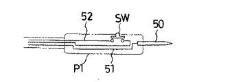
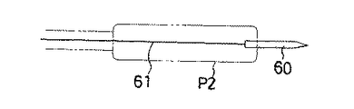
このように、従来の漏電遮断器用テスタでは、漏電遮断器の測定点にテスタの測定コードの先端の測定端子を接触させていても、動作テストを開始する際には、測定ボタンを操作するために測定端子のグリップから手を離してしまうため、何らかの方法で、漏電遮断器の測定点に測定端子を固定した後、動作テストを実施する必要があった。そこで、測定端子のグリップから手を離さずに、動作テストを開始することのできるリモコンスイッチ付きの測定端子が使用されている。この測定端子は測定ボタンとして機能するリモコンスイッチSWを測定端子に組込んだもので、図5に示されるように、リモコンスイッチ付きの測定端子50のプローブP1内には測定コード51とともにプローブP1内で折り返すリモコンケーブル52、リモコンスイッチSWなどの部品が内蔵されるため、プローブP1の内部構造が複雑になる。しかも、図6に示される通常の測定端子60のようにプローブP2内には測定コード61のみが内蔵された1芯の測定端子60に比べて、測定端子50では3芯のコードを使用する必要があり、製造工数が増加してコスト高となっており、漏電遮断器用テスタの改善が望まれていた。
【0004】
本発明は、漏電遮断器の測定点にテスタの(1芯の測定コードの)測定端子を接触させるだけで、測定開始ボタンを操作することなく漏電遮断器の動作テストを行える漏電遮断器テスタを提供することを目的とする。
【0005】
【課題を解決するための手段】
請求項1に記載の発明は、入力端子が電源側電圧線に接続され出力端子が負荷側電圧線に接続されて動作テストが行われ、漏電の発生を検出したときに負荷側電圧線との接続を解除する漏電遮断器における前記動作テストに使用される漏電遮断器用テスタであって、一対の測定端子と、該一対の測定端子が前記漏電遮断器の入力端子と出力端子に接続されると前記電源側電圧線間の電圧が入力される電圧検出回路と、該電圧検出回路が読み出した電圧値を表示する表示部と、前記一対の測定端子間に定電流出力を供給する定電流出力回路と、前記電圧検出回路の検出した電圧を読み出して所定時間が経過すると前記読み出しを停止して前記定電流出力回路から前記測定端子間に定電流出力を供給して漏電遮断器の動作テストを開始するマイコンと、を備えたことを特徴とする。
【0006】
【発明の実施の形態】
次に、本発明に係る漏電遮断器用テスタの実施の形態を添付図面に基づいて説明する。図1は本発明に係る漏電遮断器用テスタで漏電遮断器の動作テストを行う形態を示す概略図、図2は図1の漏電遮断器の動作テストにおける漏電遮断器用テスタのブロック図、図3は図1の漏電遮断器の動作テストにおける漏電遮断器用テスタのフロチャート、図4は図1の漏電遮断器用テスタの一対の測定端子間の電圧のタイミングチャートである。
【0007】
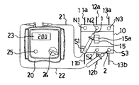
図1において、漏電遮断器10は、例えば、単相3線式又は3相3線式の3本の電源側電圧線11a,12a,13a(電源側電圧線の1本12aは中性線)に3つの入力端子N1,N2,N3がそれぞれ接続されて使用され、常時は、漏電遮断器10の3つの入力端子N1,N2,N3は、それぞれ対応する各出力端子S1,S2,S3及び各出力端子S1,S2,S3と接続された負荷側電圧線11b,12b,13bにそれぞれ接続され、2本の負荷側電圧線11b,12b間(又は、11b,13b間、又は、12b,13b間)から取り出された電圧が図示しない負荷に供給されている。
【0008】
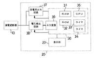
また、漏電遮断器用テスタ20には、メモリであるRAM31、ROM32を、タイマ33、タイマ34、CPU35、AD変換回路36等を備えたマイコン30、及び、定電流出力回路37、電圧検出回路38等が内臓され、また、液晶などの表示部23が設けられている。そして、漏電遮断器用テスタ20には、先端に測定端子1が設けられた測定コード21、及び、先端に測定端子2が設けられた測定コード22が接続されている。
【0009】
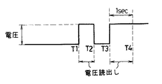
漏電遮断器10の動作テストを行う作業者は、負荷側電圧線11b,12b,13bに負荷が接続されていないことを確認して、漏電遮断器用テスタ20のロータリースイッチ24を回動操作する。これにより漏電遮断器用テスタ20は電源が投入されて稼動してマイコン30がスタンバイモードになり、ステップ1でタイマ33が初期化される。そして作業者が(測定ボタン25をリモート位置に設定した後)、漏電遮断器用テスタ20から測定コード21,22を引出して、測定端子1を漏電遮断器10の一方の測定点である入力端子N2に接続し、測定端子2を漏電遮断器10の他方の測定点である出力端子S3に接続すると、漏電遮断器用テスタ20の2本の測定コード21,22間の電圧が電圧検出回路38に入力され、電圧検出回路38は図4のタイミングチャートに示される電圧を検出し、マイコン30はこの検出した電圧を読み出す。
【0010】
例えばマイコン30が時間T1で電圧を読み出し始めるとステップ2に移行してタイマ33が駆動され、測定コード21,22間で電圧が読み出された時点からの時間がカウントされる。そして、時間T2において作業者が測定端子1,2と漏電遮断器10の各測定点(入力端子N2、出力端子S3)との接触を離してしまった場合には、ステップ1に戻り時間T3で再び、電圧が読み出された時点からの時間がカウントされる。この間、漏電遮断器用テスタ20では、読み出された電圧値が表示部23に表示される。
【0011】
そして、マイコン30で電圧が読み出された時点から所定時間(約1秒間)経過すると、ステップ3に移行してマイコン30は電圧の読み出しを停止し、定電流出力回路から測定端子2に試験電流(定電流出力)の供給が開始され、測定コード21,22間に漏電テストを行うための試験電流が流れる。同時にタイマ34が駆動され、測定コード21,22間に試験電流の供給を開始された時点からの時間が表示部23に表示され、漏電遮断器用テスタ20は、漏電遮断器の動作テストを開始する。このように所定時間が経過してから動作テストが開始されるように構成したのは、作業者の手の震えなどによる漏電遮断器の測定点とテスタの測定コードとの接触不良に起因するチャタリングによる誤測定を防止するためである。
【0012】
こうして試験電流が漏電遮断器用テスタ20の2本の測定コード21,22間に流れて測定が開始されると、試験電流は、電源側電圧線13a、入力端子N3、漏電遮断器10の内部回路、出力端子S3、測定コード22、漏電遮断器用テスタ20の内部の定電流回路、測定コード21、入力端子N2、電源側電圧線12aを通って流れる。この場合、入力端子N3と出力端子S3間、又は、入力端子N2と出力端子S2間のいずれかで、漏電遮断器10の内部回路に電流が流れることで、図示しない漏電検出回路Pが動作して(例えば、入力端子N3と出力端子S3間、及び、入力端子N2と出力端子S2間の双方に電流が流れたか否かを監視する。)漏電の検出が可能になる。
【0013】
図1の構成での漏電テストの場合は、出力端子S2と入力端子N2間に電流が流れないので、漏電検出回路Pは漏れ電流があったと判断してブレーカスイッチ15をオン動作させ、ブレーカスイッチ15の操作ノブ15aが移動し図示の中央の位置から下方の位置に切り替わり(ブレーカが落ちる)、3本の電源側電圧線11a,12a,13aのそれぞれに対応する負荷側電圧線11b,12b,13bとの接続を解除する。漏電遮断器用テスタ20の表示部23では、2本の測定コード21,22間に試験電流が流れて測定が開始されてからブレーカスイッチ15の操作ノブ15aが切り替わる(ブレーカが落ちる)までの時間、漏電遮断器10への試験電流値が表示され、作業者による漏電遮断器10の動作確認がなされる。
【0014】
漏電遮断器用テスタ20では、試験電流を少ない別の値に変えて漏電遮断器10の不動作確認を行ったり、ブレーカスイッチ15の操作ノブ15aを元に戻すとともに、試験電流を別の大きい値に変えて再度、漏電遮断器10の動作確認が同様に行われる。
【0015】
このように漏電遮断器用テスタでは、漏電遮断器の測定点にテスタの測定端子を接触させるだけで、測定開始ボタンを操作することなく漏電遮断器の動作テストを行える。そして、測定時に測定端子のグリップから手を離し測定ボタンを押す必要が無いため、測定端子を漏電遮断器に取り付けて外れないように固定する必要が無く、また、測定後に取り付けた測定端子を取り外す作業も必要でないため、簡単に測定が行え、次の測定場所への移動もスムーズに行える。
【0016】
また、従来機種においては、測定端子と漏電遮断器との接続が正常であるかという確認を、操作者が行った上で、測定ボタンを押していたが、本発明では、漏電遮断器の端子間の電圧を測定した上で自動的に漏電遮断器の動作テストを行うことで、漏電遮断器との接続が正常であるという判断を漏電遮断器テスタが行い、そのため正確で且つ簡単に測定を実施することができる。
【0017】
【発明の効果】
以上説明したように、本発明の漏電遮断器用テスタによれば、漏電遮断器の測定点にテスタの(1芯の)測定コードの先端の測定端子を接触させて漏電遮断器用テスタを稼動させて、所定時間が経過すれば、特に測定ボタンを操作しなくとも、自動的に動作テストが開始される。したがって、漏電遮断器の測定点にテスタの測定端子を接触させるだけで、測定開始ボタンを操作することなく漏電遮断器の動作テストを行えるので、漏電遮断器の動作テストを行う作業者の負担は軽減される。また、漏電遮断器用テスタを稼動させて所定時間が経過してから動作テストが開始されるようにしたので、作業者の手の震えなどによる漏電遮断器の測定点とテスタの測定端子との接触不良に起因するチャタリングによる誤測定も防止される等優れた効果を奏する。
【図面の簡単な説明】
【図1】本発明に係る漏電遮断器用テスタで漏電遮断器の動作テストを行う形態を示す概略図である。
【図2】図1の漏電遮断器の動作テストにおける漏電遮断器用テスタのブロック図である。
【図3】図1の漏電遮断器の動作テストにおける漏電遮断器用テスタのフロチャートである。
【図4】図1の漏電遮断器用テスタの一対の測定端子間の電圧のタイミングチャートである。
【図5】リモコンスイッチ付きの測定端子の概略図である。
【図6】通常の測定端子の概略図である。
【符号の説明】
1,2 測定端子
10 漏電遮断器
11a,12a,13a 電源側電圧線
11b,12b,13b 負荷側電圧線
15 ブレーカスイッチ
15a 操作ノブ
20 漏電遮断器用テスタ
21,22 測定コード
23 表示部
30 マイコン
31 RAM
32 ROM
33,34 タイマ
35 CPU
36 AD変換回路
37 定電流出力回路
38 電圧検出回路
50,60 測定端子
51,61 測定コード
52 リモコンケーブル
N1,N2,N3 入力端子
P1,P2 プローブ
S1,S2,S3 出力端子
SW リモコンスイッチ[0001]
BACKGROUND OF THE INVENTION
The present invention relates to an earth leakage breaker tester used for confirming that an operation in which an earth leakage breaker normally cuts off a main circuit is performed in the operation test of the earth leakage breaker.
[0002]
[Prior art]
When performing an earth leakage breaker operation test using a conventional earth leakage breaker tester, the operator uses the earth leakage breaker tester to fix the measurement terminal at the tip of the tester measurement cord to the measurement point of the earth leakage breaker. The operation test is started by releasing the grip of the measurement terminal and operating the measurement button of the earth leakage circuit breaker tester.
[0003]
[Problems to be solved by the invention]
Thus, in the conventional earth leakage circuit breaker tester, even when the measurement terminal at the tip of the tester measurement cord is in contact with the measurement point of the earth leakage breaker, the measurement button is operated when starting the operation test. Therefore, it was necessary to perform an operation test after fixing the measurement terminal to the measurement point of the earth leakage breaker by some method. Therefore, a measurement terminal with a remote control switch that can start an operation test without removing the hand from the grip of the measurement terminal is used. This measurement terminal incorporates a remote control switch SW functioning as a measurement button in the measurement terminal. As shown in FIG. 5, the probe P1 of the
[0004]
The present invention provides an earth leakage circuit breaker tester that can perform an operation test of the earth leakage breaker without operating the measurement start button by simply bringing the measurement terminal (of a single core measurement cord) into contact with the measurement point of the earth leakage breaker. The purpose is to provide.
[0005]
[Means for Solving the Problems]
According to the first aspect of the present invention, when the operation test is performed with the input terminal connected to the power supply side voltage line and the output terminal connected to the load side voltage line, and the occurrence of leakage is detected , An earth leakage circuit breaker tester used for the operation test in the earth leakage breaker for releasing connection , wherein a pair of measurement terminals , and the pair of measurement terminals are connected to an input terminal and an output terminal of the earth leakage breaker A voltage detection circuit for inputting a voltage between the power supply side voltage lines, a display unit for displaying a voltage value read by the voltage detection circuit, and a constant current output circuit for supplying a constant current output between the pair of measurement terminals When the voltage detected by the voltage detection circuit is read and a predetermined time elapses, the reading is stopped and a constant current output is supplied from the constant current output circuit to the measurement terminals to perform an operation test of the leakage breaker. Myco to start Characterized by comprising a and.
[0006]
DETAILED DESCRIPTION OF THE INVENTION
Next, an embodiment of an earth leakage circuit breaker tester according to the present invention will be described with reference to the accompanying drawings. FIG. 1 is a schematic diagram showing an embodiment of an earth leakage circuit breaker operation test using the earth leakage breaker tester according to the present invention, FIG. 2 is a block diagram of the earth leakage breaker tester in the operation test of the earth leakage breaker of FIG. FIG. 4 is a flowchart of the voltage between a pair of measurement terminals of the earth leakage breaker tester in FIG. 1. FIG. 4 is a flowchart of the earth leakage breaker tester in the operation test of the earth leakage breaker in FIG.
[0007]
In FIG. 1, the
[0008]
The earth leakage
[0009]
An operator who performs an operation test of the
[0010]
For example, when the
[0011]
When a predetermined time (about 1 second) elapses from the time when the voltage is read by the
[0012]
Thus, when the test current flows between the two
[0013]
In the case of the leakage test in the configuration of FIG. 1, since no current flows between the output terminal S2 and the input terminal N2, the leakage detection circuit P determines that there is a leakage current, and turns on the
[0014]
In the earth leakage
[0015]
As described above, the earth leakage breaker tester can perform the operation test of the earth leakage breaker without operating the measurement start button only by bringing the measurement terminal of the tester into contact with the measurement point of the earth leakage breaker. And since there is no need to release the grip of the measurement terminal and press the measurement button during measurement, there is no need to fix the measurement terminal to the earth leakage breaker so that it does not come off, and remove the measurement terminal attached after measurement Since no work is required, measurement can be performed easily, and movement to the next measurement location can be performed smoothly.
[0016]
In addition, in the conventional model, the operator checked whether the connection between the measurement terminal and the earth leakage breaker was normal, and then pressed the measurement button.In the present invention, between the terminals of the earth leakage breaker, The earth leakage circuit breaker tester makes a judgment that the connection with the earth leakage breaker is normal by automatically performing an operation test of the earth leakage breaker after measuring the voltage of the earth leakage, so that the measurement is performed accurately and easily. can do.
[0017]
【The invention's effect】
As described above, according to the earth leakage breaker tester of the present invention, the earth leakage breaker tester is operated by bringing the measurement terminal at the tip of the test cord (one core) of the tester into contact with the measurement point of the earth leakage breaker. When the predetermined time has elapsed, the operation test is automatically started without operating the measurement button. Therefore, just by bringing the tester's measurement terminal into contact with the measurement point of the earth leakage breaker, the operation test of the earth leakage breaker can be performed without operating the measurement start button. It is reduced. In addition, since the operation test is started after a predetermined time has elapsed since the earth leakage circuit breaker tester was activated, contact between the earth leakage breaker measurement point and the tester measurement terminal due to shaking of the operator's hand, etc. There are excellent effects such as preventing erroneous measurement due to chattering caused by defects.
[Brief description of the drawings]
FIG. 1 is a schematic view showing an embodiment in which an operation test of an earth leakage circuit breaker is performed by the earth leakage circuit breaker tester according to the present invention.
2 is a block diagram of a circuit breaker tester in the operation test of the circuit breaker of FIG. 1. FIG.
FIG. 3 is a flowchart of a circuit breaker tester in the operation test of the circuit breaker of FIG.
4 is a timing chart of a voltage between a pair of measurement terminals of the earth leakage circuit breaker tester of FIG. 1; FIG.
FIG. 5 is a schematic view of a measurement terminal with a remote control switch.
FIG. 6 is a schematic view of a normal measurement terminal.
[Explanation of symbols]
1, 2
32 ROM
33, 34
36
Claims (1)
一対の測定端子と、該一対の測定端子が前記漏電遮断器の入力端子と出力端子に接続されると前記電源側電圧線間の電圧が入力される電圧検出回路と、該電圧検出回路が読み出した電圧値を表示する表示部と、前記一対の測定端子間に定電流出力を供給する定電流出力回路と、前記電圧検出回路の検出した電圧を読み出して所定時間が経過すると前記読み出しを停止して前記定電流出力回路から前記測定端子間に定電流出力を供給して漏電遮断器の動作テストを開始するマイコンと、を備えたことを特徴とする漏電遮断器用テスタ。In the leakage breaker in which the input terminal is connected to the power supply side voltage line and the output terminal is connected to the load side voltage line, the operation test is performed, and the connection with the load side voltage line is released when the occurrence of leakage is detected. An earth leakage circuit breaker tester used for an operation test ,
A pair of measurement terminals , a voltage detection circuit for inputting a voltage between the power supply side voltage lines when the pair of measurement terminals are connected to an input terminal and an output terminal of the earth leakage circuit breaker , and the voltage detection circuit reads A display unit for displaying the measured voltage value, a constant current output circuit for supplying a constant current output between the pair of measurement terminals, and reading out the voltage detected by the voltage detection circuit and stopping the reading when a predetermined time elapses. And a microcomputer for starting an operation test of the earth leakage breaker by supplying a constant current output from the constant current output circuit to the measurement terminals .
Priority Applications (1)
| Application Number | Priority Date | Filing Date | Title |
|---|---|---|---|
| JP2001396116A JP4004792B2 (en) | 2001-12-27 | 2001-12-27 | Tester for earth leakage circuit breaker |
Applications Claiming Priority (1)
| Application Number | Priority Date | Filing Date | Title |
|---|---|---|---|
| JP2001396116A JP4004792B2 (en) | 2001-12-27 | 2001-12-27 | Tester for earth leakage circuit breaker |
Publications (3)
| Publication Number | Publication Date |
|---|---|
| JP2003197083A JP2003197083A (en) | 2003-07-11 |
| JP2003197083A5 JP2003197083A5 (en) | 2004-10-28 |
| JP4004792B2 true JP4004792B2 (en) | 2007-11-07 |
Family
ID=27602305
Family Applications (1)
| Application Number | Title | Priority Date | Filing Date |
|---|---|---|---|
| JP2001396116A Expired - Lifetime JP4004792B2 (en) | 2001-12-27 | 2001-12-27 | Tester for earth leakage circuit breaker |
Country Status (1)
| Country | Link |
|---|---|
| JP (1) | JP4004792B2 (en) |
Families Citing this family (4)
| Publication number | Priority date | Publication date | Assignee | Title |
|---|---|---|---|---|
| JP5452294B2 (en) * | 2010-03-10 | 2014-03-26 | 中国電力株式会社 | Fuse clip |
| JP2017168330A (en) * | 2016-03-17 | 2017-09-21 | テンパール工業株式会社 | Portable earth leakage tester |
| JP2017169375A (en) * | 2016-03-17 | 2017-09-21 | テンパール工業株式会社 | Portable earth leakage tester |
| JP2017181119A (en) * | 2016-03-29 | 2017-10-05 | テンパール工業株式会社 | Portable earth leakage operation tester |
-
2001
- 2001-12-27 JP JP2001396116A patent/JP4004792B2/en not_active Expired - Lifetime
Also Published As
| Publication number | Publication date |
|---|---|
| JP2003197083A (en) | 2003-07-11 |
Similar Documents
| Publication | Publication Date | Title |
|---|---|---|
| JP4004792B2 (en) | Tester for earth leakage circuit breaker | |
| CN108535549A (en) | A kind of hand-held three-phase transformer instrument for measuring DC resistance | |
| JP2004226179A (en) | Pressure tester | |
| CN111257674A (en) | Test system of converter | |
| JP4268314B2 (en) | Cable failure display device | |
| CN113985132A (en) | Insulation resistance measuring device and method for standby motor | |
| JP3166968U (en) | Circuit meter alarm and circuit meter with alarm | |
| JP2000214194A (en) | Insulation resistance tester | |
| JP3856187B2 (en) | Operation tester for earth leakage breaker | |
| CN209802686U (en) | A dehumidifier test device with self-judgment production mode | |
| JP4764694B2 (en) | Withstand voltage test equipment | |
| JP2005020863A (en) | Position check device for drawer type circuit breaker unit in switchboard | |
| JP4485620B2 (en) | Switchboard automatic test equipment | |
| JP3036705B2 (en) | Electrolytic capacitor reverse connection detection device | |
| CN222800857U (en) | Coil instantaneous working condition detection device of relay contactor | |
| CN222734192U (en) | GIS conductive loop resistance testing device | |
| CN222748671U (en) | Drawer switch diagnostic device | |
| JP2540127B2 (en) | Programmable controller failure diagnosis device | |
| CN201548624U (en) | Test equipment for control screen of generator set | |
| CN115902385B (en) | A single-phase energy meter, a three-phase metering device and a metering method | |
| JPH04102075A (en) | Power on/off testing device | |
| JP3227477B2 (en) | Protection relay and tester and test system | |
| CN213750086U (en) | Electricity testing and phase checking device of high-voltage cabinet | |
| CN214703684U (en) | Automatic countdown device for withstand voltage test of power equipment | |
| KR102805763B1 (en) | Universal checking device of auxiliary relay |
Legal Events
| Date | Code | Title | Description |
|---|---|---|---|
| A977 | Report on retrieval |
Free format text: JAPANESE INTERMEDIATE CODE: A971007 Effective date: 20061117 |
|
| A131 | Notification of reasons for refusal |
Free format text: JAPANESE INTERMEDIATE CODE: A131 Effective date: 20061205 |
|
| A521 | Request for written amendment filed |
Free format text: JAPANESE INTERMEDIATE CODE: A523 Effective date: 20070201 |
|
| TRDD | Decision of grant or rejection written | ||
| A01 | Written decision to grant a patent or to grant a registration (utility model) |
Free format text: JAPANESE INTERMEDIATE CODE: A01 Effective date: 20070724 |
|
| A61 | First payment of annual fees (during grant procedure) |
Free format text: JAPANESE INTERMEDIATE CODE: A61 Effective date: 20070822 |
|
| R150 | Certificate of patent or registration of utility model |
Ref document number: 4004792 Country of ref document: JP Free format text: JAPANESE INTERMEDIATE CODE: R150 Free format text: JAPANESE INTERMEDIATE CODE: R150 |
|
| FPAY | Renewal fee payment (event date is renewal date of database) |
Free format text: PAYMENT UNTIL: 20100831 Year of fee payment: 3 |
|
| FPAY | Renewal fee payment (event date is renewal date of database) |
Free format text: PAYMENT UNTIL: 20110831 Year of fee payment: 4 |
|
| R250 | Receipt of annual fees |
Free format text: JAPANESE INTERMEDIATE CODE: R250 |
|
| FPAY | Renewal fee payment (event date is renewal date of database) |
Free format text: PAYMENT UNTIL: 20110831 Year of fee payment: 4 |
|
| FPAY | Renewal fee payment (event date is renewal date of database) |
Free format text: PAYMENT UNTIL: 20120831 Year of fee payment: 5 |
|
| R250 | Receipt of annual fees |
Free format text: JAPANESE INTERMEDIATE CODE: R250 |
|
| FPAY | Renewal fee payment (event date is renewal date of database) |
Free format text: PAYMENT UNTIL: 20120831 Year of fee payment: 5 |
|
| FPAY | Renewal fee payment (event date is renewal date of database) |
Free format text: PAYMENT UNTIL: 20130831 Year of fee payment: 6 |
|
| R250 | Receipt of annual fees |
Free format text: JAPANESE INTERMEDIATE CODE: R250 |
|
| R250 | Receipt of annual fees |
Free format text: JAPANESE INTERMEDIATE CODE: R250 |
|
| R250 | Receipt of annual fees |
Free format text: JAPANESE INTERMEDIATE CODE: R250 |
|
| R250 | Receipt of annual fees |
Free format text: JAPANESE INTERMEDIATE CODE: R250 |
|
| R250 | Receipt of annual fees |
Free format text: JAPANESE INTERMEDIATE CODE: R250 |
|
| R250 | Receipt of annual fees |
Free format text: JAPANESE INTERMEDIATE CODE: R250 |
|
| R250 | Receipt of annual fees |
Free format text: JAPANESE INTERMEDIATE CODE: R250 |
|
| S533 | Written request for registration of change of name |
Free format text: JAPANESE INTERMEDIATE CODE: R313533 |
|
| R350 | Written notification of registration of transfer |
Free format text: JAPANESE INTERMEDIATE CODE: R350 |
|
| R250 | Receipt of annual fees |
Free format text: JAPANESE INTERMEDIATE CODE: R250 |
|
| R250 | Receipt of annual fees |
Free format text: JAPANESE INTERMEDIATE CODE: R250 |
|
| R250 | Receipt of annual fees |
Free format text: JAPANESE INTERMEDIATE CODE: R250 |
|
| EXPY | Cancellation because of completion of term |