JP4005964B2 - ピストンリングの検査方法及びその装置 - Google Patents
ピストンリングの検査方法及びその装置 Download PDFInfo
- Publication number
- JP4005964B2 JP4005964B2 JP2003368681A JP2003368681A JP4005964B2 JP 4005964 B2 JP4005964 B2 JP 4005964B2 JP 2003368681 A JP2003368681 A JP 2003368681A JP 2003368681 A JP2003368681 A JP 2003368681A JP 4005964 B2 JP4005964 B2 JP 4005964B2
- Authority
- JP
- Japan
- Prior art keywords
- piston
- ring
- piston ring
- peripheral surface
- outer peripheral
- Prior art date
- Legal status (The legal status is an assumption and is not a legal conclusion. Google has not performed a legal analysis and makes no representation as to the accuracy of the status listed.)
- Expired - Fee Related
Links
- 238000007689 inspection Methods 0.000 title claims description 41
- 238000000034 method Methods 0.000 title claims description 17
- 230000002093 peripheral effect Effects 0.000 claims description 26
- 238000012545 processing Methods 0.000 claims description 12
- 238000012790 confirmation Methods 0.000 description 2
- 230000000694 effects Effects 0.000 description 2
- 238000001125 extrusion Methods 0.000 description 2
- 238000012546 transfer Methods 0.000 description 2
- 230000002159 abnormal effect Effects 0.000 description 1
- 230000002411 adverse Effects 0.000 description 1
- 238000003384 imaging method Methods 0.000 description 1
- 230000001771 impaired effect Effects 0.000 description 1
- 230000001678 irradiating effect Effects 0.000 description 1
- 239000010687 lubricating oil Substances 0.000 description 1
- 238000007790 scraping Methods 0.000 description 1
- 238000012360 testing method Methods 0.000 description 1
- 238000011179 visual inspection Methods 0.000 description 1
Images


Landscapes
- Investigating Materials By The Use Of Optical Means Adapted For Particular Applications (AREA)
- Pistons, Piston Rings, And Cylinders (AREA)
Description
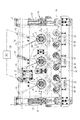
図1は本発明に係るピストンリングの検査方法に用いられる検査装置全体の概略平面図、図2はその要部の側面図、図3は同検査装置の要部の縦断正面図である。これら図1〜3において、1は床面に立設された架台2に図外のエアシリンダーを介して昇降自在に支持された装置フレームであり、この装置フレーム1にはベアリング3a付き筒状軸受部材3を介して縦軸4が回転自在に支承されている。
前記ピストン5を縦向き姿勢に収容保持しているパレットが水平搬送コンベアにより検査装置内部のピストン移動経路に搬入されて所定位置に停止されると、装置フレーム1が下降されて縦軸4下端部のハンドユニット6がピストン5を挟持し、続く装置フレーム1の上昇によって該ピストン5が図7に示すような所定高さ位置まで上昇される。
14(14a〜14d) リング溝
15 レーザー(光源)
16 CCDカメラ
19 ピストンリング押出用ローラ
20 PC(撮影画像のデータ処理及び表示手段)
21(21a〜21d) ピストンリング
21A 飛び出し外周面部分
21B ピストンリング合口部
LB レーザー光
Claims (6)
- ピストン外周にその軸線方向に所定間隔を隔てて形成した複数のリング溝に組付けられたピストンリングの検査方法であって、
ピストンの側方位置から前記ピストンリング組付け位置に向けてピストン径方向に対して傾斜する方向の光を照射し、この光照射状態でピストンをその軸心周りに回転させてその外周面一周分の画像を前記のピストン側方位置からカメラで撮影することにより、各ピストンリングの有無及び各ピストンリング合口部の周方向位置を確認するとともに、前記撮影画像のデータ処理により、各ピストンリング合口部の幅の合否を判定することを特徴とするピストンリングの検査方法。 - 前記ピストンの回転時に、光照射及びカメラ撮影位置とは反対側からピストン外周面にローラを押圧させることによって、各ピストンリングの光照射及びカメラ撮影側の外周面部分をピストン外周面の外方へ飛び出させて一周分の画像を撮影する請求項1に記載のピストンリングの検査方法。
- 前記照射光として、レーザー光を使用する請求項1または2に記載のピストンリングの検査方法。
- ピストン外周にその軸線方向に所定間隔を隔てて形成した複数のリング溝に組付けられたピストンリングの検査装置であって、
ピストンの側方位置に配置され前記ピストンリング組付け位置に向けてピストン径方向に対して傾斜する方向の光を照射する光源と、ピストンをその軸心周りに回転させるピストン回転機構と、前記ピストンの側方位置に配置されピストンの回転時にその外周面一周分の画像を撮影するカメラと、その撮影画像のデータ処理により各ピストンリング合口部の幅の合否判定画面を表示する手段とを備えていることを特徴とするピストンリングの検査装置。 - 前記の光線照射及びカメラ撮影位置とは反対側のピストンの側方位置には、ピストンの回転時にピストン外周面に押圧されて各ピストンリングの光照射及びカメラ撮影側の外周面部分をピストン外周面の外方へ飛び出させるリング押出用ローラが設けられている請求項4に記載のピストンリングの検査装置。
- 前記光源が、レーザーである請求項4または5に記載のピストンリングの検査装置。
Priority Applications (1)
| Application Number | Priority Date | Filing Date | Title |
|---|---|---|---|
| JP2003368681A JP4005964B2 (ja) | 2003-10-29 | 2003-10-29 | ピストンリングの検査方法及びその装置 |
Applications Claiming Priority (1)
| Application Number | Priority Date | Filing Date | Title |
|---|---|---|---|
| JP2003368681A JP4005964B2 (ja) | 2003-10-29 | 2003-10-29 | ピストンリングの検査方法及びその装置 |
Publications (2)
| Publication Number | Publication Date |
|---|---|
| JP2005133598A JP2005133598A (ja) | 2005-05-26 |
| JP4005964B2 true JP4005964B2 (ja) | 2007-11-14 |
Family
ID=34646275
Family Applications (1)
| Application Number | Title | Priority Date | Filing Date |
|---|---|---|---|
| JP2003368681A Expired - Fee Related JP4005964B2 (ja) | 2003-10-29 | 2003-10-29 | ピストンリングの検査方法及びその装置 |
Country Status (1)
| Country | Link |
|---|---|
| JP (1) | JP4005964B2 (ja) |
Families Citing this family (3)
| Publication number | Priority date | Publication date | Assignee | Title |
|---|---|---|---|---|
| JP5331529B2 (ja) * | 2009-03-23 | 2013-10-30 | 日産自動車株式会社 | ピストンリングの合口位置のずれ検出方法、及びずれ検出装置 |
| JP6114051B2 (ja) * | 2013-02-07 | 2017-04-12 | 本田技研工業株式会社 | ワーク組立装置及びワーク組立方法 |
| JP6237266B2 (ja) * | 2014-01-27 | 2017-11-29 | トヨタ自動車株式会社 | ピストンサイドレールの欠品検査装置 |
-
2003
- 2003-10-29 JP JP2003368681A patent/JP4005964B2/ja not_active Expired - Fee Related
Also Published As
| Publication number | Publication date |
|---|---|
| JP2005133598A (ja) | 2005-05-26 |
Similar Documents
| Publication | Publication Date | Title |
|---|---|---|
| JP6740089B2 (ja) | ロボット装置、検査装置、発電機の検査装置、および検査方法 | |
| JP5014170B2 (ja) | ワーク外観検査装置 | |
| JP7374360B2 (ja) | 軸受要素検査システムおよび方法 | |
| JP6817893B2 (ja) | 外観検査装置 | |
| JP6936995B2 (ja) | 立体物の外観検査装置 | |
| JP6520216B2 (ja) | ワーク検査装置及び転がり軸受の製造方法 | |
| JP2013522599A (ja) | ボア検査システムおよび、これを用いた検査方法 | |
| TW201915441A (zh) | 檢查裝置及檢查方法 | |
| JP4005964B2 (ja) | ピストンリングの検査方法及びその装置 | |
| JP5794895B2 (ja) | 円筒形状物の外観検査装置 | |
| JP2003156453A (ja) | 側面検査方法 | |
| JP5128344B2 (ja) | オイルシールの検査装置 | |
| JP2010107220A (ja) | 非円筒体の外周面検査方法及びその装置 | |
| JP7194055B2 (ja) | 接合部の検査方法及び接合部の検査装置 | |
| JP4539387B2 (ja) | ベルト端面の検査装置および検査方法 | |
| JP6672897B2 (ja) | 検査装置及び回転体の検査方法 | |
| JP4065263B2 (ja) | ピストンリング回り止め用のノックピン圧入装置とノックピン圧入方法 | |
| JP4821987B2 (ja) | X線ct装置 | |
| JP6349227B2 (ja) | 気体の漏洩撮影装置 | |
| JP7501093B2 (ja) | 探傷装置、および探傷方法 | |
| JP6331080B2 (ja) | 軌道面姿勢計測方法、軌道面姿勢計測装置および転動体挙動計測方法 | |
| JP4608611B2 (ja) | 容器検査装置 | |
| JP2019124588A (ja) | 外観検査装置 | |
| JP6616812B2 (ja) | テーブルティルティング確認装置および確認方法 | |
| KR101230985B1 (ko) | 외관검사장치 |
Legal Events
| Date | Code | Title | Description |
|---|---|---|---|
| TRDD | Decision of grant or rejection written | ||
| A01 | Written decision to grant a patent or to grant a registration (utility model) |
Free format text: JAPANESE INTERMEDIATE CODE: A01 Effective date: 20070821 |
|
| A61 | First payment of annual fees (during grant procedure) |
Free format text: JAPANESE INTERMEDIATE CODE: A61 Effective date: 20070824 |
|
| R150 | Certificate of patent or registration of utility model |
Free format text: JAPANESE INTERMEDIATE CODE: R150 |
|
| FPAY | Renewal fee payment (event date is renewal date of database) |
Free format text: PAYMENT UNTIL: 20100831 Year of fee payment: 3 |
|
| FPAY | Renewal fee payment (event date is renewal date of database) |
Free format text: PAYMENT UNTIL: 20110831 Year of fee payment: 4 |
|
| FPAY | Renewal fee payment (event date is renewal date of database) |
Free format text: PAYMENT UNTIL: 20110831 Year of fee payment: 4 |
|
| FPAY | Renewal fee payment (event date is renewal date of database) |
Free format text: PAYMENT UNTIL: 20120831 Year of fee payment: 5 |
|
| LAPS | Cancellation because of no payment of annual fees |