JP4012425B2 - Laser lap welding method of aluminum galvanized steel sheet and aluminum galvanized steel sheet for laser lap welding - Google Patents
Laser lap welding method of aluminum galvanized steel sheet and aluminum galvanized steel sheet for laser lap welding Download PDFInfo
- Publication number
- JP4012425B2 JP4012425B2 JP2002099462A JP2002099462A JP4012425B2 JP 4012425 B2 JP4012425 B2 JP 4012425B2 JP 2002099462 A JP2002099462 A JP 2002099462A JP 2002099462 A JP2002099462 A JP 2002099462A JP 4012425 B2 JP4012425 B2 JP 4012425B2
- Authority
- JP
- Japan
- Prior art keywords
- steel sheet
- aluminum
- laser
- lap welding
- gap
- Prior art date
- Legal status (The legal status is an assumption and is not a legal conclusion. Google has not performed a legal analysis and makes no representation as to the accuracy of the status listed.)
- Expired - Fee Related
Links
Images
Landscapes
- Laser Beam Processing (AREA)
Description
【0001】
【発明の属する技術分野】
本発明は、アルミニウム系めっき鋼板のレーザー重ね溶接方法およびレーザー重ね溶接用アルミニウム系めっき鋼板に関する。
【0002】
【従来の技術】
アルミニウム系めっき鋼板は各種の建材、自動車部品、容器、幅広い分野で使用されているが、長期間の防錆効果を確保する目的からは厚目付けのめっきが有効である。例えば、腐食環境が厳しい自動車燃料タンク用のめっき鋼板としては、めっき付着量が30g/m2以上の厚目付けアルミニウム系めっき鋼板が使用されはじめている。アルミニウム系めっき鋼板としては、実質的にAlおよび不可避不純物からなる溶融アルミニウムめっき鋼板、Al中にSiを5〜10%程度含有する溶融アルミニウム合金めっき鋼板、あるいはさらにAl中にSi、Mg、Ca、Znなどを含有する溶融アルミニウム合金めっき鋼板、Al中にZnを40〜45%程度とSiを0.5〜3%程度含有する溶融アルミニウム合金めっき鋼板などがある。
【0003】
これらのアルミニウム系めっき鋼板は、総じて溶接性に優れており、各種の溶接法が適用されてきた。溶接性としては溶接方法と密接な関係があるが、めっき付着量の多いアルミニウム系めっき鋼板をレーザーで重ね溶接した場合には、アルミニウム系めっき鋼板でも溶接性が劣る場合がある。ここでレーザー重ね溶接とは、2枚あるいはそれ以上の鋼板を重ね、鋼板表面にほぼ垂直な方向からレーザービームを照射してキーホール溶接する方法をいう。アルミニウム系めっき鋼板では、2枚の鋼板の間に存在するめっき金属がレーザービームで加熱され、アルミニウムが溶融・気化して蒸発し、このアルミニウム蒸気の圧力によって溶融池の溶鋼が吹き飛ばされて溶接欠陥(ピット)を生じたり、アルミニウム蒸気が溶鋼中に閉じ込められて凝固することによるブローホール、あるいはアルミニウムが溶接金属内部で偏在することによるFe−Al金属間化合物の生成、といった欠陥が発生する場合がある。
【0004】
かかるレーザー重ね溶接における課題を解決する手段として、アルミニウム系めっき鋼板に対して提案された例はほとんど見当たらないが、Zn系めっき鋼板のレーザー重ね溶接の場合には、例えば以下の技術が提案されている。
特開平4−231190号公報には、前処理工程で予め亜鉛系めっきを加熱して除去した後にレーザー重ね溶接する方法が開示されている。しかし、この方法では、工程が2つ以上必要である上に、合わせ部の耐食性に課題が生ずる、という難点がある。
【0005】
特開平3−165994号公報には、予めめっき鋼板の重ね面にレーザーを吸収する材料を塗布しておく方法が開示されている。しかし、この方法においても工程が2つ以上必要であり、生産性およびコストの点で課題がある。
特許第3139325号の特許掲載公報には、Zn−Ni系合金めっき鋼板のめっき付着量と鋼板板厚との関係を限定することで、レーザー溶接における溶接欠陥が少なく、かつ溶接部外観の優れたZn−Ni系合金めっき鋼板が開示されている。しかし、この技術では例えば板厚が0.6mmではめっき付着量を15g/m2 以下としなければならず、亜鉛系めっき鋼板の最大の機能である耐食性が犠牲となり、厳しい腐食環境で長期間使用される自動車の耐久性が確保できない、という難点がある。
【0006】
【発明が解決しようとする課題】
本発明が解決しようとする課題は、生産性や防錆性能を犠牲にすることなく、溶接欠陥が少なく、かつ溶接部外観の優れたアルミニウム系めっき鋼板のレーザー重ね溶接方法およびレーザー重ね溶接に適したアルミニウム系めっき鋼板を提供することにある。
【0007】
【課題を解決するための手段】
本発明者らは、レーザー重ね溶接によるアルミニウム系めっき鋼板の溶接継ぎ手部について、溶接欠陥を低減し、優れた溶接部外観と継ぎ手強度を確保するための溶接方法およびそれに適した鋼板について、種々の検討と実験を続けた結果、ついに2枚の鋼板の間の間隔を制御し、この隙間と鋼板板厚と鋼板間に存在するアルミニウムの量との関係を特定の範囲に限定することで、溶接欠陥を低減し、優れた溶接部外観と継ぎ手強度を確保できる溶接方法を見出した。
【0008】
本発明はこうした知見に基づいてなされたもので、その要旨とするところは以下の通りである。
(1)アルミニウム系めっき鋼板のレーザー重ね溶接において、重ね溶接部の隙間:X(mm)、鋼板板厚:Y(mm)、重ね面の合計めっき付着量:Z(g/m2)とするとき、
X≧Z/(10000×Y)
X≦0.35×Y
を満足する部分を有し、
X≧Z/(10000×Y)
を満足しない部分の最大長さが3×Y(mm)以下であるよう重ね溶接部に隙間空間を設けることを特徴とするアルミニウム系めっき鋼板のレーザー重ね溶接方法。
【0009】
(2)アルミニウム系めっき鋼板のレーザー重ね溶接において、重ね溶接部の隙間:X(mm)、鋼板板厚:Y(mm)、重ね面の合計めっき付着量:Z(g/m2)とするとき、
X≧Z/(10000×Y)
X≦0.35×Y
を満足する部分を有し、
X≧Z/(10000×Y)
を満足しない部分の最大長さが3×Y(mm)以下であり、
X≧Z/(10000×Y)
X≦0.35×Y
を満足する部分の長さの合計L(mm)が、レーザー溶接線長:A(mm)に対して、
L≧A×0.3/Y
を満足するよう重ね溶接部に隙間空間を設けることを特徴とするアルミニウム系めっき鋼板のレーザー重ね溶接方法である。
【0010】
【発明の実施の形態】
以下、本発明を詳細に説明する。
発明者らは、種々のめっき鋼板、具体的には、めっき種としては溶融アルミニウムめっき鋼板、溶融アルミニウム合金めっき鋼板等のめっき鋼板で、めっき付着量としては片面あたり10〜100g/m2、板厚としては0.3〜2.3mmの鋼板を用い、種々の溶接条件でレーザー重ね溶接実験を行ない、溶接部外観を調べた。
【0011】
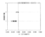
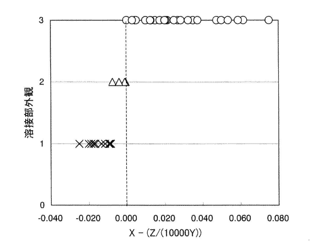
数多くの実験結果について整理した結果、健全な溶接部を得るための条件は、2枚の鋼板の隙間と鋼板板厚と重ね面のめっきの合計付着量の3者と非常に密接な関係があること、2枚の鋼板の隙間をX(mm)、鋼板板厚をY(mm)、重ね面のめっきの合計付着量をZ(g/m2 )とした時、図1に示すように
X≧Z/(10000×Y)
を満足すると、鋼板の隙間X、鋼板板厚Y、重ね面のめっきの合計付着量Zにかかわらず、溶接部外観が顕著に向上することを見出した。この結果に基づいて、本発明では2枚の鋼板の隙間をX(mm)、鋼板板厚をY(mm)、重ね面のめっきの合計付着量をZ(g/m2 )との関係を、X≧Z/(10000×Y)と規定した。
【0012】
ここで、2枚の鋼板の隙間Xは相対する鋼板のめっきの表面同士の間隔を意味し、めっきの表面に他の材料、例えば有機フィルムを介在させることによって、片側の鋼板のめっき表面ともう一方の鋼板のめっき表面との間に隙間を設けた場合にも、あくまでもめっき同士の表面の間隔を意味する。
鋼板板厚Yは、2枚の鋼板の板厚が同一である場合には片側の鋼板の板厚を意味し、2枚の鋼板の板厚が異なる場合には薄い方の鋼板の板厚を意味する。これは板厚の薄い鋼板の方がめっきが自由表面に到達しやすいからである。
【0013】
重ね面のめっきの合計付着量Zは2枚の鋼板の間に存在するめっきの量であって、片側の鋼板の内面側表面にあるめっきの量ともう一方の鋼板の内面側表面にあるめっきの量との合計量である。一方の鋼板がアルミニウム系めっき鋼板であり、もう一方の鋼板がめっきされていない鋼板である場合、一方あるいは両方の鋼板が片面だけアルミニウム系めっきされた鋼板である場合、一方あるいは両方の鋼板が差厚めっき鋼板(両面のめっき付着量が同一ではない鋼板)では、重ね溶接で内面側になる面のめっき付着量の合計が重要であり、これら鋼板の組み合わせである場合も本発明に含まれることは言うまでも無い。
【0014】
鋼板間の隙間Xが、X≦0.35×Yを満足すれば、溶接部外観の良好な溶接部が得られるが、X>0.35×Yでは、溶接条件をいかように制御しても健全な溶接部を得ることは困難である。さらに、2枚の鋼板間の隙間は、レーザー溶接の溶接線の全長にわたって確保されていてももちろん良いが、実用上は必ずしもその必要は無く、2枚の鋼板の隙間をX(mm)、鋼板板厚をY(mm)、重ね面のめっきの合計付着量をZ(g/m2 )とした時、
X≧Z/(10000×Y)
X≦0.35×Y
を満足する部分の長さの合計L(mm)がレーザー溶接線長A(mm)に対して、L≧A×0.3 /Yを満足すると、全長で隙間が確保されているのと実質的に同等の効果が得られる。
【0015】
LがA×0.3/Yよりも小さい場合にはビード形状が悪くなったり、スパッタ量が多くなる場合があり、Lが小さくなるほど溶接部の外観が劣化する。なお、重要なことはX≧Z/(10000×Y)を満足する部分の長さの合計Lを確保することであって、Xがさらに大きい部分があるからといって、隙間が必要以上に大きくなる効果は小さく、ましてや大きな隙間がある場合でも、LがA×0.3/Yよりも小さくできるということではない。2枚の鋼板間に隙間を設ける方法としては、前述の条件を満足する方法であれば適用可能であり、具体的には、下記の方法が有効である。
【0016】
2枚の鋼板の間に少なくとも溶接線上に固体有機物をスペーサーとして介在せしめ、溶接線に隙間を確保することは有効である。この場合、必ずしも全長にわたって配置することは絶対条件ではなく、
X≧Z/(10000×Y)
X≦0.35×Y
あるいは、X≧Z/(10000×Y)
X≦0.35×Y
を満足する部分の長さの合計L(mm)が、レーザー溶接線長:A(mm)に対して、
L≧A×0.3/Y
を満足するように配置すれば良い。
【0017】
この場合、固体有機物が少なくとも溶接線に存在していれば良く、そのままレーザー溶接することで顕著な溶接性向上防止効果が得られる。固体有機物の種類は特に限定されるものではなく、ポリアミド、ポリウレタン、ポリエステル、ポリエーテル、ポリオレフィン、ポリスチレン、などが代表的であり、これらの混合物であっても良い。2枚の鋼板の間に固体有機物を介在せしめる方法は特に限定されるものではなく、固体有機物のフィルムを貼付する方法、固体有機物を液体に分散して塗装する方法、など、対象物の形状や構造、コストに応じて選定することができる。
【0018】
鋼板表面の構造を空間変調することも、レーザー重ね溶接時の隙間を付与する有効な手段である。ここで、鋼板表面の構造を空間変調するとは、例えば鋼板表面のテクスチャーを微視的および/または巨視的に制御して所望のテクスチャーを得ることを意味する。この場合にも
X≧Z/(10000×Y)
X≦0.35×Y
あるいは、さらに
L≧A×0.3 /Y
を満足させることが必要であるのはもちろんである。
【0019】
鋼板表面の構造を空間変調するのは、鋼板段階であっても良いし、鋼板を部品形状に成形する途中の工程であっても良く、あるいは部品形状に成形した後でレーザー重ね溶接する前であっても良く、いずれにしろレーザー重ね溶接するまでに行えばいずれも効果が発揮される。鋼板の表面の全部または大部分を空間変調しても良く、あるいはレーザー重ね溶接する部分のみを空間変調してもいずれでも良く、部品形状や鋼板の外観、空間変調の方法に応じて選択すれば良い。
【0020】
鋼板表面の構造を空間変調する手段としては、例えば、鋼板に付与したい表面構造を有する金型やロールを鋼板表面に押し付けて転写する手段、高エネルギー密度ビームで鋼板表面の金属を局部的に蒸発・除去する手段、鋼板表面の金属を鋼板の幅および長手方向に分布を持たせ、かつ板厚方向にも分布を持たせて機械的に除去する手段、鋼板表面の金属をエッチングや電解などの化学的方法によって鋼板の幅および長手方向に分布を持たせ、かつ板厚方向にも分布を持たせて除去する手段、など、空間変調後のテクスチャーとコスト、生産性に応じて種々の手段を用いることができる。
【0021】
本発明が対象とするアルミニウム系めっき鋼板は、アルミニウムまたはアルミニウムを主体とする合金を鋼板表面(両面または片面)にめっきしたものであり、製法は工業的には溶融めっき、電気めっきが主流であるが、蒸着めっきなど他の製造方法であってももちろん構わない。また、めっき密着性や加工性などを向上する目的で、アルミニウムめっきに先行して他の金属をプレ処理すること、めっき後に有機、無機、あるいは有機+無機複合皮膜を付与すること、などは、用途に応じて適用することができ、これら前処理あるいは後処理を施したアルミニウム系めっき鋼板も本発明が対象とするものである。鋼板は通常自動車その他の製品に使われる鋼板であればすべて本発明の対象であり、特に鋼板の組成・組織・強度・延性等を限定するものではない。
【0022】
【実施例】
表1に示す鋼板を表1に示す条件でレーザー重ね溶接に供した。溶接はYAGレーザーで行い、出力は3kWであった。隙間の付与方法として、Aは両側の鋼板のそれぞれ片面に、幅0.1mm、深さ0.03mmで溶接線と80゜の角度を成して交わる溝を溶接線方向の間隔0.2mmで付与した鋼板とし、前記鋼板の溝が合わせ面に位置するようにして2枚の鋼板を重ねることで隙間を付与した。このとき、隙間の長さの合計は溶接線長の50%である。Bは、片側の鋼板を、幅0.15mm、深さ0.025mmで溶接線とほぼ直角を成して交わる溝を、溶接線方向の間隔1.0mmで付与した鋼板とし、もう一方の鋼板は通常の鋼板として、前記鋼板の溝が合わせ面に位置するようにして2枚の鋼板を重ねることで隙間を付与した。このとき、隙間の長さの合計は溶接線長の15%である。
【0023】
【表1】
溶接部外観は目視で評価し、結果は
○:外観が良好
△:一部ビード形状が悪い部分がある
×:大部分でビード形状が悪い
で表示した。
表1から、本発明例はいずれも溶接部外観が良好であることがわかる。これに対して本発明の要件を満足しない比較例では溶接部外観が不良である。
【0025】
【発明の効果】
以上述べた通り、本発明のレーザー重ね溶接方法およびアルミニウム系めっき鋼板は、健全で信頼性の高いレーザー重ね溶接部を提供するものであり、自動車、建築・住宅、等に広く適用することが可能で、産業の発展に大きく寄与するものである。
【図面の簡単な説明】
【図1】2枚の鋼板の間の隙間XおよびZ/(10000×Y)値(ここでZは合わせ面に存在するめっき量の合計付着量、Yは薄い方の鋼板の板厚)と溶接部外観の関係を示す図である。[0001]
BACKGROUND OF THE INVENTION
The present invention relates to a laser lap welding method for an aluminum-based plated steel sheet and an aluminum-based plated steel sheet for laser lap welding.
[0002]
[Prior art]
Aluminum-based plated steel sheets are used in various building materials, automobile parts, containers, and a wide range of fields, but thick plating is effective for the purpose of ensuring a long-term rust prevention effect. For example, as a plated steel sheet for an automobile fuel tank having a severe corrosive environment, a thick-weight aluminum-based plated steel sheet having a plating adhesion amount of 30 g / m 2 or more is beginning to be used. As the aluminum-based plated steel sheet, a molten aluminum-plated steel sheet substantially composed of Al and inevitable impurities, a molten aluminum alloy-plated steel sheet containing about 5 to 10% of Si in Al, or further Si, Mg, Ca, There are a molten aluminum alloy plated steel sheet containing Zn and the like, and a molten aluminum alloy plated steel sheet containing about 40 to 45% Zn and about 0.5 to 3% Si in Al.
[0003]
These aluminum-based plated steel sheets are generally excellent in weldability, and various welding methods have been applied. The weldability is closely related to the welding method, but when an aluminum-based plated steel sheet with a large amount of coating is lap welded with a laser, the weldability may be poor even with the aluminum-based plated steel sheet. Here, the laser lap welding refers to a method in which two or more steel plates are stacked and keyhole welding is performed by irradiating a laser beam from a direction substantially perpendicular to the steel plate surface. In the aluminum-based plated steel sheet, the plating metal existing between the two steel sheets is heated with a laser beam, the aluminum melts and vaporizes and evaporates, and the molten steel in the molten pool is blown away by the pressure of this aluminum vapor, resulting in welding defects. (Pits), defects such as blow holes due to aluminum vapor confined in the molten steel and solidification, or generation of Fe-Al intermetallic compounds due to uneven distribution of aluminum inside the weld metal may occur. is there.
[0004]
As a means for solving such problems in laser lap welding, there are hardly any examples proposed for aluminum-based plated steel sheets, but in the case of laser lap welding of Zn-based plated steel sheets, for example, the following techniques are proposed: Yes.
JP-A-4-231190 discloses a method of laser lap welding after the zinc-based plating is heated and removed in advance in the pretreatment step. However, this method has the disadvantage that two or more steps are required and a problem arises in the corrosion resistance of the mating portion.
[0005]
Japanese Patent Application Laid-Open No. 3-165994 discloses a method in which a material that absorbs laser is applied in advance to the overlapping surface of plated steel sheets. However, this method also requires two or more steps, and there are problems in terms of productivity and cost.
In the patent publication of Japanese Patent No. 3139325, by limiting the relationship between the coating amount of the Zn-Ni alloy-plated steel sheet and the steel sheet thickness, there are few welding defects in laser welding and the appearance of the welded part is excellent. A Zn—Ni alloy plated steel sheet is disclosed. However, with this technology, for example, when the plate thickness is 0.6 mm, the coating weight must be 15 g / m 2 or less, and the corrosion resistance, which is the maximum function of the zinc-based plated steel plate, is sacrificed, and it is used for a long time in a severe corrosive environment. There is a drawback that the durability of the automobiles that are used cannot be ensured.
[0006]
[Problems to be solved by the invention]
The problem to be solved by the present invention is suitable for laser lap welding method and laser lap welding of aluminum-based plated steel sheets with few welding defects and excellent weld appearance without sacrificing productivity and rust prevention performance. Another object is to provide an aluminum-based plated steel sheet.
[0007]
[Means for Solving the Problems]
The inventors of the present invention have various welding methods for welding joints of aluminum-plated steel sheets by laser lap welding to reduce welding defects and ensure excellent weld appearance and joint strength, and steel sheets suitable therefor. As a result of continuing the examination and experimentation, the distance between the two steel plates is finally controlled, and the relationship between this gap, the thickness of the steel plate and the amount of aluminum existing between the steel plates is limited to a specific range. We have found a welding method that can reduce defects and ensure excellent weld appearance and joint strength.
[0008]
The present invention has been made based on these findings, and the gist thereof is as follows.
(1) In laser lap welding of an aluminum-based plated steel sheet, the gap between the lap welds: X (mm), the steel sheet thickness: Y (mm), and the total plating adhesion amount on the overlap surface: Z (g / m 2 ) When
X ≧ Z / (10000 × Y)
X ≦ 0.35 × Y
Have a part that satisfies
X ≧ Z / (10000 × Y)
A laser lap welding method for an aluminum-plated steel sheet, characterized in that a gap space is provided in the lap weld so that the maximum length of the part that does not satisfy the above is 3 × Y (mm) or less .
[0009]
(2) In laser lap welding of an aluminum-based plated steel sheet, the gap between the lap welds: X (mm), the steel sheet thickness: Y (mm), and the total plating adhesion amount on the overlap surface: Z (g / m 2 ) When
X ≧ Z / (10000 × Y)
X ≦ 0.35 × Y
Have a part that satisfies
X ≧ Z / (10000 × Y)
The maximum length of the part that does not satisfy is 3 × Y (mm) or less ,
X ≧ Z / (10000 × Y)
X ≦ 0.35 × Y
The total length L (mm) of the portions satisfying the condition is as follows. Laser welding line length: A (mm)
L ≧ A × 0.3 / Y
Is a laser lap welding method for an aluminum-based plated steel sheet, wherein a gap space is provided in the lap weld so as to satisfy the above.
[ 0010 ]
DETAILED DESCRIPTION OF THE INVENTION
Hereinafter, the present invention will be described in detail.
The inventors have various plated steel sheets, specifically, plated steel sheets such as a hot-dip aluminum-plated steel sheet and a hot-dip aluminum alloy-plated steel sheet as the plating type, and the plating adhesion amount is 10 to 100 g / m 2 per side. Using a steel plate having a thickness of 0.3 to 2.3 mm, laser lap welding experiments were conducted under various welding conditions to examine the appearance of the welded portion.
[ 0011 ]
As a result of arranging a large number of experimental results, the conditions for obtaining a sound weld are very closely related to the gap between the two steel plates, the thickness of the steel plate, and the total coating amount of the overlapping surface plating. When the gap between the two steel plates is X (mm), the steel plate thickness is Y (mm), and the total amount of plating on the overlap surface is Z (g / m 2 ), as shown in FIG. ≧ Z / (10000 × Y)
When satisfied, it was found that the appearance of the welded portion is remarkably improved regardless of the gap X between the steel plates, the steel plate thickness Y, and the total adhesion amount Z of the plating on the overlapping surface. Based on this result, in the present invention, the relationship between the gap between the two steel plates is X (mm), the steel plate thickness is Y (mm), and the total adhesion amount of the plating on the overlap surface is Z (g / m 2 ). X ≧ Z / (10000 × Y).
[ 0012 ]
Here, the gap X between the two steel plates means the distance between the plating surfaces of the opposing steel plates, and by interposing another material such as an organic film on the plating surface, the gap between the plating surface of the steel plate on one side and Even when a gap is provided between the plating surfaces of one steel plate, it means the surface interval between the platings.
The steel plate thickness Y means the thickness of one steel plate when the thickness of the two steel plates is the same, and the thickness of the thinner steel plate when the thickness of the two steel plates is different. means. This is because the steel plate with a thinner plate thickness is more likely to reach the free surface.
[ 0013 ]
The total adhesion amount Z of the plating on the overlapping surface is the amount of plating existing between the two steel plates, and the amount of plating on the inner surface of one steel plate and the plating on the inner surface of the other steel plate Is the total amount. When one steel plate is an aluminum-plated steel plate and the other steel plate is an unplated steel plate, when one or both steel plates are steel plates plated with aluminum on only one side, one or both steel plates are different. For thick-plated steel plates (steel plates with the same amount of plating on both sides), the sum of the amount of plating on the inner surface of the lap weld is important, and a combination of these steel plates is also included in the present invention. Needless to say.
[ 0014 ]
If the gap X between the steel plates satisfies X ≦ 0.35 × Y, a welded portion having a good appearance of the welded portion can be obtained. However, if X> 0.35 × Y, the welding conditions are controlled how. It is difficult to obtain a sound weld. Furthermore, the gap between the two steel plates may of course be ensured over the entire length of the welding line of laser welding, but in practice it is not always necessary. The gap between the two steel plates is X (mm), and the steel plate When the plate thickness is Y (mm) and the total adhesion amount of the plating on the overlap surface is Z (g / m 2 ),
X ≧ Z / (10000 × Y)
X ≦ 0.35 × Y
If the total length L (mm) of the parts satisfying the condition satisfies L ≧ A × 0.3 / Y with respect to the laser welding line length A (mm), the gap is secured in the entire length. The same effect can be obtained.
[ 0015 ]
When L is smaller than A × 0.3 / Y, the bead shape may be deteriorated or the amount of spatter may be increased. As L is decreased, the appearance of the welded portion is deteriorated. It is important to ensure the total length L of the portions satisfying X ≧ Z / (10000 × Y), and the gap is more than necessary because there is a portion where X is larger. The effect of increasing is small, and even if there is a large gap, it does not mean that L can be made smaller than A × 0.3 / Y. As a method of providing a gap between the two steel plates, any method that satisfies the above-described conditions can be applied. Specifically, the following method is effective.
[ 0016 ]
It is effective to interpose a solid organic substance as a spacer at least on the weld line between the two steel sheets to ensure a gap in the weld line. In this case, it is not absolutely necessary to arrange the entire length,
X ≧ Z / (10000 × Y)
X ≦ 0.35 × Y
Alternatively, X ≧ Z / (10000 × Y)
X ≦ 0.35 × Y
The total length L (mm) of the portions satisfying the condition is as follows. Laser welding line length: A (mm)
L ≧ A × 0.3 / Y
It may be arranged so as to satisfy.
[ 0017 ]
In this case, it is sufficient that the solid organic substance is present at least in the weld line, and a remarkable effect of preventing weldability can be obtained by laser welding as it is. The kind of the solid organic material is not particularly limited, and examples thereof include polyamide, polyurethane, polyester, polyether, polyolefin, polystyrene, and the like, and a mixture thereof may be used. The method of interposing the solid organic matter between the two steel plates is not particularly limited, and the shape of the object such as the method of applying a solid organic matter film, the method of dispersing the solid organic matter in a liquid and coating, Can be selected according to structure and cost.
[ 0018 ]
Spatial modulation of the steel plate surface structure is also an effective means for providing a gap during laser lap welding. Here, spatially modulating the structure of the steel sheet surface means, for example, obtaining a desired texture by controlling the texture of the steel sheet surface microscopically and / or macroscopically. Also in this case, X ≧ Z / (10000 × Y)
X ≦ 0.35 × Y
Alternatively, L ≧ A × 0.3 / Y
Of course, it is necessary to satisfy
[ 0019 ]
The structure of the steel plate surface may be spatially modulated at the steel plate stage, during the process of forming the steel plate into a part shape, or before laser lap welding after forming the part shape. Anyway, any effect will be exhibited if it is performed before laser lap welding. All or most of the surface of the steel plate may be spatially modulated, or only the portion to be laser lap welded may be spatially modulated, so long as it is selected according to the part shape, the appearance of the steel plate, and the method of spatial modulation. good.
[ 0020 ]
As means for spatially modulating the structure of the steel sheet surface, for example, means for pressing and transferring a mold or roll having a surface structure to be applied to the steel sheet against the steel sheet surface, the metal on the steel sheet surface is locally evaporated with a high energy density beam.・ Means to remove, means to remove the metal on the steel sheet surface in the width and longitudinal direction of the steel sheet and mechanically remove the metal in the plate thickness direction, such as etching and electrolysis Various means depending on the texture, cost, and productivity after spatial modulation, such as a means to remove the steel sheet with a distribution in the width and longitudinal direction by chemical methods and a distribution in the thickness direction. Can be used.
[ 0021 ]
The aluminum-based plated steel sheet targeted by the present invention is obtained by plating aluminum or an alloy mainly composed of aluminum on the steel sheet surface (both sides or one side). Of course, other manufacturing methods such as vapor deposition may be used. In addition, for the purpose of improving plating adhesion and workability, pretreatment of other metals prior to aluminum plating, application of an organic, inorganic, or organic + inorganic composite film after plating, The invention can also be applied to an aluminum-plated steel sheet that has been subjected to these pre-treatments or post-treatments. The steel sheet is a subject of the present invention as long as it is usually used in automobiles and other products, and the composition, structure, strength, ductility, etc. of the steel sheet are not particularly limited.
[ 0022 ]
【Example】
The steel plate shown in Table 1 was subjected to laser lap welding under the conditions shown in Table 1. Welding was performed with a YAG laser, and the output was 3 kW. As a method of providing a gap, A is a groove having a width of 0.1 mm and a depth of 0.03 mm and intersecting the weld line at an angle of 80 ° on one side of each of the steel plates on both sides with an interval of 0.2 mm in the weld line direction. The provided steel plate was provided with a gap by overlapping the two steel plates so that the groove of the steel plate was positioned on the mating surface. At this time, the total gap length is 50% of the weld line length. B is a steel plate on which one side of the steel plate is 0.15 mm wide and 0.025 mm deep and intersects with the weld line at a substantially right angle with a gap of 1.0 mm in the weld line direction. As a normal steel plate, a gap was given by overlapping two steel plates so that the groove of the steel plate was positioned on the mating surface. At this time, the total gap length is 15% of the weld line length.
[ 0023 ]
[Table 1]
The appearance of the welded portion was evaluated visually, and the results were: ○: Good appearance Δ: Some bead shapes were poor ×: Most of the bead shapes were bad and displayed.
It can be seen from Table 1 that the examples of the present invention all have a good appearance at the weld. On the other hand, in the comparative example that does not satisfy the requirements of the present invention, the appearance of the welded portion is poor.
[ 0025 ]
【The invention's effect】
As described above, the laser lap welding method and the aluminum-based plated steel sheet of the present invention provide a sound and highly reliable laser lap weld, and can be widely applied to automobiles, buildings, houses, etc. This greatly contributes to industrial development.
[Brief description of the drawings]
FIG. 1 shows the gap X and Z / (10000 × Y) values between two steel plates (where Z is the total amount of plating present on the mating surface and Y is the thickness of the thinner steel plate) It is a figure which shows the relationship of a welding part external appearance.
Claims (2)
X≧Z/(10000×Y)
X≦0.35×Y
を満足する部分を有し、
X≧Z/(10000×Y)
を満足しない部分の最大長さが3×Y(mm)以下であるよう重ね溶接部に隙間空間を設けることを特徴とするアルミニウム系めっき鋼板のレーザー重ね溶接方法。In laser lap welding of an aluminum-based plated steel sheet, when the gap between the lap welds is X (mm), the steel sheet thickness: Y (mm), and the total plating adhesion amount of the lap surface: Z (g / m 2 )
X ≧ Z / (10000 × Y)
X ≦ 0.35 × Y
Have a part that satisfies
X ≧ Z / (10000 × Y)
A laser lap welding method for an aluminum-plated steel sheet, wherein a gap space is provided in the lap weld so that the maximum length of a portion that does not satisfy the above is 3 × Y (mm) or less.
X≧Z/(10000×Y)
X≦0.35×Y
を満足する部分を有し、
X≧Z/(10000×Y)
を満足しない部分の最大長さが3×Y(mm)以下であり、
X≧Z/(10000×Y)
X≦0.35×Y
を満足する部分の長さの合計L(mm)が、レーザー溶接線長:A(mm)に対して、
L≧A×0.3/Y
を満足するよう重ね溶接部に隙間空間を設けることを特徴とするアルミニウム系めっき鋼板のレーザー重ね溶接方法。In laser lap welding of an aluminum-based plated steel sheet, when the gap between the lap welds is X (mm), the steel sheet thickness: Y (mm), and the total plating adhesion amount of the lap surface: Z (g / m 2 )
X ≧ Z / (10000 × Y)
X ≦ 0.35 × Y
Have a part that satisfies
X ≧ Z / (10000 × Y)
The maximum length of the part that does not satisfy is 3 × Y (mm) or less,
X ≧ Z / (10000 × Y)
X ≦ 0.35 × Y
The total length L (mm) of the portions satisfying the condition is as follows:
L ≧ A × 0.3 / Y
A laser lap welding method for an aluminum-based plated steel sheet, wherein a gap space is provided in the lap weld so as to satisfy
Priority Applications (1)
| Application Number | Priority Date | Filing Date | Title |
|---|---|---|---|
| JP2002099462A JP4012425B2 (en) | 2002-04-02 | 2002-04-02 | Laser lap welding method of aluminum galvanized steel sheet and aluminum galvanized steel sheet for laser lap welding |
Applications Claiming Priority (1)
| Application Number | Priority Date | Filing Date | Title |
|---|---|---|---|
| JP2002099462A JP4012425B2 (en) | 2002-04-02 | 2002-04-02 | Laser lap welding method of aluminum galvanized steel sheet and aluminum galvanized steel sheet for laser lap welding |
Publications (2)
| Publication Number | Publication Date |
|---|---|
| JP2003290953A JP2003290953A (en) | 2003-10-14 |
| JP4012425B2 true JP4012425B2 (en) | 2007-11-21 |
Family
ID=29240891
Family Applications (1)
| Application Number | Title | Priority Date | Filing Date |
|---|---|---|---|
| JP2002099462A Expired - Fee Related JP4012425B2 (en) | 2002-04-02 | 2002-04-02 | Laser lap welding method of aluminum galvanized steel sheet and aluminum galvanized steel sheet for laser lap welding |
Country Status (1)
| Country | Link |
|---|---|
| JP (1) | JP4012425B2 (en) |
Families Citing this family (3)
| Publication number | Priority date | Publication date | Assignee | Title |
|---|---|---|---|---|
| JP4532984B2 (en) * | 2004-05-14 | 2010-08-25 | 新日本製鐵株式会社 | Laser welding method for plated steel plate |
| JP5239187B2 (en) * | 2007-03-26 | 2013-07-17 | 富士電機株式会社 | Laser welding member and laser welding method |
| CN113478082B (en) * | 2021-07-15 | 2022-05-20 | 南京航空航天大学 | Flexible laser welding method and device for skin-stringer |
-
2002
- 2002-04-02 JP JP2002099462A patent/JP4012425B2/en not_active Expired - Fee Related
Also Published As
| Publication number | Publication date |
|---|---|
| JP2003290953A (en) | 2003-10-14 |
Similar Documents
| Publication | Publication Date | Title |
|---|---|---|
| US5968672A (en) | Weldment produced by beam welding | |
| JP6108017B2 (en) | Spot welding method | |
| US20100003538A1 (en) | Steel sheet provided with a corrosion protection system and method for coating steel sheet with such a corrosion protection system | |
| WO2014005041A1 (en) | Welded blank assembly and method | |
| JP2017047476A (en) | Spot welding method | |
| JP4012425B2 (en) | Laser lap welding method of aluminum galvanized steel sheet and aluminum galvanized steel sheet for laser lap welding | |
| US20210107086A1 (en) | Pretreatment of weld flanges to mitigate liquid metal embrittlement cracking in resistance welding of galvanized steels | |
| JP2005297026A (en) | Laser welding method for metal plate and metal plate for laser welding | |
| JP5231103B2 (en) | Installation method and structure of overlapped fillet joint material | |
| JP4409038B2 (en) | Laminated laser welding method for plated steel sheets | |
| JP2003290954A (en) | Method of laser lap welding of tin-plated steel sheet and tin-plated steel sheet for laser lap welding | |
| JP4958498B2 (en) | Joint for joining aluminum product and steel product and joining method using the same | |
| JP2003039185A (en) | Laser lap welding method of galvanized steel sheet and galvanized steel sheet for laser lap welding | |
| JP3223172B2 (en) | Welding method of laser welded body made of aluminum plated steel sheet | |
| JP3283826B2 (en) | Automotive fuel container with excellent corrosion resistance | |
| JP3339409B2 (en) | Repair member for existing corrosion-resistant steel and method for repairing existing corrosion-resistant steel | |
| JP2002361458A (en) | Superposition laser welding method of galvanized steel sheet with excellent corrosion resistance | |
| JP3139325B2 (en) | Zn-Ni alloy plated steel sheet with excellent laser weldability | |
| JP2004261849A (en) | Laser welding method for metal plate and metal plate for laser welding | |
| JPS6231402Y2 (en) | ||
| JP2007146199A (en) | Rust-preventive structure for automobile | |
| KR102754548B1 (en) | Combination structure of metal sheets for automobile by using TRIP steel and method for manufacturing the same | |
| JPH08302456A (en) | Galvanized steel sheet with excellent laser weldability | |
| JP5389133B2 (en) | Rust-proof structure for automobiles | |
| JPH09125259A (en) | Surface-treated steel plate for welding cans |
Legal Events
| Date | Code | Title | Description |
|---|---|---|---|
| A621 | Written request for application examination |
Free format text: JAPANESE INTERMEDIATE CODE: A621 Effective date: 20040902 |
|
| A977 | Report on retrieval |
Free format text: JAPANESE INTERMEDIATE CODE: A971007 Effective date: 20060920 |
|
| A131 | Notification of reasons for refusal |
Free format text: JAPANESE INTERMEDIATE CODE: A131 Effective date: 20060926 |
|
| A521 | Request for written amendment filed |
Free format text: JAPANESE INTERMEDIATE CODE: A523 Effective date: 20061121 |
|
| A131 | Notification of reasons for refusal |
Free format text: JAPANESE INTERMEDIATE CODE: A131 Effective date: 20070605 |
|
| A521 | Request for written amendment filed |
Free format text: JAPANESE INTERMEDIATE CODE: A523 Effective date: 20070803 |
|
| TRDD | Decision of grant or rejection written | ||
| A01 | Written decision to grant a patent or to grant a registration (utility model) |
Free format text: JAPANESE INTERMEDIATE CODE: A01 Effective date: 20070904 |
|
| A61 | First payment of annual fees (during grant procedure) |
Free format text: JAPANESE INTERMEDIATE CODE: A61 Effective date: 20070907 |
|
| R151 | Written notification of patent or utility model registration |
Ref document number: 4012425 Country of ref document: JP Free format text: JAPANESE INTERMEDIATE CODE: R151 |
|
| FPAY | Renewal fee payment (event date is renewal date of database) |
Free format text: PAYMENT UNTIL: 20100914 Year of fee payment: 3 |
|
| FPAY | Renewal fee payment (event date is renewal date of database) |
Free format text: PAYMENT UNTIL: 20100914 Year of fee payment: 3 |
|
| FPAY | Renewal fee payment (event date is renewal date of database) |
Free format text: PAYMENT UNTIL: 20110914 Year of fee payment: 4 |
|
| FPAY | Renewal fee payment (event date is renewal date of database) |
Free format text: PAYMENT UNTIL: 20120914 Year of fee payment: 5 |
|
| FPAY | Renewal fee payment (event date is renewal date of database) |
Free format text: PAYMENT UNTIL: 20120914 Year of fee payment: 5 |
|
| FPAY | Renewal fee payment (event date is renewal date of database) |
Free format text: PAYMENT UNTIL: 20130914 Year of fee payment: 6 |
|
| FPAY | Renewal fee payment (event date is renewal date of database) |
Free format text: PAYMENT UNTIL: 20130914 Year of fee payment: 6 |
|
| S531 | Written request for registration of change of domicile |
Free format text: JAPANESE INTERMEDIATE CODE: R313531 |
|
| R350 | Written notification of registration of transfer |
Free format text: JAPANESE INTERMEDIATE CODE: R350 |
|
| FPAY | Renewal fee payment (event date is renewal date of database) |
Free format text: PAYMENT UNTIL: 20130914 Year of fee payment: 6 |
|
| S533 | Written request for registration of change of name |
Free format text: JAPANESE INTERMEDIATE CODE: R313533 |
|
| FPAY | Renewal fee payment (event date is renewal date of database) |
Free format text: PAYMENT UNTIL: 20130914 Year of fee payment: 6 |
|
| R350 | Written notification of registration of transfer |
Free format text: JAPANESE INTERMEDIATE CODE: R350 |
|
| S533 | Written request for registration of change of name |
Free format text: JAPANESE INTERMEDIATE CODE: R313533 |
|
| R350 | Written notification of registration of transfer |
Free format text: JAPANESE INTERMEDIATE CODE: R350 |
|
| LAPS | Cancellation because of no payment of annual fees |