JP4020004B2 - Thin film adhesion strength evaluation method and adhesion strength evaluation apparatus - Google Patents
Thin film adhesion strength evaluation method and adhesion strength evaluation apparatus Download PDFInfo
- Publication number
- JP4020004B2 JP4020004B2 JP2003129844A JP2003129844A JP4020004B2 JP 4020004 B2 JP4020004 B2 JP 4020004B2 JP 2003129844 A JP2003129844 A JP 2003129844A JP 2003129844 A JP2003129844 A JP 2003129844A JP 4020004 B2 JP4020004 B2 JP 4020004B2
- Authority
- JP
- Japan
- Prior art keywords
- thin film
- adhesion strength
- test piece
- curved portion
- strength evaluation
- Prior art date
- Legal status (The legal status is an assumption and is not a legal conclusion. Google has not performed a legal analysis and makes no representation as to the accuracy of the status listed.)
- Expired - Fee Related
Links
Images



Landscapes
- Investigating Strength Of Materials By Application Of Mechanical Stress (AREA)
Description
【0001】
【発明の属する技術分野】
この発明は、可撓性の透明基材上に1層またはそれ以上の薄膜を有する積層体の評価方法及び評価装置に関するものであって、特に蒸着フィルム等の機能性を有する透明フィルムにおける薄膜密着強度の評価方法及び評価装置に関するものである。
【0002】
【従来の技術】
従来、基材に対する薄膜の付着強度を評価する試験方法としてJIS K5400で規定されている方法に碁盤目法、碁盤目テープ法、及びXカットテープ法がある。また、JIS、ASTM、ISOの規格に曲げ試験がある。このような方法を定量的に効率よく行う提案が特許文献1等によってなされている。
【0003】
【特許文献1】
特開平5−182255号公報
【0004】
【発明が解決しようとする課題】
従来の試験方法のうち、碁盤目法は試験片上の薄膜を貫通して基材に達する切り傷を碁盤目状につけ、薄膜の付着状態を目視により観察する方法である。しかし、切り傷周辺の付着状態の目視観察は定量的でなく、付着の微妙な差異まで観察することは困難である。
【0005】
碁盤目テープ法は、試験片上の薄膜を貫通して基材に達する切り傷を碁盤目状につけ、この碁盤目の上に粘着テープを貼り、消しゴムでこすって薄膜とテープを密着させ、テープを剥がした後の薄膜の付着状態を目視で観察する方法である。しかしこの方法において、薄膜とテープの密着を得る為に消しゴムでこする際、脆い膜ではそれ自体が破壊を起こし、正確な付着力を測定できない可能性がある。また、人為的な要素が多く含まれる試験方法である為、試験方法自体が再現性に乏しいという欠点がある。
【0006】
また、Xカットテープ法は試験片上の薄膜を貫通して、基材に達するX上の切り傷をカッターナイフで付け、その上にセロハン粘着テープを貼りつけて引き剥がし、基材または薄膜間との付着性の優劣を調べる方法である。しかし、この方法も碁盤目法、碁盤目テープ法と同様、測定方法として定量的でない上、セロハン粘着テープとの密着を得る為に消しゴムでこする際、膜に損傷を与えてしまう危険性があるという欠点を有している。
【0007】
また曲げ試験について、図1に示す4点曲げ試験を例として説明する。歪ゲージ11を取付けた試験片31を2箇所の下部支点12により支持し、上部支点13により荷重をかけ、光学顕微鏡14により剥離状態と、その時の歪(曲率半径)を測定するものである。この方法は、非接触試験であり、薄膜に対しなにも触れさせることなく薄膜剥離の様子が観察可能である。しかし、試験片が薄く、剥離が発生する曲率半径が小さくなる試験片での測定では支点間隔が狭くなり、観察および支点間隔の制御が困難となる。
【0008】
本発明は前記問題点について鑑みられたものであり、その目的とするところは、薄膜表面になにも触れさせることなく、かつ再現性よく敏感に積層体の密着強度を評価する方法、及び密着強度評価装置を提供するものである。
【0009】
【課題を解決するための手段】
本発明は、上記目的を達成する為になされたものであり、請求項1に係る第1の発明は、可撓性の透明基材上に1層またはそれ以上の薄膜を有する積層体を、前記薄膜を内側にして前記積層体を湾曲させて湾曲部を形成し、前記湾曲部を小さくなるようにしごき、前記薄膜が前記基材から剥離する際の、前記湾曲部の曲率半径を求め、該曲率半径の値により密着強度を評価することを特徴とする薄膜の密着強度評価方法である。
【0010】
請求項2に係る第2の発明は、可撓性の透明基材上に1層またはそれ以上の薄膜を有する積層体を、前記薄膜を内側にして湾曲させて湾曲部を形成、挟持した後、該湾曲部が小さくなるように移動可能な挟持冶具と、前記湾曲部の状態を観察する湾曲部観察手段と、前記湾曲部の曲率半径を測定する測定手段を有することを特徴とする薄膜の密着強度評価装置である。
【0011】
【発明の実施の形態】
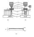
以下に本発明の一実施形態を説明する。まず、図2(a)、(b)に示す評価試験装置について説明する。この装置は、湾曲させ、ループ状にした試験片を挟みこみしごいていく挟持移動冶具21、試験片の両端部を固定する端部固定手段24、挟持移動冶具21をZ方向に移動させ、結果として試験片をしごきあげることになるZステージ22、湾曲部観察手段と試験片とを相対的に位置変化させ、湾曲部観察手段によって試験片の湾曲部全体が観察できるようにするために、試験片の幅方向にスキャンするXステージ23と、湾曲部の状態を観察し、剥離を検出する為の湾曲部観察手段としての光学顕微鏡14、そして湾曲部の曲率半径を記録し測定するためのカメラ25からなる。31は試験片、すなわち積層体である。ここで、光学顕微鏡の視野内に試験片の全体像が入るならば、Xステージ23はなくてもよい。
【0012】
次に、試験片31について説明する。本発明で評価することのできる積層体とは、可撓性を有する透明な基材に、薄膜を一層または複数層積層した積層体である。具体的には蒸着膜を形成した透明防湿フィルム等が挙げられる。
【0013】
このような積層体を短冊状に切り出し、本発明の試験片として評価する。試験片の形状は湾曲部を形成することができ、それを小さくするようしごきあげ、薄膜の剥離が生じた際の湾曲部の曲率を測定することができるならば制限はないが、本実施例で用いた試験片は、図2(c)に示すように、透明基材32上に薄膜33を形成した積層体をカッターにより幅1cm、長さ12cmの長方形に切り出したものである。この試験片31を薄膜33が内側になるよう湾曲させループ状にし、挟持移動冶具21で挟み込み、端部固定手段24で試験片の両端を固定する。試験片の薄膜について、蒸着膜だけでなく、例えばスパッタリングによる薄膜など、その他各種薄膜作成方法で作られた薄膜についても同様に評価することができる。
【0014】
【実施例】
以下に本発明の薄膜密着強度測定装置及びそれを用いた測定方法の一例を図を用いて説明する。
試験片のセットは、図2(a)(b)に示すように、試験片を湾曲させ、その両端部の重なった部分がようやく通る程度の隙間の開いた挟持移動冶具21で挟み込む。次に試験片の両端部を揃え、高さ方向(Z軸方向)に動かないよう端部固定手段24で固定する。本発明の実施例では端部の固定は粘着テープで行っているが、例えば接着剤等、不必要に試験片に負担をかけることなく固定の目的を果たせれば制限はない。
【0015】
試験片を挟みこむ挟持移動冶具21はZステージ22に固定されており、Zステージ22が上方に移動するにつれ挟持移動冶具21も移動し、試験片31をしごき、試験片のつくる湾曲部は小さくなってゆく。Zステージの移動は自動であり、本実施例における移動速度は16μm/secと設定した。この移動速度は任意の値に設定することができる。
【0016】
Xステージ23は、試験片幅方向を自動往復し、かつZステージの移動に対して十分速い速度で移動するよう、1mm/secに設定した。Zステージ22の移動速度よりも十分に早ければXステージ23の移動速度も任意である。これにより試験片湾曲部でいつ薄膜の剥離が生じたかを50倍の光学顕微鏡14でリアルタイムに観察(水平方向視野1.7mm)することが可能である。
【0017】
Zステージ22を移動させ、試験片31を湾曲部(ループ)が小さくなる方向に向かってしごいていった。本実施例では光学顕微鏡14による観察で湾曲部の薄膜剥離が発生し、その剥離長さが顕微鏡視野X軸方向の半分(0.6mm)に達した時にZ方向の移動を止めた。本実施例では剥離長さが0.6mmの時としたが、Z方向の移動を終了する判断基準は測定者が任意に設定してよい。
【0018】
曲率半径の測定は、図2(a)の方向から試験片31の湾曲部をデジタルカメラ25で撮影し、曲率半径を求める専用のアプリケーションで計算した。測定の際、図3に示すように湾曲部の円弧に対し、2mm幅内の円弧に対する曲率半径を測定値とした。曲率半径は、円弧の形状を座標データとして抽出し、円の方程式に最小二乗法によりフィッティングを行うことにより求めた。
【0019】
試験片として、厚さ100μmのPET基材上に厚さ300nmの蒸着膜を形成し、それを耐光性試験機(スガ試験機ロングライフフェードメーター U48)にいれたものを用いた。耐光性試験時間は0、24、48時間であり、実施形態で示した方法でそれぞれの剥離が発生する曲率半径を求めた。本発明による密着強度測定試験は各3回ずつ行い、その結果を図4に示した。耐光性試験時間により、PET基材と蒸着膜の密着強度は劣化することが知られており、この傾向が本発明による密着強度測定試験からも確認された。また、これらの試験片について、碁盤目テープ法により評価した結果を表1に示す。剥離したマス目の数は、マス目100個につきx個のマス目で剥離が生じたことを、「x/100」と表記している。
【0020】
【表1】

表1から、耐光性試験0時間及び24時間では薄膜(蒸着膜)の密着強度について碁盤目テープ法では差がないことがわかる。しかし本発明の薄膜密着強度測定方法によれば、耐光性試験0時間に対し、24時間の方が剥離発生曲率が大きくなっていることから(図4)薄膜の密着強度が落ちていることがわかる。また同じ条件で耐光性試験を行った試験片に対し、3回の密着強度測定を行ったが、いずれも同じ傾向を示していることが図4からわかる。このように、本測定によれば密着強度の微小な差異が再現性よく、定量的に測定できる事が示された。
【0022】
【発明の効果】
以上より、本発明の密着強度評価方法によれば、積層体の薄膜形成面を内側に湾曲させループ状にし、そのループ(湾曲部)が小さくなるようにしごき、薄膜の剥離が発生したときの曲率半径を測定するので、積層体及びその薄膜表面になにも触れさせることなく基材と薄膜との密着強度の測定をすることができ、得られた測定結果は再現性に優れている。また、密着強度の微小な差異を曲率半径の大きさとして定量的に示す事が可能となった。
【0023】
【図面の簡単な説明】
【図1】従来の4点曲げ試験の概略図である。
【図2】本発明による薄膜の密着強度測定装置の実施の一例を示す説明図である。(a)は測定装置の側面図、(b)は測定装置の正面図、(c)は試験片の断面図である。
【図3】図3は湾曲部の曲率半径を求める際の概略図である。
【図4】図4は本測定方法で蒸着膜の剥離発生曲率を求めた測定結果である。
【符号の説明】
11…歪ゲージ
12…下部支点
13…上部支点
14…光学顕微鏡
21…挟持移動冶具
22…Zステージ
23…Xステージ
24…端部固定手段
25…カメラ
31…試験片(積層体)
32…透明基材
33…薄膜
41…座標データ測定点[0001]
BACKGROUND OF THE INVENTION
The present invention relates to an evaluation method and an evaluation apparatus for a laminate having one or more thin films on a flexible transparent substrate, and particularly the thin film adhesion in a transparent film having functionality such as a vapor deposition film. The present invention relates to an intensity evaluation method and an evaluation apparatus.
[0002]
[Prior art]
Conventionally, as a test method for evaluating the adhesion strength of a thin film to a substrate, there are a cross cut method, a cross cut tape method, and an X cut tape method as specified in JIS K5400. There are also bending tests in the standards of JIS, ASTM and ISO. A proposal for quantitatively and efficiently performing such a method has been made by
[0003]
[Patent Document 1]
JP-A-5-182255 [0004]
[Problems to be solved by the invention]
Among the conventional test methods, the cross-cut method is a method in which cuts reaching the base material through the thin film on the test piece are formed in a checkered pattern, and the adhesion state of the thin film is visually observed. However, visual observation of the adhesion state around the cut is not quantitative, and it is difficult to observe even a subtle difference in adhesion.
[0005]
In the cross-cut tape method, cuts reaching the base material through the thin film on the test piece are made in a cross-cut pattern, adhesive tape is applied on the cross-cut, and the thin film and the tape are adhered by rubbing with an eraser, and the tape is peeled off. This is a method of visually observing the state of adhesion of the thin film after the aging. However, in this method, when rubbing with an eraser to obtain adhesion between the thin film and the tape, the brittle film itself breaks, and there is a possibility that the accurate adhesive force cannot be measured. In addition, since the test method includes many artificial factors, there is a drawback that the test method itself has poor reproducibility.
[0006]
The X-cut tape method penetrates the thin film on the test piece, attaches the cut on X reaching the base material with a cutter knife, attaches a cellophane adhesive tape on it, peels it off, and between the base material or the thin film This is a method for examining the superiority or inferiority of adhesion. However, this method is not quantitative as the cross cut method and cross cut tape method, and there is a risk of damaging the film when rubbed with an eraser to obtain close contact with the cellophane adhesive tape. It has the disadvantage of being.
[0007]
The bending test will be described by taking the four-point bending test shown in FIG. 1 as an example. The
[0008]
The present invention has been made in view of the above-mentioned problems, and the object of the present invention is to provide a method for evaluating the adhesion strength of a laminate without causing any contact with the surface of the thin film and with good reproducibility, and adhesion. A strength evaluation apparatus is provided.
[0009]
[Means for Solving the Problems]
The present invention has been made in order to achieve the above object, and the first invention according to
[0010]
According to a second aspect of the present invention, after a laminate having one or more thin films on a flexible transparent substrate is bent with the thin film inside, a curved portion is formed and sandwiched . A thin jig comprising: a holding jig movable so as to reduce the bending portion; a bending portion observing means for observing a state of the bending portion; and a measuring means for measuring a radius of curvature of the bending portion. It is an adhesion strength evaluation device.
[0011]
DETAILED DESCRIPTION OF THE INVENTION
An embodiment of the present invention will be described below. First, the evaluation test apparatus shown in FIGS. 2 (a) and 2 (b) will be described. This device moves the clamping and moving
[0012]
Next, the
[0013]
Such a laminate is cut into strips and evaluated as a test piece of the present invention. The shape of the test piece is not limited as long as the curved portion can be formed, and the curvature of the curved portion when the thin film is peeled off can be measured by squeezing to make it small. As shown in FIG. 2 (c), the test piece used in was obtained by cutting a laminate in which a
[0014]
【Example】
Hereinafter, an example of a thin film adhesion strength measuring apparatus and a measuring method using the same according to the present invention will be described with reference to the drawings.
As shown in FIGS. 2 (a) and 2 (b), the set of test pieces is bent with a holding and moving
[0015]
The
[0016]
The
[0017]
The
[0018]
The measurement of the radius of curvature was calculated by a dedicated application for photographing the curved portion of the
[0019]
As a test piece, a vapor deposition film having a thickness of 300 nm was formed on a PET substrate having a thickness of 100 μm, and this was put into a light resistance tester (Suga Tester Long Life Fade Meter U48). The light resistance test time was 0, 24, and 48 hours, and the radius of curvature at which each peeling occurred was obtained by the method shown in the embodiment. The adhesion strength measurement test according to the present invention was performed three times each, and the results are shown in FIG. It is known that the adhesion strength between the PET substrate and the deposited film deteriorates depending on the light resistance test time, and this tendency was also confirmed from the adhesion strength measurement test according to the present invention. In addition, Table 1 shows the results of these test pieces evaluated by the cross-cut tape method. The number of squares peeled off indicates that “x / 100” means that peeling occurred in x squares per 100 squares.
[0020]
[Table 1]
From Table 1, it can be seen that there is no difference in the cross-cut tape method for the adhesion strength of the thin film (deposited film) at 0 hours and 24 hours in the light resistance test. However, according to the thin film adhesion strength measuring method of the present invention, the peeling occurrence curvature is larger in 24 hours than in the light resistance test of 0 hours (FIG. 4). Recognize. Moreover, although the adhesive strength measurement was performed 3 times with respect to the test piece which performed the light resistance test on the same conditions, it turns out that all show the same tendency. Thus, according to this measurement, it was shown that minute differences in adhesion strength can be measured quantitatively with good reproducibility.
[0022]
【The invention's effect】
As described above, according to the adhesion strength evaluation method of the present invention, the thin film forming surface of the laminated body is bent inward to form a loop, and the loop (curved portion) is made small so that peeling of the thin film occurs. Since the radius of curvature is measured, the adhesion strength between the substrate and the thin film can be measured without touching the laminate and the surface of the thin film, and the obtained measurement results are excellent in reproducibility. In addition, it is possible to quantitatively indicate a minute difference in adhesion strength as the radius of curvature.
[0023]
[Brief description of the drawings]
FIG. 1 is a schematic view of a conventional four-point bending test.
FIG. 2 is an explanatory diagram showing an example of implementation of a thin film adhesion strength measuring apparatus according to the present invention. (A) is a side view of a measuring apparatus, (b) is a front view of a measuring apparatus, (c) is sectional drawing of a test piece.
FIG. 3 is a schematic diagram for obtaining a radius of curvature of a bending portion.
FIG. 4 is a measurement result obtained by obtaining a peeling occurrence curvature of a deposited film by this measurement method.
[Explanation of symbols]
DESCRIPTION OF SYMBOLS 11 ... Strain gauge 12 ...
32 ...
Claims (2)
Priority Applications (1)
| Application Number | Priority Date | Filing Date | Title |
|---|---|---|---|
| JP2003129844A JP4020004B2 (en) | 2003-05-08 | 2003-05-08 | Thin film adhesion strength evaluation method and adhesion strength evaluation apparatus |
Applications Claiming Priority (1)
| Application Number | Priority Date | Filing Date | Title |
|---|---|---|---|
| JP2003129844A JP4020004B2 (en) | 2003-05-08 | 2003-05-08 | Thin film adhesion strength evaluation method and adhesion strength evaluation apparatus |
Publications (2)
| Publication Number | Publication Date |
|---|---|
| JP2004333309A JP2004333309A (en) | 2004-11-25 |
| JP4020004B2 true JP4020004B2 (en) | 2007-12-12 |
Family
ID=33505530
Family Applications (1)
| Application Number | Title | Priority Date | Filing Date |
|---|---|---|---|
| JP2003129844A Expired - Fee Related JP4020004B2 (en) | 2003-05-08 | 2003-05-08 | Thin film adhesion strength evaluation method and adhesion strength evaluation apparatus |
Country Status (1)
| Country | Link |
|---|---|
| JP (1) | JP4020004B2 (en) |
Families Citing this family (1)
| Publication number | Priority date | Publication date | Assignee | Title |
|---|---|---|---|---|
| JP6888633B2 (en) * | 2016-11-25 | 2021-06-16 | Agc株式会社 | Base material evaluation method and bent glass evaluation device |
-
2003
- 2003-05-08 JP JP2003129844A patent/JP4020004B2/en not_active Expired - Fee Related
Also Published As
| Publication number | Publication date |
|---|---|
| JP2004333309A (en) | 2004-11-25 |
Similar Documents
| Publication | Publication Date | Title |
|---|---|---|
| KR101179339B1 (en) | Method of manufacturing liquid crystal display device | |
| CN114512561A (en) | Method for testing bonding strength of photovoltaic laminated sample, cell piece and adhesive film | |
| Tohmyoh et al. | Structural elasticity for tensile deformation of a single human hair and the comparison with it for the bending deformation | |
| CN110243781A (en) | The detection method of leather and fur products | |
| CN105067516A (en) | Method for testing repeated sticking force of mold releasing agent for shielding adhesive tape | |
| JP2012247305A (en) | Inter-layer peeling inspection device for plastic card and peeling inspection method using the same | |
| CN109470560A (en) | A Dynamic Characterization Method for Compression/Bending Properties of Materials Microstructure | |
| JP4878070B2 (en) | Manufacturing method of liquid crystal display element | |
| EP3502666A1 (en) | Device for measuring backscattered radiation by a sample and measuring method using such a device | |
| JP2004333309A (en) | Thin film adhesion strength evaluation method and adhesion strength evaluation device | |
| JP4305267B2 (en) | Thin film layer adhesion evaluation method | |
| JP4341431B2 (en) | Thin film adhesion strength evaluation method and apparatus | |
| JP5659665B2 (en) | Adhesion strength evaluation method | |
| CN1182381C (en) | Measuring method of ultrathin slice thickness based on atomic force microscope | |
| CN115266570A (en) | Method for detecting bonding strength of composite film on surface of PVC (polyvinyl chloride) mesh fabric material | |
| CN212008091U (en) | Clamp structure for uniaxial tension test of aorta | |
| CN115329585A (en) | Method for evaluating stripping force of release film | |
| JPH04177143A (en) | Preparation of thin slice of microscope sample | |
| CN208636116U (en) | The sub-wire device of high-strength chemistry filament tow | |
| JP5096988B2 (en) | Method for measuring the delamination state of the stratum corneum | |
| JPH10332560A (en) | Apparatus and method for evaluating thin film adhesion strength | |
| WO2014021052A1 (en) | Tape for forming double eyelid | |
| JP2008309721A (en) | Strain occurrence location detection component and strain occurrence location detection device | |
| JP2006250590A (en) | Whisker measurement sheet, measuring device using the same, and measurement method of whisker | |
| Lucia et al. | Detection of cell forces by measuring deformation of polymer films via interference reflection microscopy |
Legal Events
| Date | Code | Title | Description |
|---|---|---|---|
| A621 | Written request for application examination |
Free format text: JAPANESE INTERMEDIATE CODE: A621 Effective date: 20060320 |
|
| A977 | Report on retrieval |
Free format text: JAPANESE INTERMEDIATE CODE: A971007 Effective date: 20070525 |
|
| A131 | Notification of reasons for refusal |
Free format text: JAPANESE INTERMEDIATE CODE: A131 Effective date: 20070605 |
|
| A521 | Written amendment |
Free format text: JAPANESE INTERMEDIATE CODE: A523 Effective date: 20070727 |
|
| TRDD | Decision of grant or rejection written | ||
| A01 | Written decision to grant a patent or to grant a registration (utility model) |
Free format text: JAPANESE INTERMEDIATE CODE: A01 Effective date: 20070904 |
|
| A61 | First payment of annual fees (during grant procedure) |
Free format text: JAPANESE INTERMEDIATE CODE: A61 Effective date: 20070917 |
|
| FPAY | Renewal fee payment (event date is renewal date of database) |
Free format text: PAYMENT UNTIL: 20101005 Year of fee payment: 3 |
|
| R150 | Certificate of patent or registration of utility model |
Free format text: JAPANESE INTERMEDIATE CODE: R150 |
|
| FPAY | Renewal fee payment (event date is renewal date of database) |
Free format text: PAYMENT UNTIL: 20101005 Year of fee payment: 3 |
|
| FPAY | Renewal fee payment (event date is renewal date of database) |
Free format text: PAYMENT UNTIL: 20111005 Year of fee payment: 4 |
|
| FPAY | Renewal fee payment (event date is renewal date of database) |
Free format text: PAYMENT UNTIL: 20111005 Year of fee payment: 4 |
|
| FPAY | Renewal fee payment (event date is renewal date of database) |
Free format text: PAYMENT UNTIL: 20121005 Year of fee payment: 5 |
|
| FPAY | Renewal fee payment (event date is renewal date of database) |
Free format text: PAYMENT UNTIL: 20131005 Year of fee payment: 6 |
|
| LAPS | Cancellation because of no payment of annual fees |