JP4036743B2 - Target structure for Archery Biathlon - Google Patents
Target structure for Archery Biathlon Download PDFInfo
- Publication number
- JP4036743B2 JP4036743B2 JP2002372586A JP2002372586A JP4036743B2 JP 4036743 B2 JP4036743 B2 JP 4036743B2 JP 2002372586 A JP2002372586 A JP 2002372586A JP 2002372586 A JP2002372586 A JP 2002372586A JP 4036743 B2 JP4036743 B2 JP 4036743B2
- Authority
- JP
- Japan
- Prior art keywords
- target
- archery
- biathlon
- slide bar
- target board
- Prior art date
- Legal status (The legal status is an assumption and is not a legal conclusion. Google has not performed a legal analysis and makes no representation as to the accuracy of the status listed.)
- Expired - Fee Related
Links
- 239000007787 solid Substances 0.000 claims description 2
- 239000000463 material Substances 0.000 description 6
- 230000007797 corrosion Effects 0.000 description 3
- 238000005260 corrosion Methods 0.000 description 3
- 238000004519 manufacturing process Methods 0.000 description 3
- 229910001220 stainless steel Inorganic materials 0.000 description 3
- 239000010935 stainless steel Substances 0.000 description 3
- 230000000694 effects Effects 0.000 description 2
- 239000011347 resin Substances 0.000 description 2
- 229920005989 resin Polymers 0.000 description 2
- 239000002023 wood Substances 0.000 description 2
- 229910000831 Steel Inorganic materials 0.000 description 1
- 238000003754 machining Methods 0.000 description 1
- 238000000926 separation method Methods 0.000 description 1
- 239000010959 steel Substances 0.000 description 1
Images






Classifications
-
- F—MECHANICAL ENGINEERING; LIGHTING; HEATING; WEAPONS; BLASTING
- F41—WEAPONS
- F41J—TARGETS; TARGET RANGES; BULLET CATCHERS
- F41J7/00—Movable targets which are stationary when fired at
- F41J7/04—Movable targets which are stationary when fired at disappearing or moving when hit
-
- F—MECHANICAL ENGINEERING; LIGHTING; HEATING; WEAPONS; BLASTING
- F41—WEAPONS
- F41J—TARGETS; TARGET RANGES; BULLET CATCHERS
- F41J3/00—Targets for arrows or darts, e.g. for sporting or amusement purposes
- F41J3/0004—Archery targets
Landscapes
- Engineering & Computer Science (AREA)
- General Engineering & Computer Science (AREA)
- Aiming, Guidance, Guns With A Light Source, Armor, Camouflage, And Targets (AREA)
Description
【0001】
【発明の属する技術分野】
本発明は、アーチェリーバイアスロン用の的構造(特に、ドロップ−ダウンターゲット)に関する。
【0002】
【従来の技術】
従来の、アーチェリーの標的は、複数の藁層を備えた多層構造のマット本体と、表シート,裏シートとを綴じ糸を介して縫い締めるものがある(例えば、特許文献1参照)。
【0003】
【特許文献1】
特開平9−318297号公報
【0004】
【発明が解決しようとする課題】
雪上で行うアーチェリーバイアスロン競技に於いては、矢が的に当たると、的が後方へ転倒しなければならず、しかも、矢,的及び装置が損傷してはならない。しかし、上述した従来のアーチェリーの標的のマット本体は、矢が突き刺さるものであり、また、矢が当たると的が後方へ転倒する構造ではない。
【0005】
そこで、従来、的の前面に矢が当たり一定の力以上の力が掛かると的が後方へ転倒するように、前後に揺動する木製アームに的を取付けて、鉛直よりも僅かに前方へ傾斜して、固定枠に当たって、保つ構造のものが使用されている。しかし、風が強いときには、不意に的が後方へ倒れる欠点があり、かつ、完全に鉛直状でない等の欠点があった。
【0006】
【課題を解決するための手段】
本発明に係るアーチェリーバイアスロン用の的構造は、アーチェリーバイアスロン用的盤を固定台に鉛直起立状態及び後方転倒状態に切換自在に保持する保持手段を、備え、該保持手段は、上記的盤の裏面から水平状に後方へ延設されたスライド棒と、該スライド棒を軸心方向にスライド可能に保持する軸受と、該スライド棒を前方へ弾発付勢するスプリングと、鉛直起立状態で上端に該軸受が付設され下端側が上記固定台に前後揺動可能に枢着された揺動アームと、該揺動アームの一部に揺動自在に枢結されて上記固定台の当接部に当接して該揺動アームの揺動を阻止するストッパ片と、上記的盤に矢が当たって上記スライド棒が後方へスライドしたことを感知し上記ストッパ片を揺動して上記当接部から離脱させる感知機構とを、具備する。
【0007】
また、感知機構は、上記ストッパ片に一体状に形成されると共にカム受け用勾配部を有する感知アームと、的盤に矢が当たって外力を受けスライド棒が水平後方へ所定距離移動した際に上記勾配部に当接するように上記スライド棒側に付設されたカムピンとを、有する。さらに、複数の的盤を1台の固定台に設け、後方転倒状態の夫々の的盤を、同時に鉛直起立状態に復元させる復元手段を具備し、さらに、該復元手段は、的盤が後方転倒状態にあるとき、夫々のストッパ片及び感知アームの弯曲部に当接する当接ピンを有し上記複数の的盤を同時に鉛直起立状態に復元させる杆を備え、夫々の杆が、1本の軸に固着されるのも好ましい。
【0008】
【発明の実施の形態】
以下、実施の形態の示す図面に基づき、本発明を詳説する。
【0009】
図1,図2及び図3は、本発明のアーチェリーバイアスロン用の的構造の実施の一形態を示す側面図である。アーチェリーバイアスロンは、雪山,スキー場等で行われ、的に矢を当てて転倒させる競技である。この的は、アーチェリーバイアスロン用的盤1と、固定台22と、的盤1を固定台22に鉛直起立状態及び後方転倒状態に切換自在に保持する保持手段Kとを、備えている。
【0010】
図1に於て、このアーチェリーバイアスロン用の的構造は、アーチェリーバイアスロン用的盤1と、固定台22と、的盤1を固定台22に鉛直起立状態及び後方転倒状態に切換自在に保持する保持手段Kとを、備えている。的盤1は、円形の表て盤2と、表て盤2と一体状に貼着される木製,鋼板製,ステンレス製または樹脂製等の裏盤37と、から成る。表て盤2は、前方から当たる矢7の先端部を損傷させず、防食性を有するゴム製等とする。なお、図示の実施の形態以外に、的盤1としては、スライド棒3の先端に固着される白色ゴムキャップ部材と、この白色ゴムキャップの先端部が挿入固着される貫孔を中心に有する黒色ゴム盤(表て盤2)とをもって、構成するのも、好ましく、特に、的の表面の中心───いわゆるスポット───に白色丸印が露出して、的盤1として好適である(図示省略)。
【0011】
また、固定台22は、矢7が保持手段Kに当たらないよう保護する前ガード板19を備え、後方転倒する保持手段Kの落下の衝撃を吸収するためのゴム製等のクッション材31を付設している。なお、クッション材31を他の位置に付設するも自由であって、例えば、感知アーム24の後方下端を延長して被当接部とし、クッション材31を、図1の前ガード板19と底壁との隅部の位置に配設し、かつ、ストッパ板23の下半部を切欠状とした構造であっても良い。
【0012】
さらに、保持手段Kは、的盤1の裏盤37の裏面6から水平状に後方へ延設されたスライド棒3と、スライド棒3を軸心方向にスライド可能に保持する軸受4と、スライド棒3を前方へ弾発付勢するスプリング11と、鉛直起立状態で上端に軸受4が付設され下端側が固定台22に前後揺動可能に枢着された揺動アーム13とを有する。
【0013】
スライド棒3は、丸棒または円筒形状であり、このスライド棒3を挿嵌して保持する(図1〜図3では2個配設された)軸受4は、摩擦抵抗の小さい材質である。揺動アーム13は、上部から下部へ長手方向に延びた薄板形状の部材で、上端側には、軸受4を付設する固定具5が、ボルト・ナットやネジ等で螺着される。揺動アーム13の下端側は、固定台22の前ガード板19裏面に付設される固定板18と、枢支軸25で前後揺動可能になるように、枢着される。
【0014】
さらに、保持手段Kは、薄板形状のストッパ片14を具備する。このストッパ片14の上端側は、揺動アーム13の上下の中間附近の一部に、枢支軸15にて、揺動自在に枢結される。また、下端側は、固定台22に付設されたストッパ板23の当接部17に当接して揺動アーム13の揺動を阻止する。
【0015】
さらに、保持手段Kは、的盤1に矢が当たって外力Fを受け水平後方へ移動して、ストッパ片 14 を当接部 17 から離脱させる感知機構Rを有している。すなわち、この感知機構Rは、ストッパ片14と一体状に枢支軸25よりも上方に形成されると共にカム受け用勾配部9を有する感知アーム24と、的盤1に矢7が当たって外力Fを受けスライド棒3が水平後方へ所定距離L移動した際に勾配部9に当接するようにスライド棒3側に付設されたカムピン21とを、有する。感知アーム24の上端側30は、ストッパ片14の下端側20よりも後方になるよう形成される。
【0016】
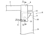
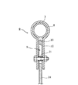
図4,図5は感知機構Rの要部拡大側面図で、図6は、図4のA−A断面図である。感知アーム24の上端側30には、カム受け用勾配部9を一部に有する開口10が形成されている。棒補助具8の上部は、スライド棒3の後部に固設され、下部は、図6のように、感知アーム24の開口10に挿嵌された短円筒状のカムピン21を両側から挟んで、カムピン21をボルト・ナットやネジで回転可能に保持する。
【0017】
ここで、保持手段Kを成すスプリング11は、図1に示すように、軸受4を把持する固定具5と、スライド棒3に付設される棒補助具8とを、連結しており、スライド棒3を前方へ弾発付勢する。また、他のスプリング12が、揺動アーム13と、感知アーム24とを、連結しており、図1の状態では、スプリング12が、感知アーム24を前方へ弾発付勢して、微小な外力が感知アーム24にかかってもストッパ片 14 を当接部 17 から離脱させない。矢7が的盤1に当たって図2の状態になると、カムピン21が勾配部9に当接するので、スプリング12は、スプリング11と共に、スライド棒3を前方へ弾発付勢する。
【0018】
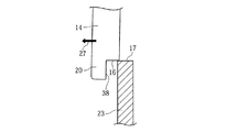
図7,図8,図9に示すように、固定台22の底壁部または前ガード19裏面に付設されたストッパ板23の上方へ向いた先端部は、当接部17に相当する。ストッパ片14の下端側20には、ストッパ板23の当接部17と当接する係止部16が形成される。図7のように、的盤1及び保持手段Kの荷重が、係止部16と当接部17の当接箇所で、係止方向26へ働き、的盤1が鉛直起立状態に保持される。図7〜図9に示す如く、下端側20に、後方切欠形状の切欠部38を形成し、この切欠部38をストッパ板23に当接させると、的盤1が、鉛直起立状態から前方へは倒れず、この状態が保持される。
【0019】
本発明のアーチェリーバイアスロン用の的構造は、上述したように雪山やスキー場等の屋外で使用されるので、防食性を有する材質とする。すなわち、スライド棒3・揺動アーム13・ストッパ片14及び感知アーム24・固定台22は、ステンレス,樹脂または木製等とし、スプリング11,12はステンレス等の防食性を有する材質とする。
【0020】
図10は、後方転倒状態の的盤1を復元させる構造の説明用側面図である。複数の的盤1…を1台の固定台22に設け、後方転倒状態の夫々の的盤1を、同時に鉛直起立状態に復元させる復元手段32を具備する。すなわち、複数の的盤1…を1台の固定台22に設けたアーチェリーバイアスロン用の的構造であって、的盤1が後方転倒状態にあるとき、ストッパ片14・感知アーム24の一体状部材に形成される弯曲部33に当接する当接ピン34を有し上記複数の的盤1…を同時に鉛直起立状態に復元させる杆35…を備え、夫々の杆35…が、1本の軸36に挿嵌され固着される。
【0021】
図2のように、二点鎖線の鉛直起立状態の的盤1に、前方から矢7が当たると、外力Fを受け、的盤1とスライド棒3が、軸受4にガイドされつつ水平移動する。このとき、棒補助具8のカムピン21が、(図4のような)感知アーム24の開口10の底部から、(図5のような)カム受け用勾配部9に摺接する後方向28へ移動して、感知アーム24が、下方向29へ下がる。
【0022】
後方向28への移動が所定距離Lを越えると、感知アーム24が、下方向29へ下がり、(図2に於て)枢支軸15を中心に、揺動し、図8のようにストッパ片14が、ストッパ板23の当接部17から離脱方向27へ移動する。そして、図9のように、ストッパ片14が、ストッパ板23の当接部17より離脱して、的盤1とスライド棒3を保持する揺動アーム13が、図3のように、枢支軸25を中心に後方へ転倒した状態となる。このとき、保持手段Kが、固定台22の底に付設されたクッション材31上に落下するので、保持手段Kの損傷を防ぐ。
【0023】
後方向28への移動が所定距離L以内であれば、スプリング11,12の弾発付勢によって、カムピン21は図4の状態へ戻り、ストッパ片 14 及び当接部 17は、図7のような状態のままであり、的盤1,スライド棒3,棒補助具8等は、図1の状態へ戻る。スプリング11,12は、的盤1の下部が約 1.1kgの外力Fを受けた際に、後方向28へ所定距離L移動できる弾発力を有する。これは、18gの矢7が、単位時間当たり約 130kmの速度で的盤1に当たるときの外力に相当する。
【0024】
感知機構Rは、上述した感知アーム24を具備する構造以外に設計変更自由であって、スライド棒3の後方と、ストッパ片14の下端側20の後方に、夫々接触可能な1本のプッシュプルワイヤを揺動アーム13に設けるのもよい。この場合は、鉛直起立状態の的盤1に、前方から矢7が当たって外力Fを受け、的盤1とスライド棒3が、後方へ所定距離L水平移動してプッシュプルワイヤの一端側を押すと、ワイヤの他端側が、ストッパ片14の下端側20を押して、ストッパ片 14 が当接部 17 から離脱し、的盤1が後方転倒状態となる。
【0025】
図10に於いて、軸36を時計廻りに回すと、当接ピン34は凹状弯曲部33に当接し滑りながらストッパ片14及び感知アーム24の一体状部材を押し上げ、的盤1,保持手段K及び復元杆35は、実線の状態から、二点鎖線の状態へとなる。1台の固定台22に複数台の的盤1…と復元杆35とを配設して、同時に複数台の的盤1…を鉛直起立状態へ復元させる。
【0026】
以上のように、本発明の的構造は、的盤1の後方の保持手段Kにより、的盤1の前面に矢7が当たって外力Fを受けた場合には確実にストッパ片 14 が当接部 17 から離脱するので、アーチェリーバイアスロン競技に適している。また、ストッパ片 14 と当接部 17 の当接・離脱によって鉛直起立状態と後方転倒状態を切換えるという簡素な構成で製造も容易でありながら、的盤1,保持手段Kの荷重による力で保持するという強固なストッパ機能を有する。そして、このストッパ機能により、的盤1は、前面から風などの圧力を受けても、鉛直起立状態に保持され倒れない。
【0027】
また、的盤1に矢7が当たると、スライド棒3が後方へ移動してスプリング11の弾発力によって衝撃を吸収するので、矢7の先端及び的盤1が損傷するのを防ぐことができる。
【0028】
感知機構Rによって、矢7が的盤1に当たる力を利用して的盤1を後方転倒状態にすることができる。すなわち、スライド棒3が後方へ所定距離L移動すると、カムピン21がカム受け用勾配部9と当接するという簡易な仕組みでありながら、この感知機構Rは、的盤1を後方転倒状態にすることができる。また、カムピン21と、カム受け用勾配部9とは、保持手段Kの一部に設けられたもので、製造も大変容易である。
【0029】
復元手段32によって、複数並設された的盤1…が、射撃後の後方転倒状態から鉛直起立状態に復元される。すなわち、軸36(に連結された図外のハンドルレバー等)を回すだけで、後方転倒した複数の的盤1…を同時に素早く鉛直起立状態にすることができるので、競技の進行がスムーズになり、その操作も容易である。そして、紐やワイヤ等により、離れた場所からでも復元することができる。弯曲部33は、保持手段Kの一部を切断加工すればよく製作も容易であり、当接ピン34を有する復元杆35と軸36の製造及び配設は容易である。
【0030】
【発明の効果】
本発明は、上述の構成により次のような著大な効果を奏する。
【0031】
(請求項1によれば、)的盤1の後方の保持手段Kにより、的盤1の前面に矢が当たって所定以上の外力を受けた場合には確実にストッパ片 14 が当接部 17 から離脱するので、アーチェリーバイアスロン競技に適している。また、ストッパ片 14 と当接部 17 の当接・離脱によって鉛直起立状態と後方転倒状態を切換えるという簡素な構成で製造も容易でありながら、的盤1,保持手段Kの荷重による力で保持するという強固なストッパ機能を有する。そして、このストッパ機能により、的盤1は、前面から風などの圧力を受けても、鉛直起立状態に保持され、不意に倒れることがない。
【0032】
また、的盤1に矢7が当たると、スライド棒3が後方へ移動してスプリング 11 の弾発力によって衝撃を吸収するので、矢7の先端及び的盤1が損傷するのを防ぐことができる。
【0033】
(請求項2によれば、)感知機構Rによって、矢7が的盤1に当たる力を利用して的盤1を確実に後方転倒状態にすることができる。すなわち、スライド棒3が後方へ所定距離L移動すると、カムピン21がカム受け用勾配部9と当接するという簡易な仕組みでありながら、この感知機構Rは、的盤1を確実に後方転倒状態にすることができる。また、カムピン21と、カム受け用勾配部9とは、保持手段Kの一部に設けられたもので、製造も容易である。
【0034】
(請求項3によれば、)復元手段32によって、複数並設された的盤1…が、射撃後の後方転倒状態から鉛直起立状態に復元される。すなわち、軸36を回すだけで、後方転倒した複数の的盤1…を同時に素早く鉛直起立状態にすることができるので、競技の進行がスムーズになり、その操作も容易である。そして、紐やワイヤ等により、離れた場所からでも復元することができる。弯曲部33は、保持手段Kの一部を機械(切断)加工すればよく製作も容易であり、当接ピン34を有する復元杆35と軸36の製造及び配設は容易である。
【図面の簡単な説明】
【図1】 本発明のアーチェリーバイアスロン用の的の実施の一形態を示す側面図である。
【図2】 矢が前方から的盤に当たり後方へ水平移動した側面図である。
【図3】 的盤が後方転倒状態となった側面図である。
【図4】 感知機構Rの要部拡大側面図である。
【図5】 スライド棒が後方へ水平移動したときの要部拡大側面図である。
【図6】 図4のA−A断面図である。
【図7】 要部拡大側面図である。
【図8】 ストッパ片が離脱方向へ移動した要部拡大側面図である。
【図9】 ストッパ片が当接部と離脱した要部拡大側面図である。
【図10】 全体の説明用側面図である。
【符号の説明】
1 的盤
3 スライド棒
4 軸受
6 裏面
7 矢
9 カム受け用勾配部
11 スプリング
13 揺動アーム
14 ストッパ片
17 当接部
21 カムピン
22 固定台
24 感知アーム
32 復元手段
33 弯曲部
34 当接ピン
35 復元杆
36 軸
F 外力
K 保持手段
L 所定距離
R 感知機構 [0001]
BACKGROUND OF THE INVENTION
The present invention relates to a target structure for archery biathlon (particularly a drop-down target).
[0002]
[Prior art]
As a conventional archery target, there is one in which a mat body having a multilayer structure including a plurality of heel layers, a front sheet, and a back sheet are sewn together with a binding thread (see, for example, Patent Document 1).
[0003]
[Patent Document 1]
JP-A-9-318297 [0004]
[Problems to be solved by the invention]
In archery biathlon competitions on snow, when an arrow hits, the target must fall backwards and the arrow, target and equipment must not be damaged. However, the conventional archery target mat body described above has an arrow that pierces, and does not have a structure in which the target falls backward when the arrow hits.
[0005]
Therefore, conventionally, a target is attached to a wooden arm that swings back and forth so that when the arrow hits the front of the target and a force of a certain level or more is applied, the target tilts backward, and tilts slightly forward from the vertical. And the thing of the structure which hits a fixed frame and keeps is used. However, when the wind is strong, there is a drawback that the target unexpectedly falls backward, and there is a disadvantage that it is not completely vertical.
[0006]
[Means for Solving the Problems]
Structure for archery biathlon according to the present invention, the holding means for holding freely switching archery biathlon for specific panel in the vertical upright state and a backward fall state to the solid Jodai, comprising, said retaining means, the manner A slide bar horizontally extending rearward from the back surface of the board, a bearing for holding the slide bar so as to be slidable in the axial direction, a spring for elastically biasing the slide bar forward, and a vertically standing state The swinging arm is provided with the bearing at the upper end and the lower end is pivotally attached to the fixed base so as to be swingable back and forth, and the swinging arm is pivotally connected to a part of the swinging arm to contact the fixed base. A stopper piece that abuts against the arm and prevents the swinging arm from swinging, and detects that the arrow hits the target board and the slide bar slides backward, and swings the stopper piece to contact the And a sensing mechanism for separating from the part .
[0007]
In addition, the sensing mechanism is formed integrally with the stopper piece and has a sensing arm having a cam receiving gradient portion, and when the arrow hits the target board and receives an external force to move the slide bar to the horizontal rear by a predetermined distance. And a cam pin attached to the slide rod side so as to abut against the slope portion. Furthermore, a plurality of target boards are provided on one fixed base, and provided with restoration means for restoring each of the target boards in a backward-turned state to a vertical standing state at the same time. Each having a contact pin that contacts the bent portion of each stopper piece and the sensing arm, and the plurality of target boards are simultaneously restored to a vertically upright state, each of which has one shaft It is also preferable that it is fixed to.
[0008]
DETAILED DESCRIPTION OF THE INVENTION
Hereinafter, the present invention will be described in detail based on the drawings shown in the embodiments.
[0009]
1, 2 and 3 are side views showing an embodiment of the target structure for the archery biathlon of the present invention. Archery Biathlon is a competition that takes place at snowy mountains, ski resorts, etc., and hits an arrow and falls. This target includes an archery
[0010]
In FIG. 1, the target structure for the archery biathlon is the archery
[0011]
The
[0012]
Furthermore, the holding means K includes a
[0013]
The
[0014]
Furthermore, the holding means K includes a thin plate-
[0015]
Further, the holding means K has a sensing mechanism R that causes the
[0016]
4 and 5 are enlarged side views of the main part of the sensing mechanism R, and FIG. 6 is a cross-sectional view taken along the line AA of FIG. On the
[0017]
Here, as shown in FIG. 1, the
[0018]
As shown in FIGS. 7, 8, and 9 , the front end portion of the
[0019]
Since the target structure for the archery biathlon of the present invention is used outdoors such as a snowy mountain or a ski resort as described above, it is made of a material having corrosion resistance. That is, the
[0020]
FIG. 10 is a side view for explaining the structure for restoring the
[0021]
As shown in FIG. 2, when an arrow 7 hits the
[0022]
When the movement in the
[0023]
If the movement in the
[0024]
The sensing mechanism R can be freely changed in design other than the structure provided with the
[0025]
In FIG. 10, when the
[0026]
As described above, the target structure of the present invention ensures that the
[0027]
Further, when the arrow 7 hits the
[0028]
By the sensing mechanism R, the
[0029]
The restoring means 32 restores the plurality of
[0030]
【The invention's effect】
The present invention has the following remarkable effects by the above-described configuration.
[0031]
(According to claim 1) When the holding means K behind the
[0032]
Further, when the arrow 7 hits the
[0033]
(According to
[0034]
(According to claim 3 ) The restoration means 32 restores the plurality of
[Brief description of the drawings]
FIG. 1 is a side view showing an embodiment of a target for the archery biathlon of the present invention.
FIG. 2 is a side view in which an arrow hits the target board from the front and horizontally moves backward.
FIG. 3 is a side view of the target board in a state of falling backward.
4 is an enlarged side view of a main part of a sensing mechanism R. FIG.
FIG. 5 is an enlarged side view of a main part when the slide bar is horizontally moved rearward.
6 is a cross-sectional view taken along the line AA in FIG.
FIG. 7 is an enlarged side view.
FIG. 8 is an enlarged side view of a main part in which a stopper piece has moved in a disengagement direction.
FIG. 9 is an enlarged side view of a main part where a stopper piece is separated from a contact part.
FIG. 10 is an overall explanatory side view.
[Explanation of symbols]
1
11 Spring
13 Swing arm
14 Stopper piece
17 Contact part
21 Cam pin
22 Fixed base
24 Sensing arm
32 How to restore
33 Folding Club
34 Contact pin
35 Restoration
36 Axis F External force K Holding means L Predetermined distance R Sensing mechanism
Claims (3)
該保持手段(K)は、上記的盤(1)の裏面(6)から水平状に後方へ延設されたスライド棒(3)と、該スライド棒(3)を軸心方向にスライド可能に保持する軸受(4)と、該スライド棒(3)を前方へ弾発付勢するスプリング( 11 )と、鉛直起立状態で上端に該軸受(4)が付設され下端側が上記固定台( 22 )に前後揺動可能に枢着された揺動アーム( 13 )と、該揺動アーム( 13 )の一部に揺動自在に枢結されて上記固定台( 22 )の当接部( 17 )に当接して該揺動アーム( 13 )の揺動を阻止するストッパ片( 14 )と、上記的盤(1)に矢(7)が当たって上記スライド棒(3)が後方へスライドしたことを感知し上記ストッパ片( 14 )を揺動して上記当接部( 17 )から離脱させる感知機構(R)とを、具備することを特徴とするアーチェリーバイアスロン用の的構造。Archery biathlon for specific panel (1) a solid Jodai (22) in a vertical upright position and holding means for switching freely held in a backward fall state (K), comprising,
The holding means (K) includes a slide bar (3) horizontally extending rearward from the back surface (6) of the target board (1), and the slide bar (3) is slidable in the axial direction. A bearing (4) to be held, a spring ( 11 ) for elastically urging the slide bar (3) forward , and the bearing (4) is attached to the upper end in a vertically standing state, and the lower end side is the fixed base ( 22 ). the front and rear swingably pivotally mounted swing arm (13), abutment swing arm swingably pivotally connected to a part of (13) with the fixed base (22) (17) A stopper piece ( 14 ) that abuts against the swinging arm ( 13 ) and prevents the swinging arm ( 13 ) from swinging, and that the arrow (7) hits the target board (1) and the slide bar (3) slides backward. And a sensing mechanism (R) that swings the stopper piece ( 14 ) to disengage it from the contact portion ( 17 ). Target structure for Archery Biathlon.
Priority Applications (1)
| Application Number | Priority Date | Filing Date | Title |
|---|---|---|---|
| JP2002372586A JP4036743B2 (en) | 2002-12-24 | 2002-12-24 | Target structure for Archery Biathlon |
Applications Claiming Priority (1)
| Application Number | Priority Date | Filing Date | Title |
|---|---|---|---|
| JP2002372586A JP4036743B2 (en) | 2002-12-24 | 2002-12-24 | Target structure for Archery Biathlon |
Publications (2)
| Publication Number | Publication Date |
|---|---|
| JP2004205079A JP2004205079A (en) | 2004-07-22 |
| JP4036743B2 true JP4036743B2 (en) | 2008-01-23 |
Family
ID=32811154
Family Applications (1)
| Application Number | Title | Priority Date | Filing Date |
|---|---|---|---|
| JP2002372586A Expired - Fee Related JP4036743B2 (en) | 2002-12-24 | 2002-12-24 | Target structure for Archery Biathlon |
Country Status (1)
| Country | Link |
|---|---|
| JP (1) | JP4036743B2 (en) |
-
2002
- 2002-12-24 JP JP2002372586A patent/JP4036743B2/en not_active Expired - Fee Related
Also Published As
| Publication number | Publication date |
|---|---|
| JP2004205079A (en) | 2004-07-22 |
Similar Documents
| Publication | Publication Date | Title |
|---|---|---|
| US5263721A (en) | End of game feature for a pop target game | |
| US5263722A (en) | Automatically resettable target | |
| US4657261A (en) | Spring mounted silhouette archery target apparatus | |
| CA2637889C (en) | Card shoe with force resist mechanism | |
| CN111686436A (en) | Fast replacing structure of ice skate blade | |
| JP4036743B2 (en) | Target structure for Archery Biathlon | |
| US6513815B2 (en) | In-line racing skate propulsion device | |
| US6983938B2 (en) | Rapid fire resetting target | |
| US6485034B1 (en) | Roller assembly of in-line roller skate | |
| US2816536A (en) | Ring projecting toy | |
| US10814195B2 (en) | Stomp and catch game | |
| US20080280739A1 (en) | Inversion exerciser | |
| JP2640774B2 (en) | Self-releasing ski coupling unit | |
| CN218900782U (en) | Bowling shooting game machine | |
| CN111186515B (en) | A kind of children's scooter buffer device and using method thereof | |
| JPS58130070A (en) | Safety binding | |
| WO2003092829A1 (en) | Snowboard and snowboard brake | |
| JP2009279129A5 (en) | ||
| WO1997016226A1 (en) | Specific binding for a snowboard or the like | |
| FR2776531A1 (en) | Bowling game plate with base plate, track and return ducts | |
| EP1522334B1 (en) | Shoe binding for a sports board | |
| US11498640B1 (en) | Brake pedal lever tip peg for motorcycle | |
| WO2007003014A1 (en) | Traction device for a snow ski | |
| CN208296690U (en) | A kind of remote reset gunnery training target holder | |
| JP3042854U (en) | Bullet firing toys |
Legal Events
| Date | Code | Title | Description |
|---|---|---|---|
| A621 | Written request for application examination |
Free format text: JAPANESE INTERMEDIATE CODE: A621 Effective date: 20050905 |
|
| A977 | Report on retrieval |
Free format text: JAPANESE INTERMEDIATE CODE: A971007 Effective date: 20070720 |
|
| A131 | Notification of reasons for refusal |
Free format text: JAPANESE INTERMEDIATE CODE: A131 Effective date: 20070724 |
|
| A521 | Written amendment |
Free format text: JAPANESE INTERMEDIATE CODE: A523 Effective date: 20070907 |
|
| TRDD | Decision of grant or rejection written | ||
| A01 | Written decision to grant a patent or to grant a registration (utility model) |
Free format text: JAPANESE INTERMEDIATE CODE: A01 Effective date: 20071009 |
|
| A61 | First payment of annual fees (during grant procedure) |
Free format text: JAPANESE INTERMEDIATE CODE: A61 Effective date: 20071030 |
|
| R150 | Certificate of patent or registration of utility model |
Free format text: JAPANESE INTERMEDIATE CODE: R150 |
|
| FPAY | Renewal fee payment (event date is renewal date of database) |
Free format text: PAYMENT UNTIL: 20101109 Year of fee payment: 3 |
|
| FPAY | Renewal fee payment (event date is renewal date of database) |
Free format text: PAYMENT UNTIL: 20111109 Year of fee payment: 4 |
|
| FPAY | Renewal fee payment (event date is renewal date of database) |
Free format text: PAYMENT UNTIL: 20111109 Year of fee payment: 4 |
|
| FPAY | Renewal fee payment (event date is renewal date of database) |
Free format text: PAYMENT UNTIL: 20121109 Year of fee payment: 5 |
|
| LAPS | Cancellation because of no payment of annual fees |